EP0681439B1 - Meuble de travail - Google Patents
Meuble de travail Download PDFInfo
- Publication number
- EP0681439B1 EP0681439B1 EP94906163A EP94906163A EP0681439B1 EP 0681439 B1 EP0681439 B1 EP 0681439B1 EP 94906163 A EP94906163 A EP 94906163A EP 94906163 A EP94906163 A EP 94906163A EP 0681439 B1 EP0681439 B1 EP 0681439B1
- Authority
- EP
- European Patent Office
- Prior art keywords
- table according
- working table
- vertical
- table top
- working
- Prior art date
- Legal status (The legal status is an assumption and is not a legal conclusion. Google has not performed a legal analysis and makes no representation as to the accuracy of the status listed.)
- Expired - Lifetime
Links
- 230000000903 blocking effect Effects 0.000 claims description 6
- 230000000295 complement effect Effects 0.000 claims description 6
- XAGFODPZIPBFFR-UHFFFAOYSA-N aluminium Chemical compound [Al] XAGFODPZIPBFFR-UHFFFAOYSA-N 0.000 claims description 5
- 229910052782 aluminium Inorganic materials 0.000 claims description 5
- 238000007789 sealing Methods 0.000 claims description 5
- 229910000831 Steel Inorganic materials 0.000 claims description 4
- 239000010959 steel Substances 0.000 claims description 4
- 239000004033 plastic Substances 0.000 claims description 2
- 238000009423 ventilation Methods 0.000 claims description 2
- 239000004411 aluminium Substances 0.000 claims 1
- 238000005266 casting Methods 0.000 claims 1
- 238000004512 die casting Methods 0.000 claims 1
- 238000010276 construction Methods 0.000 abstract description 6
- 230000003014 reinforcing effect Effects 0.000 abstract 1
- 238000013461 design Methods 0.000 description 16
- 238000012360 testing method Methods 0.000 description 6
- 238000012549 training Methods 0.000 description 5
- 238000003780 insertion Methods 0.000 description 4
- 230000037431 insertion Effects 0.000 description 4
- 238000009434 installation Methods 0.000 description 4
- 239000000463 material Substances 0.000 description 4
- 238000005259 measurement Methods 0.000 description 4
- 230000000694 effects Effects 0.000 description 3
- 238000004519 manufacturing process Methods 0.000 description 3
- 238000005192 partition Methods 0.000 description 3
- 230000000712 assembly Effects 0.000 description 2
- 238000000429 assembly Methods 0.000 description 2
- 238000011161 development Methods 0.000 description 2
- 238000012423 maintenance Methods 0.000 description 2
- 238000003860 storage Methods 0.000 description 2
- 241000699670 Mus sp. Species 0.000 description 1
- 230000006978 adaptation Effects 0.000 description 1
- 239000000853 adhesive Substances 0.000 description 1
- 230000001070 adhesive effect Effects 0.000 description 1
- 230000033228 biological regulation Effects 0.000 description 1
- 230000005540 biological transmission Effects 0.000 description 1
- 230000015572 biosynthetic process Effects 0.000 description 1
- 238000006243 chemical reaction Methods 0.000 description 1
- 230000008030 elimination Effects 0.000 description 1
- 238000003379 elimination reaction Methods 0.000 description 1
- 238000005516 engineering process Methods 0.000 description 1
- 238000011156 evaluation Methods 0.000 description 1
- 238000001125 extrusion Methods 0.000 description 1
- 230000002349 favourable effect Effects 0.000 description 1
- 210000003128 head Anatomy 0.000 description 1
- 238000007689 inspection Methods 0.000 description 1
- 230000007257 malfunction Effects 0.000 description 1
- 238000012544 monitoring process Methods 0.000 description 1
- 210000001331 nose Anatomy 0.000 description 1
- 238000003825 pressing Methods 0.000 description 1
- 238000012545 processing Methods 0.000 description 1
- 230000008707 rearrangement Effects 0.000 description 1
- 230000000284 resting effect Effects 0.000 description 1
- 230000006641 stabilisation Effects 0.000 description 1
- 238000011105 stabilization Methods 0.000 description 1
- 230000004936 stimulating effect Effects 0.000 description 1
- 238000010998 test method Methods 0.000 description 1
Images




Classifications
-
- A—HUMAN NECESSITIES
- A47—FURNITURE; DOMESTIC ARTICLES OR APPLIANCES; COFFEE MILLS; SPICE MILLS; SUCTION CLEANERS IN GENERAL
- A47B—TABLES; DESKS; OFFICE FURNITURE; CABINETS; DRAWERS; GENERAL DETAILS OF FURNITURE
- A47B21/00—Tables or desks for office equipment, e.g. typewriters, keyboards
- A47B21/06—Tables or desks for office equipment, e.g. typewriters, keyboards characterised by means for holding, fastening or concealing cables
-
- A—HUMAN NECESSITIES
- A47—FURNITURE; DOMESTIC ARTICLES OR APPLIANCES; COFFEE MILLS; SPICE MILLS; SUCTION CLEANERS IN GENERAL
- A47B—TABLES; DESKS; OFFICE FURNITURE; CABINETS; DRAWERS; GENERAL DETAILS OF FURNITURE
- A47B13/00—Details of tables or desks
- A47B13/02—Underframes
-
- A—HUMAN NECESSITIES
- A47—FURNITURE; DOMESTIC ARTICLES OR APPLIANCES; COFFEE MILLS; SPICE MILLS; SUCTION CLEANERS IN GENERAL
- A47B—TABLES; DESKS; OFFICE FURNITURE; CABINETS; DRAWERS; GENERAL DETAILS OF FURNITURE
- A47B17/00—Writing-tables
- A47B17/03—Writing-tables with substantially horizontally extensible or adjustable parts other than drawers, e.g. leaves
- A47B17/033—Writing-tables with substantially horizontally extensible or adjustable parts other than drawers, e.g. leaves with parts added to the original furniture to enlarge its surface
-
- A—HUMAN NECESSITIES
- A47—FURNITURE; DOMESTIC ARTICLES OR APPLIANCES; COFFEE MILLS; SPICE MILLS; SUCTION CLEANERS IN GENERAL
- A47B—TABLES; DESKS; OFFICE FURNITURE; CABINETS; DRAWERS; GENERAL DETAILS OF FURNITURE
- A47B87/00—Sectional furniture, i.e. combinations of complete furniture units, e.g. assemblies of furniture units of the same kind such as linkable cabinets, tables, racks or shelf units
- A47B87/002—Combination of tables; Linking or assembling means therefor
-
- A—HUMAN NECESSITIES
- A47—FURNITURE; DOMESTIC ARTICLES OR APPLIANCES; COFFEE MILLS; SPICE MILLS; SUCTION CLEANERS IN GENERAL
- A47B—TABLES; DESKS; OFFICE FURNITURE; CABINETS; DRAWERS; GENERAL DETAILS OF FURNITURE
- A47B9/00—Tables with tops of variable height
-
- A—HUMAN NECESSITIES
- A47—FURNITURE; DOMESTIC ARTICLES OR APPLIANCES; COFFEE MILLS; SPICE MILLS; SUCTION CLEANERS IN GENERAL
- A47B—TABLES; DESKS; OFFICE FURNITURE; CABINETS; DRAWERS; GENERAL DETAILS OF FURNITURE
- A47B91/00—Feet for furniture in general
-
- A—HUMAN NECESSITIES
- A47—FURNITURE; DOMESTIC ARTICLES OR APPLIANCES; COFFEE MILLS; SPICE MILLS; SUCTION CLEANERS IN GENERAL
- A47B—TABLES; DESKS; OFFICE FURNITURE; CABINETS; DRAWERS; GENERAL DETAILS OF FURNITURE
- A47B21/00—Tables or desks for office equipment, e.g. typewriters, keyboards
- A47B21/06—Tables or desks for office equipment, e.g. typewriters, keyboards characterised by means for holding, fastening or concealing cables
- A47B2021/064—Tables or desks for office equipment, e.g. typewriters, keyboards characterised by means for holding, fastening or concealing cables with power rail running along the back of the desk top and projecting upwards
-
- A—HUMAN NECESSITIES
- A47—FURNITURE; DOMESTIC ARTICLES OR APPLIANCES; COFFEE MILLS; SPICE MILLS; SUCTION CLEANERS IN GENERAL
- A47B—TABLES; DESKS; OFFICE FURNITURE; CABINETS; DRAWERS; GENERAL DETAILS OF FURNITURE
- A47B37/00—Tables adapted for other particular purposes
- A47B2037/005—Tables specially adapted for laboratories
-
- A—HUMAN NECESSITIES
- A47—FURNITURE; DOMESTIC ARTICLES OR APPLIANCES; COFFEE MILLS; SPICE MILLS; SUCTION CLEANERS IN GENERAL
- A47B—TABLES; DESKS; OFFICE FURNITURE; CABINETS; DRAWERS; GENERAL DETAILS OF FURNITURE
- A47B2200/00—General construction of tables or desks
- A47B2200/0001—Tops
- A47B2200/0003—Triangular or trapezoidal desk surface to join desks
-
- A—HUMAN NECESSITIES
- A47—FURNITURE; DOMESTIC ARTICLES OR APPLIANCES; COFFEE MILLS; SPICE MILLS; SUCTION CLEANERS IN GENERAL
- A47B—TABLES; DESKS; OFFICE FURNITURE; CABINETS; DRAWERS; GENERAL DETAILS OF FURNITURE
- A47B2200/00—General construction of tables or desks
- A47B2200/0011—Underframes
- A47B2200/002—Legs
- A47B2200/0026—Desks with C-shaped leg
-
- A—HUMAN NECESSITIES
- A47—FURNITURE; DOMESTIC ARTICLES OR APPLIANCES; COFFEE MILLS; SPICE MILLS; SUCTION CLEANERS IN GENERAL
- A47B—TABLES; DESKS; OFFICE FURNITURE; CABINETS; DRAWERS; GENERAL DETAILS OF FURNITURE
- A47B2200/00—General construction of tables or desks
- A47B2200/0011—Underframes
- A47B2200/002—Legs
- A47B2200/0027—Desks with I-shaped leg
-
- A—HUMAN NECESSITIES
- A47—FURNITURE; DOMESTIC ARTICLES OR APPLIANCES; COFFEE MILLS; SPICE MILLS; SUCTION CLEANERS IN GENERAL
- A47B—TABLES; DESKS; OFFICE FURNITURE; CABINETS; DRAWERS; GENERAL DETAILS OF FURNITURE
- A47B2200/00—General construction of tables or desks
- A47B2200/0035—Tables or desks with features relating to adjustability or folding
- A47B2200/004—Top adjustment
- A47B2200/0046—Desks with double worktop of which one at least is separately height adjustable
-
- A—HUMAN NECESSITIES
- A47—FURNITURE; DOMESTIC ARTICLES OR APPLIANCES; COFFEE MILLS; SPICE MILLS; SUCTION CLEANERS IN GENERAL
- A47B—TABLES; DESKS; OFFICE FURNITURE; CABINETS; DRAWERS; GENERAL DETAILS OF FURNITURE
- A47B2200/00—General construction of tables or desks
- A47B2200/0035—Tables or desks with features relating to adjustability or folding
- A47B2200/005—Leg adjustment
- A47B2200/0065—Bellows for desk legs
-
- A—HUMAN NECESSITIES
- A47—FURNITURE; DOMESTIC ARTICLES OR APPLIANCES; COFFEE MILLS; SPICE MILLS; SUCTION CLEANERS IN GENERAL
- A47B—TABLES; DESKS; OFFICE FURNITURE; CABINETS; DRAWERS; GENERAL DETAILS OF FURNITURE
- A47B2200/00—General construction of tables or desks
- A47B2200/0066—Workstations
- A47B2200/0073—Desk with integrated computer
Definitions
- the invention relates to work furniture according to the preamble of claim 1.
- a work table with a base frame and a height-adjustable table top is known from EP 0 107 162 A1.
- the base frame is provided with a horizontal stiffening element underneath the table top.
- a multifunction rail runs parallel to the stiffening element, which is particularly suitable for attaching visible and organizational walls, Lighting heads and other additional devices and for connection to other work tables is formed and can serve as a cable duct.
- a support leg for an office work table is known, which at the same time is intended to serve as a stand for further pieces of office furniture.
- a cheek for an office work table
- two edge profiles are screwed to a web wall connecting them and the space is covered with an inner and an outer insert wall.
- a table top is carried by the parallel cheeks.
- An office table known from DE 86 12 889.2 U1 has a cross member between two height-adjustable support feet.
- a cable duct is arranged below a table top and height-adjustable with the table top.
- the invention has for its object to provide a modular work furniture, which is put together both as an elegant office and conference table and as a stable and visually appealing computer, laboratory and technician workstation and retrofitted at any time in a particularly simple manner or can be retrofitted, which can also be optimally used and appropriately set up in terms of height and depth according to the technical and ergonomic workplace requirements and can be adapted subsequently and with particularly little effort to changed requirements.
- a room ergonomically designed piece of work furniture which has a table top resting in the area of its side edges on support arms, support feet with vertical profiles arranged below the support arms with T-slots and interior spaces for receiving a height adjustment device for the table top as well as horizontal foot brackets and cable ducts in the area of the vertical profiles and has a horizontal cable duct as a stiffening connection between the vertical profiles, double column feet are provided as support feet, each of which has the front vertical profile and a spaced and identically designed rear vertical profile.
- the height adjustment device is provided in particular in the front vertical profiles for the front table top.
- the horizontal cable duct is designed as a common cross member for the paired front vertical profiles and rear vertical profiles and fastened in the external grooves of the vertical profiles.
- at least one further working level in particular a rear table top, is attached to the rear vertical profiles fixable, which is arranged or designed taking into account an ergonomic handle line.
- the cross member provided in the rear area of the table top serves as a stiffening connection, which is connected to the vertical profiles and can be used as a horizontal cable duct or cable space.
- Aluminum extrusion profiles are preferably provided as vertical profiles, which enable a connection to other components of the modular system.
- the vertical profiles have an almost rectangular cross section with chamfered or rounded corner areas and, in addition to T-slots in both side faces, a T-slot in the end faces, the side faces of the vertical profiles on the work furniture according to the invention parallel to the side edges of the table top or run in alignment with them.
- a centrally arranged interior is complementary to a vertically adjustable inner tube and has, for example, a rectangular cross section.
- the inner tube is connected to an associated support arm of the table top and is vertically adjustable via a sliding guide for height adjustment of the at least one front table top.
- sliding surfaces or sliding elements in particular made of plastic, can be arranged on the inner tube.
- the sliding surfaces or sliding elements advantageously act as tolerance compensation at the same time.
- Permagleit lake or vertical elements can also be used for sliding guidance, which protrude into the interior, for example in a T-shape, in such a way that the inner tube is slidably guided on the crossbar.
- half-shell-like sliding elements are provided on circular cavities in the vertical profile.
- the circular cavities are formed in particular in the area of the end faces of the vertical profile and delimit the central interior.
- the height of the at least one table top can be adjusted continuously and can range from 680 to 810 mm. However, this height adjustment can also be set up at a distance, for example in a grid dimension of 30 mm or in fixed heights, for example at a height of 720, 750 or 780 mm, and can be operated manually, for example with a crank or with the aid of a motor and with one in the lower region the column feet or the vertical profiles arranged spindle or a cylinder-piston unit.
- the hand or motor control is expediently arranged on the front of the table and is easily accessible.
- the height adjustment device of the work table comprises a display device
- an ergonomically favorable table height can be set and controlled in a particularly efficient manner.
- a display device for the table height to be set is particularly recommended if several employees have to work at one workplace.
- the display device can be arranged in the area of the vertical profiles or in the area of the operating elements for the height adjustment.
- the cable duct cross member which connects two parallel support feet arranged on both sides of the table top, is fastened in the upper area of the vertical profiles of the support feet, preferably with fastening elements which are held in the T-slots of the vertical profiles.
- the work furniture is provided with double support feet, which for stabilization are equipped with a common, e.g. trough-shaped cross members are connected.
- the crossbeam which can also be used as a horizontal cable duct, connects the vertical profiles, which are arranged in pairs and spaced one behind the other, across the entire table width with the double support foot arranged on the opposite side to form an extremely robust substructure.
- the cable duct is in particular stepped trough-shaped and runs in a preferred construction below the rear longitudinal edge of the table top.
- the table top is arranged as a first, front working level of the work station and can not only be adjustable in height, but also, if necessary, also adjustable in inclination and / or displaceable and extractable.
- An inclination adjustment can be implemented, for example, with the aid of a pivot axis that interacts with the support arms in a connection area of the inner tube.
- Horizontal adjustability can be achieved via slide rails in the area of the support arms.
- the table top as the first working level, can be pulled out to the front via a sliding plate guide and, if appropriate, also removed.
- the sliding plate guide can be designed, for example, as a split bar with a sliding plate guide arranged in the front table area and with a sliding plate guide arranged in the rear table area.
- Sliding plate guides are inserted with pins from below into holes in the table top and partially screwed.
- the front sliding plate guide has blocking elements, for example blocking springs, to limit and pull it out safely. These protrude downwards and come into contact with a certain extension dimension when the table top is pulled out or in engagement with a corresponding counter element or a contact surface in the area of the support arms. Since the slide guides are provided with longitudinal openings, it is possible to press in or raise the locking springs from below, so that the table top can be pulled further forward or fully.
- a cover is expediently provided for the horizontal, trough-shaped cable duct support, which cover can be designed to be removable or pivotable.
- a horizontal gap over almost the entire cover for the entry and exit of cables and lines is equipped with a sealing cable duct, for example with double sealing lips or brush strips, so that an orderly line routing from and to the devices of a work station is guaranteed.
- An intermediate space in the area of a double support foot between the two vertical profiles arranged and spaced one behind the other, which is covered with a specially designed veneer to improve the overall optical-aesthetic impression, is expediently used as an additional vertical cable duct.
- a panel is provided in the upper area that provides a removable surface or predetermined breaking points Breakthrough and for cable routing from the vertical to the horizontal cable duct.
- An advantage is the possibility to use the vertical profiles, in particular the rear vertical profiles of the double support feet, to enlarge the work surface and the workplace optionally in addition to the front, first work level, with a second, backwards working level and / or with a table structure as a third to equip the higher level.
- a piece of work furniture with a height and / or inclination-adjustable second level can be used in particular for CAD workstations in which the second level can be used to accommodate monitors and can be adjusted according to the individual wishes with regard to height and inclination.
- a cross member running between the first and second levels is particularly advantageous to use as a cable duct for devices and devices arranged on both levels.
- a horizontal cable duct arranged as a stiffening connection or cross member between vertical profiles, in particular spaced apart in table width can be formed from a plurality of longitudinal profiles which are detachably connected to one another on their longitudinal edges to form an approximately triangular cross section.
- the basic profile is for this purpose provided a fastening area, which can be designed, for example, as a cavity for receiving an adapter-like connecting element.
- the connecting element can be fastened in the T-slots of the vertical profile and with the aid of a clamping part in the cavity of the basic profile in order to hold the cable duct securely.
- the base profile is expediently connected as a corner profile and via snap-fit connections at the end to an approximately arch-shaped cover or to a rear profile or an intermediate profile which serves to widen the cable duct.
- the longitudinal profiles which are made in particular of aluminum, are designed as hollow profiles which have T-slots and / or screw channels for the optional fastening of accessories, for example sockets, cable holders, etc.
- caps can be attached to cover the vertical cable ducts, which are formed in the space between double support feet or in a veneered rear area of a support foot.
- the caps are provided with locking elements and can be clipped on.
- a support structure-like element is expedient, which is provided with recesses and noses for holding top and side surfaces.
- the rear vertical profiles of the double support feet can be provided with self-centering extension profiles in particular.
- the extension profile is almost identical to the vertical profile of the column or double column feet.
- a third working level directly adjoining a rear area of the front table top it makes sense to provide an extension profile that is open to the inside.
- cables can be routed from the vertically arranged profiles into the horizontal cable ducts or supports or directly to the devices in a particularly efficient manner.
- an elastic, detachable cover of the longitudinal profile opening of the extension profile is recommended.
- so-called soft lips or brush strip arrangements can be provided for the elastic covering and cable routing.
- a cross strut which serves as a positioning level or as a storage shelf for receiving different assemblies, components and / or devices, can be attached to upwardly elongated vertical profiles.
- an upper receiving plane as a horizontal, upper cable duct which, for example, has a housing base with holding or guiding elements that can be swung open downwards.
- it can also be designed to be tilt-adjustable, the usual devices having to be attached to or in the vertical profiles of the third level.
- a table top extending to the rear vertical profiles which is provided as the first, front working plane, is expediently provided in the area of the rear vertical profiles with complementary recesses to the cross section of the vertical profiles.
- these recesses are expediently covered with a removable, for example with a snap-in or insertable plate-shaped insert.
- the respective upper, open end faces of the vertical profiles are provided with a plate-shaped cover cap adapted to the outline of the vertical profiles, which e.g. can be pressed into the circular interior of the vertical profiles with pegs.
- a housing area for accommodating devices is provided in the workplace from space-economical and ergonomic aspects, which is provided almost outside a viewing and gripping area, so that in particular the table top as the first, front working level is principally kept free of devices.
- the workplace space concept according to the invention provides a fourth level, which is arranged essentially in the lower area below the table top and accommodates basic supply devices such as PCs, plug-in cards as well as power supply devices, transformers and the like.
- a rear table top can be provided as a second level, while a connection field lies in the ergonomic grip area and accommodates, for example, devices such as, in particular, measuring and display devices.
- a particularly effective use of space results if the display unit, in particular a monitor, is fastened, for example pivotably, to an extension profile of the third level outside the front worktop.
- a fourth-level housing design enables effective and effective HF shielding of the various devices, which can additionally be protected against one another by an HF shielding arrangement. This reduces the probability of errors and power loss at test stations.
- An installation of, in particular, starable fan assemblies is provided in order to prevent heat build-up while minimizing noise pollution.
- a uniform service and maintenance concept can be implemented, which results in a reduction in maintenance costs. By operating the devices uniformly, especially with an appropriate program, errors are reduced and shorter training times are made possible.
- An integrated wiring or wiring is expediently provided, which also includes bus systems and enables computers to be networked without problems. This improves the transmission options for measurement data, their acquisition, evaluation and processing. Another advantage is better production monitoring.
- the integrated cabling means less susceptibility to malfunction of the entire device complex or the workplace and a more rational inspection. Unintentional loosening of cables or wiring is almost impossible.
- a major effect of the integrated arrangement of personal computers, basic supply devices, etc. is less space, an extremely stimulating overall impression of a workplace and material savings as a result of the elimination of individual housings.
- the work furniture comprises at least one table base cabinet to be arranged below the table top, in particular a mobile container, which can extend up to close to the table top and in a suitable adaptation to a stepped trough-shaped cable duct support and / or to a device area forming a fourth level approximately complementary deck area is provided.
- This design enables a base cabinet or a roll container to be optimally positioned in a particularly simple manner, and it can also be fixed, for example with the aid of a Velcro fastener on the rear cable duct carrier.
- the base cabinet or roll container can be designed to accommodate various attachments, for example to accommodate open trays for in particular office material or for basket-like and / or mat-equipped attachments, depending on the workplace requirements.
- the mobile container has a correspondingly lower height.
- so-called active edges are provided in the area of the front longitudinal edge of the table top, which are designed to accommodate additional storage options, for example insert trays.
- the work furniture according to the invention can be arranged in a particularly simple and visually appealing configuration to form a corner combination.
- a corner table top is attached with its support arms to the inner tube of the associated vertical profile if the corner table top is to be adjustable in height together with the table tops adjoining on the side. Otherwise, a fastening in the longitudinal grooves of the vertical profiles can be provided.
- Support feet or double support feet which are provided with detachable and / or exchangeable foot brackets and which can advantageously be disassembled and reassembled in the use position of the work furniture or the work table, have proven to be particularly advantageous.
- An expedient constructive design of a base element, which connects a vertical profile with a horizontal foot bracket, and an end connection area of the foot bracket ensure a self-centering and a self-locking receptacle and an uncomplicated fastening.
- a change of a foot arm can be carried out without interference during a test procedure or during a measurement and the like.
- a particularly simple construction and an extremely simple assembly and disassembly of a foot bracket is ensured if a vertical profile of a column foot assigned to the table top is connected to a horizontally arranged foot bracket which can be removed and replaced in the use position of the work furniture.
- a base element designed to be complementary to the vertical profile is arranged below the vertical profile and is detachably connected to the vertical profile, for example by means of screw connections, and has a front insertion opening and an easily accessible connection area, it is possible to insert a foot extension, which has a connecting block, horizontally into the base element and fasten.
- a particularly advantageous releasable fastening is achieved at the connection area of the base element or at the connection block of the foot arm via an inclined screw connection.
- plinth connectors can be arranged, which connect two vertical profiles of a double support foot at a distance. If necessary, a shorter foot extension can be inserted into the rear base element.
- a U or double U profile which is open at the bottom, in particular an aluminum, die cast or sheet steel deep-drawn part, is advantageous.
- a base part which is open at the bottom is expediently used as the base element.
- the foot boom and Base element construction allows a particularly simple assembly and any replacement of a foot bracket on site without time-consuming rearrangement work.
- the insertion opening of the base elements can expediently be closed with the aid of cover elements if no foot extension is provided.
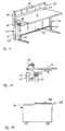
- Figures 1a to 1f show examples of different variants of a piece of work furniture according to the invention, which is constructed in a modular manner and can be equipped with different components according to the intended use.
- work furniture 1 according to the invention has a table top 6 as a front, first work plane, which is in the area of its Lateral edges rests on wedge-shaped support arms 8 and can be adjusted in height and / or inclination and / or can be extended forwards, for example 20 cm.
- the extendibility can be achieved via sliding and guide elements between the underside of the table top 6 and the support arms 8.
- the table top 6 is supported via support feet 2 connected to the support arms 8, etc. via double supports - feet 12, which are provided with at least one horizontal foot bracket 30, a base element 20 and vertical profiles 10, 11.
- the foot arm 30 is wedge-shaped in analogy to the support arm 8, which is of almost the same length, and provides a functionally and optically successful overall impression with T-grooves 18 formed in the longitudinal direction on the vertical profiles 10 (see FIG. 2).
- FIG. 1a shows a technician's work station with a double support foot 12 and a cross member 5 which is arranged as a load-bearing element and cross bracing and at the same time can be used as a horizontal cable duct and has a stepped trough-shaped design.
- the cross member 5 is fastened with lateral end faces (not shown) in the T-grooves 18 (FIG. 2) of the side faces of the front vertical profiles 10 and the identically designed, rear vertical profiles 11.
- the double support foot 12 has a rear base element 20 in addition to the front one Base element 21, which forms a unit with a base connector 22 and, together with the cable duct cross member 5, forms a stable substructure for the work furniture, in the exemplary embodiment for a technical workplace.
- the elements for height adjustment of the table top 6 are covered between the front vertical profiles 10 and the support arms 8 with a flexible sealing element, for example with a rubber bellows 9 or a rubber sleeve, in a form-fitting and detachable manner.
- Fig. 1b shows e.g. a CAD work station, which also has a double support foot 12 and a trough-shaped cable duct cross member 5.
- a front table top 6 is connected to the front vertical profile 10 in an adjustable manner, while a second, rear table top 7 is supported on a rear vertical profile 11 by means of a visible inner tube 14 and a pivot axis 29.
- a horizontal cable duct cross member 5 serves to supply the devices present on both table tops 6, 7.
- the depth of the second table top 7 is adapted to a rear foot bracket 31, which, like a front foot bracket 30, is detachably fastened in an associated base element 20 or 21, the vertical profiles 10 and 11 being connected to these base elements 20 and 21, respectively.
- FIG. 1c shows a further technician's work station, which essentially corresponds to the technician's work station according to FIG. 1a, but only has a first working level in the form of a particularly deep table top 6 which extends beyond the rear vertical profiles 11.
- FIG. 1d shows an office and technician workstation with a table top 6 which is height-adjustable in steps, the height adjustment of which is described in connection with FIGS. 2 to 5.
- Fig. 1e office work table shown which is provided with a support foot 2 with a front foot extension 30 and a short, rear foot extension 31, the vertical profile 11, the associated base element 21 and the base connector have been removed and the rear foot extension fixed.
- the table top 6 is adjustable in height, while a conference table according to FIG. 1f has a table top 6 which rests rigidly on a support arm 8 and is supported on support feet 2.
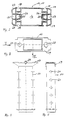
- Fig. 2 shows in a horizontal section the formation of the vertical profiles 10, 11 of the column feet 2 and the double column feet 12.
- the vertical profiles 10, 11 have an almost rectangular cross section, with beveled corner areas 23 between parallel and / or aligned to the side edges of the Table tops 6, 7 extending side surfaces are each provided with two T-grooves 18 and shorter end surfaces each with a T-groove 19.
- the corner areas 23 can also be rounded.
- an inner tube 14 in a central, almost rectangular inner space 16
- an inner tube 14 can be adjusted in height via a spindle (not shown).
- Two spindles can also be provided, for example in the circular interior 25 of the vertical profile 10, 11.
- the inner tube 14 is a steel tube and is complementary to the interior 16 of the aluminum extruded profile 10, 11.
- the steel inner tube 14 is adjusted vertically and in stages by means of a sliding guide, a grid dimension being predetermined by the spacing of bores 24 along the inner tube 14 and being 30 mm, for example.
- the inner tube 14 has an upper, enlarged connection area 17 which is provided with a circular bore 27 and an oval bore 28 which is for connection to at least one, serve for example with a crank or with a motor-operated spindle in an interior of the vertical profile 10, 11.
- a pivot axis 29 for an inclinable table top 7 can also be formed in the connecting area 17.
- adjoining the interior 16 half-shell-shaped sliding elements 26 are arranged, which can have separate sliding linings. Alternatively, sliding or permagliding surfaces can also be glued onto the inner tube 14.
- FIG. 6 shows a corner office combination as a further exemplary embodiment of work furniture which can be adapted to the requirements of the workplace and the spatial situation.
- the same reference numerals are again used for identical features.
- the height of two table tops 6, which are connected and supported by support arms 8 with double support feet 12, can be adjusted.
- To form a third working level 33, which at the left worktable 6 is a functional partition 34 with a filing plane 35 and horizontal grooves 36 for fastening various devices, for example lamps, panels and the like (not shown), on the rear vertical profiles 11
- Double support feet 12 self-centering extension profiles 37 are attached, the upper end faces of which are covered with a cover cap 38.
- a corresponding recess 32 is formed in the table top 6, which can optionally be covered with a plate-shaped insert (not shown).
- a cable duct cross member 5 which is connected to a vertical cable duct 13 formed by a cover between the front vertical profile 10 and the rear vertical profile 11.
- FIG. 6 illustrates the optically and aesthetically successful design of an office work table with an additional construction level 33.
- An additional level 33 is also mounted on the right table top 6 via a schematically illustrated adapter 39, which is preferably fastened in the rear area of the support arms 8.
- a corner plate 4 is fastened to the inner tubes of the adjacent vertical profiles 10 via holding elements (not shown).
- the insertion openings of the base elements 20 are covered with a cover element 15, which can contain a leveling screw.
- a table base cabinet 41 is arranged under the table top 6 of the left work table, the height of which is adapted to the cable duct cross member 5 at least in a rear area.
- Figure 7 shows a technician workstation with a table top 6 as the front, first working level, a rear table top 7 as a second working level and with a relatively high table structure as a third level 33, which serves as an adjustable level 40 (see Fig. 8) for built-in devices 42 is formed.
- the height-adjustable table top 6 is provided with two active edges 57 that can be plugged close to the side edges 43 for the easily accessible reception of various work tools.
- the extensions 37 which are plugged onto the rear vertical profiles 11, extend beyond the pivoted devices 42 and are provided with a cover cap 38. It is advantageous to design the upper, inclinable adjustment plane 40 as an upper, horizontal cable duct 58 (see Fig. 18), which ensures invisible and protected cable routing to the devices of the third level.
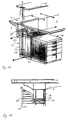
- Figure 9 shows in an improved ergonomic room concept a piece of work furniture with base cabinet units 44, which are arranged in the region of the double support feet 12 and attached to the vertical profiles 10, 11 and which serve to accommodate the essential supply facilities, so that on the table top 6 and a relatively low , attached to correspondingly short extension profiles 37 of the rear vertical profiles 11, third level 33, only additional and in particular display devices can be arranged.
- a panel attached in the region of a vertical cable duct 13 is provided with an upper triangular panel 45 (FIG. 10), which has fastening elements for detachable connection to the paneling of the vertical cable duct 13 and with plug elements for mounting in an end-face T-groove 19 of the vertical profile 11 is provided.
- a plate-shaped cover element is attached obliquely to the triangular screen 45, with a connection between the vertical cable channels 13 and the horizontal cable channel cross member 5 with the aid of an opening in the triangular screen which is to be formed via predetermined breaking points or a removable surface 45 can be produced.
- FIG. 10 shows a section of a rear area of a table top 6 in a side view, to which a hood-like arrangement 51 for in particular small office parts is clamped.
- This arrangement 51 is also slidable along the table edge of the table top 6.
- Pivoting lamps and other table attachments and devices can be fastened in an adjustable or pivotable manner by means of displaceable table clamps of an analog design.
- a roller container 53 shown schematically in FIG. 11 has a stepped cover area 52 which is adapted to the stepped trough-shaped design of the cable carrier cross member 5 and enables quick and easy positioning below a table top 6 by a stop.
- FIG. 12 shows a schematic perspective illustration of an electronics workstation as a further developed piece of work furniture 1, which corresponds to an optimized ergonomic room concept. Identical reference signs have been used for the same features.
- Characteristic of the new room concept is a principally device-free table top 6, so that space is available for a test specimen 65 on a particularly large work surface.
- a device-free table top 6 is made possible by using the space below the table top 6 for a housing area 60 as a fourth working level.
- a housing area 60 in particular devices of the basic supply, such as controllable direct voltage devices, signal generators, etc., personal computers 64 and other modular devices and flexibly manageable plug-in cards 66 are accommodated.
- An IP-tight and / or an HF-shielded housing area 60 can have an advantageous effect on tests and tests that are as free of faults and errors as possible.
- a connection field 61 between extension profiles 37 of double support feet 12 is arranged along an ergonomic grip line 67 (see FIG. 13) as a third working level.
- operating devices 68 in the connection field 61 devices 63 of the basic supplies and voluminous devices 64 in the housing area 60 below the worktop 6, as well as display units, such as monitors 62 and operating units such as keyboards and mice (not shown) outside the worktop 6, are ergonomic Handle area 69 (see Fig. 13) arranged.
- connection field 61 is covered for an advantageous design with front plates 59 and inclined according to the ergonomic handle line 69.
- FIG. 13 shows the new ergonomic room concept with handle area 69 and housing area 60 as well as individual features of a designer design.
- a worktop 6 is infinitely adjustable between a height of at least 680 mm and a maximum of 810 mm.
- a height adjustment device which has been described by way of example in connection with FIGS. 2 to 5, is arranged in the region of a front vertical profile 10 and sealed by a rubber bellows 9.
- a cable duct 13 is provided with an arcuate cable duct cap 88.
- the connection field 61 as a third working level is arranged between extension profiles 37 of the rear vertical profiles 11.
- the foot bracket 30 and support arms 8 are curved.
- FIG. 14 A view of an office furniture 1 with a front table top 6 as a first working level, with a rear table top 7 as a second working level and with an operating level 40 as a third working level and with a base cabinet 41 is shown in FIG. 14.
- a vertical cable duct 13 runs between two Vertical profiles 10, 11 and is provided with a cable duct cap 88 and with a specially designed front panel 89.
- Figure 14 illustrates a wiring and wiring (arrows), which are integrated in the workplace and in particular are permanently installed. This results in a particularly simple and at the same time safe handling and a limitation of the possible sources of error.
- a height display device 79 is arranged in the region of a cover cap 38 for a vertical profile 10.
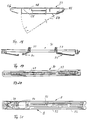
- FIG. 16 shows a piece of work furniture 1 with a height-adjustable and extendable table top 6 in a partially sectioned side view, which has a vertical cable duct 13 above a rear foot bracket 31 and a horizontal cable duct cross member 5 as a stiffening connection between vertical profiles 10.
- Foot brackets 30, 31, like the support arms 8 and the upper end regions of the vertical cable ducts 13, are curved or curved.
- the cable duct cross member 5 consists of hollow profiles connected in the circumferential direction via snap-fit connections (see FIG. 22) and is held on the vertical profile 10 via an adapter-like connecting element 74 (see FIGS. 23 to 25).
- the vertical profile 10 is detachably connected to a front foot bracket 30 and to a rear foot bracket 31 via a base element 20.
- a particularly efficient assembly and disassembly of the foot extensions 30, 31 is advantageous, which can be released and removed from the base element 20 in the horizontal direction and without changing the position of the work furniture 1.
- the foot bracket 30, for example, is inserted with an end connection block 80 into an opening 82 of the base element 20 via an end insertion opening 83 and is releasably attached to the base element 20 by means of an easily accessible connection area 84 with an oblique screw fastening.
- the rear foot bracket 31 can also be fixed to the connection area 84 of the base element 20.
- a connecting block 80 of the foot brackets 30, 31 enables self-centering and self-locking fixing on the base element 20.
- FIG. 17 shows a snap-in cable duct cap 88 which has guide slots 87 and can be fixed on a cable duct 13 according to FIG. 16 rotated by 180 °.
- a curved shape is clear, which corresponds to the design concept of the furniture variant and continues in the form of a cover 77 of the horizontal cable duct cross member 5 (see FIG. 22).
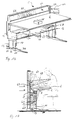
- FIG. 18 shows a schematic vertical section through a third level 33, which is designed like a housing and as an upper, horizontal cable duct 58 with a housing base 54 that can be swung open downwards.
- Guide elements 55 within the cable channel 58 ensure a protected mounting of the cables and lines.
- the front and rear longitudinal edges 56 of the cable duct 58 are rounded and wedge-shaped, analogous to the longitudinal edges of the table tops 6, 7.
- FIGS. 19, 20, 21 show a sliding plate guide 90 designed as a split bar for a front area of a horizontally displaceable table top 6.
- a rear sliding plate guide is designed analogously except for blocking elements 91.
- the sliding plate guide 90 is fastened to the lower table top 6 (not shown) via pins 97.
- Downwardly projecting sliding springs are formed as blocking elements 91, which slide in longitudinal grooves 92 of the support arms 8 during the pulling out of a table top and engage in latching openings 92 at a specific, predeterminable extension dimension. After pressing in the blocking elements, the table top 6 can be pulled out further.
- a rear support arm region 95 can be covered with a cap (not shown) which is arranged so that it can be moved so that a vertical cable duct running underneath is accessible.
- FIG. 22 shows an advantageous construction of a horizontal cable duct cross member 5 in cross section.
- the cable duct cross member 5 consists of a plurality of hollow profiles 70, 79 which are detachably connected to one another in the circumferential direction, the receiving space 81 being able to be enlarged in accordance with the requirements by an insertable, further longitudinal profile (not shown).
- an almost rectangular basic profile 70 is provided as hollow longitudinal profiles, on which an arc-shaped cover 77 is pivotably mounted.
- the cover 77 In the closed state, the cover 77 extends to form a column-shaped cable bushing 73 as far as a second, hollow profile 79 on the rear side, which is detachably connected to the basic profile 70 via an almost centrally arranged clip or snap-fit connection 76.
- a third hollow profile (not shown) in order to enlarge the cable duct.
- the base profile 70 has an almost square cavity 72 as a fastening area for receiving an adapter-like connecting element 74, which is shown schematically in FIGS. 23 to 25.
- the connecting element 74 according to FIGS. 23 to 25 is inserted with a clamping part 75 into the cavity 72 of the basic profile 70 and clamped with a wedge-shaped element (not shown) which can be fixed on the clamping part 75.
- a fixation to an adjacent vertical profile 10, 11 is achieved via a fastening flange 78 which bears against the vertical profiles 10, 11 and can be fixed via fastening openings 87 aligned with the T-slots 18 of the vertical profiles 10, 11. This ensures a secure mounting and stiffening effect of the horizontal cable duct cross member 5 on an office or workstation furniture.
Landscapes
- Tables And Desks Characterized By Structural Shape (AREA)
- Workshop Equipment, Work Benches, Supports, Or Storage Means (AREA)
- Glass Compositions (AREA)
- Lubricants (AREA)
- Securing Of Glass Panes Or The Like (AREA)
- Details Of Indoor Wiring (AREA)
Claims (32)
- Meuble de travail pour postes de travail de bureau et de technicien, avec un plateau de table (6) placé sur des bras porteurs (8) au niveau des bords latéraux (43), avec des pieds porteurs (2) qui sont reliés aux bras porteurs (8) et présentent un profilé vertical (10) avec des rainures extérieures en T (18, 19) et avec des vides intérieurs (16, 25) destinés à recevoir un dispositif de réglage en hauteur (14, 17) pour le plateau de table (6) ainsi que des embases de pied (30, 31), avec des goulottes pour câbles au niveau des profilés verticaux (10) et avec une goulotte pour câbles horizontale (5) au niveau du plateau de table (6), lequel est placé en guise de jonction de rigidité entre les profilés verticaux (10), caractérisé en ce que , pour les pieds porteurs (2), des pieds porteurs doubles (12) sont prévus, qui présentent chacun le profilé vertical avant (10) et un profilé vertical arrière (11) conformé à l'identique et placé à distance, le dispositif de réglage en hauteur (14, 17) pour le plateau de table (6) étant prévu dans les profilés verticaux avant (10), et en ce que la goulotte pour câbles horizontale (5) est conformée en support transversal commun pour les profilés verticaux avant (10) et les profilés verticaux arrière (11) disposés par paires et est fixé dans les rainures extérieures (18, 19) des profilés verticaux (10, 11), et en ce qu 'un autre plan de travail peut être fixé sur les profilés verticaux arrière (11).
- Meuble de travail selon la Revendication 1, caractérisé en ce que , pour l'autre plan de travail sur les profilés verticaux arrière (11), il est prévu un plateau de table arrière (7) qui est disposé réglable en hauteur et/ou en inclinaison et/ou est mobile horizontalement comme le plateau de table avant (6).
- Meuble de travail selon la Revendication 1 ou 2, caractérisé en ce que le dispositif de réglage en hauteur (14, 17) est conformé de manière télescopique et est réalisé sous la forme d'un tube intérieur (14) qui est placé dans un vide intérieur central (16) des profilés verticaux (10, 11).
- Meuble de travail selon la Revendication 3, caractérisé en ce que le tube intérieur (14), qui est placé avec encliquetage par paliers, à des hauteurs fixes, ou réglable verticalement en continu dans l'espace intérieur (16) des profilés verticaux (10, 11), est muni de surfaces de glissement qui sont constituées en particulier en matière synthétique.
- Meuble de travail selon la Revendication 1, caractérisé en ce que le dispositif de réglage en hauteur (14, 17) pour le plateau de table (6) comprend un dispositif d'affichage (60) qui indique en particulier des hauteurs fixes.
- Meuble de travail selon la Revendication 3, caractérisé en ce que , pour un guidage coulissant du tube intérieur (14) dans l'espace intérieur (16) des profilés verticaux (10, 11), des éléments de coulissement (26) sont prévus.
- Meuble de travail selon la Revendication 1, caractérisé en ce que le plateau de table (6) est réglable en hauteur avec un dispositif de commande placé au niveau du côté avant de la table et avec un moteur ou par action manuelle.
- Meuble de travail selon la Revendication 3, caractérisé en ce que le tube intérieur (14) est relié à au moins une broche passant dans un espace intérieur (25) des profilés verticaux (10, 11) ou à une unité à piston et cylindre.
- Meuble de travail selon la Revendication 1, caractérisé en ce que le support transversal-goulotte pour câbles horizontale (5) est conformé à la manière d'un bac et refermable et est fixé dans une partie supérieure des profilés verticaux (10, 11).
- Meuble de travail selon la Revendication 3, caractérisé en ce que le support transversal-goulotte pour câble horizontale (5) présente une fermeture pivotant en une ou plusieurs parties avec guidage de câble étanche.
- Meuble de travail selon la Revendication 10, caractérisé en ce que le support transversal-goulotte pour câble horizontale (5) est formé de plusieurs profilés longitudinaux (70, 79) qui sont reliés de manière amovible les uns aux autres sur leurs bords longitudinaux, et en ce que dans au moins un profilé longitudinal (70), il est prévu une zone de fixation (72) pour la fixation sur les profilés verticaux (10, 11).
- Meuble de travail selon la Revendication 11, caractérisé en ce que , comme profilé longitudinal, il est prévu un profilé de base creux coudé (70) qui présente comme zone de fixation (72) un vide, et en ce qu 'une fermeture incurvée (77) est placée pivotante sur le profilé de base (70).
- Meuble de travail selon la Revendication 12, caractérisé en ce que le profilé de base (70) est relié au profilé longitudinal arrière (79) par l'intermédiaire d'un assemblage à enclenchement (76) placé au milieu, en ce que , par l'intermédiaire de l'assemblage à enclenchement (76), un autre profilé creux est placé de manière encliquetable pour augmenter l'espace intérieur (81) pour les câbles et en ce que les profilés longitudinaux (70, 79) sont munis de barres et de rainures en T pour l'agencement ordonné des câbles.
- Meuble de travail selon la Revendication 1 ou 2, caractérisé en ce que le plateau de table (6) formant le premier plan de travail est agencé encliquetable et mobile horizontalement par l'intermédiaire d'un guide de plateau coulissant (90) qui est muni d'éléments de blocage (91) et est guidé dans une rainure longitudinale (92) d'un bras porteur (8).
- Meuble de travail selon la Revendication 2, caractérisé en ce qu 'à chaque fois un axe de pivotement (29) est conformé dans l'une des zones de jonction (17) du tube intérieur (14) co-opérant avec le bras porteur associé (8) des plateaux de table (6, 7).
- Meuble de travail selon la Revendication 1, caractérisé en ce qu 'un troisième plan (33) est conformé à l'aide de profilés de rallonge (37) enfichables et en particulier à centrage automatique, des profilés verticaux arrière (11), et avec une contre-fiche transversale (40) placée entre les profilés de rallonge (37) et fixée à ceux-ci.
- Meuble de travail selon la Revendication 16, caractérisé en ce qu 'un plan de rangement (40) fixé en tant que troisième plan (33) pour des appareils (42) est conformé réglable en inclinaison et/ou est conformé à la manière d'un boîtier en tant que goulotte pour câbles supérieure horizontale (58) et est muni d'éléments de guidage de câble (55) et d'un fond de boîtier (54) mobile, en particulier rabattable.
- Meuble de travail selon la Revendication 1, caractérisé en ce que , comme troisième plan de travail, une zone de raccordement (61) est placée dans une zone arrière du plateau de table (6) dans la zone de saisie ergonomique d'une ligne de saisie (67) et en ce que des appareils d'affichage, en particulier des moniteurs (62), sont disposés en particulier pivotants à l'extérieur du plateau de table (6) et de la zone de raccordement (61) sur un profilé de rallonge (37).
- Meuble de travail selon la Revendication 1, caractérisé en ce qu 'une zone de boîtier (60) est placée en tant que quatrième plan de travail sous le plateau de table (6) afin de recevoir des appareils volumineux, par exemple des unités de calcul (64), ou des cartes perforées (66), ou des modules d'appareils, et en ce qu 'un câblage intégré est prévu pour les appareils placés dans cette zone de boîtier (60).
- Meuble de travail selon la Revendication 19, caractérisé en ce que la zone de boîtier (60) est étanche IP et/ou étanche HF et en ce que des agencements d'aérateurs sont prévus en particulier pour aérer automatiquement la zone de boîtier (60).
- Meuble de travail selon la Revendication 1, caractérisé en ce que les profilés verticaux (10, 11) présentent une section pratiquement rectangulaire à coins (23) arrondis ou biseautés, et en ce que l'intérieur (16) et le tube intérieur (14) ont une section rectangulaire, pour l'essentiel complémentaire.
- Meuble de travail selon la Revendication 9, caractérisé en ce que le support transversal-goulotte pour câbles (5) est muni d'une fermeture (77) retirable ou soulevable en une ou plusieurs parties, qui présente une fente horizontale pour introduire et faire sortir les câbles avec un passage de câble étanche.
- Meuble de travail selon la Revendication 1, caractérisé en ce qu 'une goulotte pour câbles verticale (13) est conformée entre le profilé vertical avant (10) et le profilé vertical arrière (11) à l'aide d'un revêtement, qui présente dans la zone supérieure un capuchon encliquetable (88) de goulotte pour câbles et une couverture latérale (89), et en ce que la goulotte pour câbles verticale (13) est reliée pour le câblage au support transversal-goulotte pour câbles horizontale (5).
- Meuble de travail selon la Revendication 1, caractérisé en ce que des unités formant placard de dessous (44) sont placées sous le plateau de table (6) et fixées au niveau des doubles pieds supports (12).
- Meuble de travail selon la Revendication 1, caractérisé en ce que des sous-placards de table (41), en particulier des caissons roulants (53), sont placés avec une zone de couverture (52) étagée adaptée au support transversal-goulotte pour câbles horizontale (5) et en ce qu 'une zone de couverture avant est conformée pour recevoir des garnitures.
- Meuble de travail selon la Revendication 1, caractérisé en ce qu 'au moins les profilés verticaux (10) associés au plateau de table (6) sont reliés à des embases de pied (30) disposées horizontalement, qui peuvent être retirées et/ou échangées dans la position de service du meuble de travail.
- Meuble de travail selon la Revendication 26, caractérisé en ce qu 'une combinaison d'angle avec au moins deux meubles de travail (1) présente des doubles pieds supports (12), qui sont prévus au niveau d'une plaque d'angle (4) sans ou avec embases de pied extractibles (30, 31).
- Meuble de travail selon la Revendication 26, caractérisé en ce que , pour la jonction du profilé vertical (10) et de l'embase de pied (30), un élément socle (20) est prévu, qui est conformé pour le logement et la fixation amovible horizontale de l'embase de pied (30).
- Meuble de travail selon la Revendication 28, caractérisé en ce que l'élément de socle (20) présente un évidement (82) dans lequel l'embase de pied (30) est introduite avec un bloc de jonction (80) et est immobilisée avec centrage automatique et blocage automatique.
- Meuble de travail selon la Revendication 29, caractérisé en ce que le bloc de jonction (80) est placé dans une zone d'extrémité à l'intérieur de l'embase de pied (30) et en ce que l'élément de socle (20) présente une zone de jonction facilement accessible (84) qui est conformée pour recevoir un élément de fixation en prise sur le bloc de jonction (80) pour une fixation par vis oblique.
- Meuble de travail selon la Revendication 28, caractérisé en ce que l'élément de socle (20) est relié fixement à l'aide d'un connecteur de socle (22) à un deuxième élément de socle (21) ou en tant qu'unité, et en ce que les éléments de socle (20, 21) sont agencés en symétrie spéculaire l'un par rapport à l'autre.
- Meuble de travail selon la Revendication 31, caractérisé en ce que les éléments de socle (20, 21) sont conformés en pièces moulées et les embases de pied (30, 31) en pièces d'aluminium moulées par injection pratiquement en forme de U ou en pièces en acier embouti.
Applications Claiming Priority (5)
| Application Number | Priority Date | Filing Date | Title |
|---|---|---|---|
| DE9301249U DE9301249U1 (de) | 1993-01-29 | 1993-01-29 | Stützenfuß für Arbeitstische |
| DE9301249U | 1993-01-29 | ||
| DE9301248U | 1993-01-29 | ||
| DE9301248U DE9301248U1 (de) | 1993-01-29 | 1993-01-29 | Arbeitsmöbel |
| PCT/EP1994/000238 WO1994016597A1 (fr) | 1993-01-29 | 1994-01-28 | Meuble de travail |
Publications (2)
| Publication Number | Publication Date |
|---|---|
| EP0681439A1 EP0681439A1 (fr) | 1995-11-15 |
| EP0681439B1 true EP0681439B1 (fr) | 1997-04-23 |
Family
ID=25960436
Family Applications (1)
| Application Number | Title | Priority Date | Filing Date |
|---|---|---|---|
| EP94906163A Expired - Lifetime EP0681439B1 (fr) | 1993-01-29 | 1994-01-28 | Meuble de travail |
Country Status (8)
| Country | Link |
|---|---|
| US (1) | US5752449A (fr) |
| EP (1) | EP0681439B1 (fr) |
| JP (1) | JP2761103B2 (fr) |
| CN (1) | CN1123308C (fr) |
| AT (1) | ATE151966T1 (fr) |
| DE (1) | DE59402526D1 (fr) |
| ES (1) | ES2104346T3 (fr) |
| WO (1) | WO1994016597A1 (fr) |
Cited By (8)
| Publication number | Priority date | Publication date | Assignee | Title |
|---|---|---|---|---|
| DE19801496C1 (de) * | 1998-01-16 | 1999-05-06 | Knuerr Mechanik Ag | Arbeitsmöbel |
| DE19801490A1 (de) * | 1998-01-16 | 1999-07-22 | Knuerr Mechanik Ag | Anordnung zum Verschieben einer Tischplatte |
| DE19803674A1 (de) * | 1998-01-30 | 1999-08-05 | Knuerr Mechanik Ag | Arbeitsplatzsystem |
| DE19848398C1 (de) * | 1998-10-21 | 1999-10-14 | Lampertz Fab Org | Variables Arbeitsplatz-Möbelsystem mit einem aus Säulen und Fußauslegern zusammensetzbarem Möbelgestell |
| DE19805731C2 (de) * | 1998-02-12 | 2001-06-21 | Knuerr Mechanik Ag | Arbeitsplatzanordnung |
| DE20017804U1 (de) * | 2000-10-17 | 2002-02-28 | Grahl GmbH, 31595 Steyerberg | Tischbein |
| EP1862091A1 (fr) | 2006-06-02 | 2007-12-05 | Knürr AG | Mobilier à usage professionnel |
| EP2851625A1 (fr) * | 2013-09-24 | 2015-03-25 | H. Lüdi + Co. AG | Agencement de ventilation d'une pièce, en particulier un laboratoire |
Families Citing this family (67)
| Publication number | Priority date | Publication date | Assignee | Title |
|---|---|---|---|---|
| US5715761A (en) * | 1995-08-01 | 1998-02-10 | Knoll, Inc. | Article of furniture including a leg having wire management capabilities |
| BE1010044A5 (nl) * | 1996-02-15 | 1997-12-02 | Inter Company Computer Enginee | Intramodulair vrijstaand meubel. |
| DE19610347C1 (de) * | 1996-03-18 | 1997-04-03 | Lampertz Fab Org | Kabelkanalsystem für Büroeinrichtungen, insbesondere für EDV-Arbeitsplätze o. dgl. |
| DE19621547A1 (de) | 1996-05-29 | 1997-12-04 | Schaerer Soehne Ag Usm U | Modulares Inneneinrichtungssystem |
| DE29611613U1 (de) * | 1996-07-03 | 1996-09-05 | Knürr-Mechanik für die Elektronik AG, 81829 München | Arbeitstisch |
| NZ329574A (en) * | 1998-01-13 | 2000-06-23 | Formway Furniture Ltd | A height adjustable roller modesty screen for a table |
| US6082840A (en) * | 1998-04-15 | 2000-07-04 | Steelcase Development Inc. | Freestanding furniture system |
| AU6515299A (en) * | 1998-10-13 | 2000-05-01 | Herman Miller, Inc. | Work space management and furniture system |
| US6269753B1 (en) * | 1998-10-26 | 2001-08-07 | Allison C. Roddan | Cantilevered, adjustable, portable computer desk |
| AU1737100A (en) * | 1998-11-20 | 2000-06-13 | Edwin P. Lochridge | Multiple computer operator support system |
| TW366745U (en) * | 1999-01-22 | 1999-08-11 | Wen-Shan Ke | Computer desk structure with lifting function |
| US6895868B1 (en) | 1999-03-03 | 2005-05-24 | Steelcase Development Corporation | Table with two-way cover for utility access |
| US6327983B1 (en) | 1999-03-03 | 2001-12-11 | Steelcase Development Corporation | Conference table with central utility system |
| US5988076A (en) * | 1999-03-05 | 1999-11-23 | Nova-Link Limited | Combined cable manager and table connector |
| US6098822A (en) * | 1999-05-04 | 2000-08-08 | Decade Industries, Inc. | Shelving system |
| US6415723B1 (en) | 1999-05-28 | 2002-07-09 | Krueger International, Inc. | Training table with wire management |
| DE29909492U1 (de) | 1999-05-31 | 1999-08-12 | Knürr-Mechanik für die Elektronik AG, 81829 München | Arbeitsmöbel |
| USD436760S1 (en) | 1999-07-08 | 2001-01-30 | Rocky Lee Dow | Ergonomic notebook stand |
| US6199807B1 (en) * | 1999-10-01 | 2001-03-13 | Hilary Z. Ilijas | Support stand |
| US6283043B1 (en) * | 2000-01-31 | 2001-09-04 | Steelcase Development Corporation | Trader desk |
| US6647900B1 (en) | 2000-10-06 | 2003-11-18 | Krueger International, Inc. | Folding training table with wire manager pivotably mounted to and between a pair of legs |
| USD451306S1 (en) | 2000-10-20 | 2001-12-04 | Rock Solid Solutions | Portable computer stand |
| US6824230B2 (en) * | 2001-09-12 | 2004-11-30 | O'sullivan Industries, Inc. | Corner computer workcenter |
| US6935247B2 (en) | 2003-01-31 | 2005-08-30 | Hni Technologies Inc. | Versatile workstation system |
| DE202004001673U1 (de) * | 2004-02-04 | 2004-04-15 | Waldner Labor- Und Schuleinrichtungen Gmbh | Laborarbeitstisch |
| US20050274297A1 (en) * | 2004-06-10 | 2005-12-15 | Montague Edgar B Iii | Table system with modular tops and supports |
| US8240257B2 (en) * | 2005-04-14 | 2012-08-14 | Linak A/S | Article of furniture, in particular a sitting/standing table |
| US20070040482A1 (en) * | 2005-08-16 | 2007-02-22 | Williams Kenneth J | Height-adjustable sewing table |
| DK1947981T3 (da) * | 2005-10-18 | 2017-07-03 | Linak As | Lineær aktuator |
| WO2008041873A2 (fr) * | 2006-10-06 | 2008-04-10 | Formway Furniture Limited | Poste de travail |
| DE102007011141B4 (de) | 2007-03-07 | 2012-10-25 | Elabo Gmbh | Arbeitsmöbel mit Kabelkanal |
| US20080234111A1 (en) * | 2007-03-20 | 2008-09-25 | David Austin Packham | Mid-deck hinged treadmill deck |
| US7892148B1 (en) | 2007-05-16 | 2011-02-22 | Steelcase Inc. | System and method for integrating exercise equipment with a worksurface assembly |
| CA2590413C (fr) * | 2007-05-25 | 2015-04-28 | Unifor S.P.A. | Systeme de poste de travail et poste de travail avec multiples dessus de travail a hauteur reglable |
| FR2931346B1 (fr) * | 2008-05-23 | 2010-08-13 | Unik | Meuble de bureau convivial |
| USD619388S1 (en) | 2009-04-17 | 2010-07-13 | Steelcase Inc. | Workstation |
| USD619389S1 (en) | 2009-04-17 | 2010-07-13 | Steelcase Inc. | Workstation |
| US8196526B2 (en) | 2009-05-15 | 2012-06-12 | Steelcase Inc. | Dual height workstation configuration |
| US7810778B1 (en) * | 2009-06-16 | 2010-10-12 | Chien-Kuo Chang | Height adjustment assembly for furniture |
| US8667908B2 (en) | 2010-06-02 | 2014-03-11 | Steelcase Inc. | Frame type table assemblies |
| US9185974B2 (en) | 2010-06-02 | 2015-11-17 | Steelcase Inc. | Frame type workstation configurations |
| TWI391212B (zh) | 2010-06-02 | 2013-04-01 | Rexon Ind Corp Ltd | 可調整寬度的工作台 |
| US8689705B2 (en) | 2010-06-02 | 2014-04-08 | Steelcase, Inc. | Reconfigurable table assemblies |
| US9210999B2 (en) | 2010-06-02 | 2015-12-15 | Steelcase Inc. | Frame type table assemblies |
| CN102335824B (zh) * | 2010-07-20 | 2013-12-04 | 力山工业股份有限公司 | 可调整宽度的工作台 |
| RU2462312C1 (ru) * | 2011-05-04 | 2012-09-27 | Государственное образовательное учреждение высшего профессионального образования "Тольяттинский государственный университет" | Стол лабораторный |
| US8967054B2 (en) | 2011-06-03 | 2015-03-03 | Kimball International, Inc. | Office desking system |
| AT511614B1 (de) * | 2011-09-14 | 2013-01-15 | Eoos Design Gmbh | Arbeitstischanordnung |
| US9089209B2 (en) | 2012-06-08 | 2015-07-28 | Herman Miller, Inc. | Pull-out power and data tray, worksurface assembly and methods for the use thereof |
| US12376677B1 (en) | 2012-10-10 | 2025-08-05 | Steelcase Inc. | Ergonomic seating system, tilt-lock control and remote powering method and apparatus |
| US9226579B2 (en) * | 2012-11-02 | 2016-01-05 | Paragon Furniture LP | Modular desk systems and methods |
| USD732316S1 (en) | 2013-06-07 | 2015-06-23 | Herman Miller, Inc. | Table |
| CA2865076C (fr) * | 2013-09-26 | 2018-01-23 | Bedcolab, Ltd. | Systemes et procedes pour meubles de laboratoire modulaires ameliores |
| US9516945B2 (en) | 2015-01-22 | 2016-12-13 | Haworth, Inc. | Modular worksurface system |
| US9655445B2 (en) | 2015-09-30 | 2017-05-23 | Workrite Ergonomics, Llc | Table benching apparatus and methods of using the same |
| US10517392B2 (en) | 2016-05-13 | 2019-12-31 | Steelcase Inc. | Multi-tiered workstation assembly |
| WO2017197395A1 (fr) | 2016-05-13 | 2017-11-16 | Steelcase Inc. | Ensemble station de travail multiniveaux |
| US10413063B2 (en) * | 2017-08-14 | 2019-09-17 | Knoll, Inc. | Table connection mechanism and method of using the same |
| EP3456220B1 (fr) * | 2017-09-13 | 2020-12-30 | ELABO GmbH - ein Unternehmen der euromicron Gruppe | Système de poste de travail avec zone de montage flexible |
| CN108008137A (zh) * | 2017-12-27 | 2018-05-08 | 湖北普罗金科技有限公司 | 一种用于蛋白质鉴定过程的工作台系统 |
| US10524568B2 (en) * | 2018-02-27 | 2020-01-07 | Hi-Max Innovation Co., Ltd. | Adjustable desk with combinative work surface assemblies |
| US20200146441A1 (en) * | 2018-11-09 | 2020-05-14 | Assa Group, Inc., d/b/a Enwork | Article of furniture |
| JP2020135832A (ja) * | 2019-02-26 | 2020-08-31 | 株式会社サタケ | 制御盤の配線作業方法及び制御盤の配線作業補助装置 |
| CN114128985A (zh) * | 2020-09-04 | 2022-03-04 | 深圳长江家具(河源)有限公司 | 一种具备升降隐藏充电一体化智能写字桌 |
| CN112515342A (zh) * | 2020-11-29 | 2021-03-19 | 苏州佩秋信息科技有限公司 | 一种便于使用的电子信息机房操控台 |
| RU204273U1 (ru) * | 2021-03-01 | 2021-05-18 | Общество с ограниченной ответственностью "Опытно-конструкторское бюро УЗГА" (ООО "ОКБ УЗГА") | Универсальное автоматизированное рабочее место оператора мобильного наземного пункта управления |
| US11877649B1 (en) * | 2022-07-22 | 2024-01-23 | Brand Villages, Llc | Desks with multiple adjustable top panels |
Family Cites Families (18)
| Publication number | Priority date | Publication date | Assignee | Title |
|---|---|---|---|---|
| US4433630A (en) * | 1982-01-15 | 1984-02-28 | Robert Laborie | Desk and panel structures having bristle-covered access to the interiors thereof |
| DE3239371A1 (de) * | 1982-10-23 | 1984-04-26 | VOKO - Franz Vogt & Co, 6301 Pohlheim | Arbeitstisch |
| CA1211490A (fr) * | 1982-10-27 | 1986-09-16 | Innovative Metal, Inc. C/O/B/A Kinetics Furniture | Pupitre a raccords d'electricite et de telephonie |
| DE3635108A1 (de) * | 1986-03-11 | 1987-09-17 | Nixdorf Computer Ag | Bausatz fuer moebelelemente |
| DE8612889U1 (de) * | 1986-05-12 | 1986-06-26 | König & Neurath KG, 6367 Karben | Bürotisch |
| JPH01500725A (ja) * | 1986-05-12 | 1989-03-16 | ケーニッヒ・ウント・ノイラート・コマンデイトゲゼルシヤフト | 事務机 |
| CA1251510A (fr) * | 1986-11-14 | 1989-03-21 | Antonius Vander Park | Poste de travail a poutrelles |
| DE3720639A1 (de) * | 1987-06-23 | 1989-01-05 | Eggersmann Planmoebel | Buero-arbeitsplatz |
| US5237935A (en) * | 1988-03-01 | 1993-08-24 | Herman Miller, Inc. | Work environment system |
| DE8812073U1 (de) * | 1988-09-23 | 1988-12-08 | Herman Miller Deutschland Inc. und Co. beschränkt haftende oHG, 8032 Gräfelfing | Tisch |
| DE8815817U1 (de) * | 1988-12-21 | 1989-02-23 | Schroff Gmbh, 7541 Straubenhardt | Vertikaler Ständer, insbesondere für Regalaufbausysteme |
| DE4014083A1 (de) * | 1990-05-02 | 1991-11-07 | 3K Bueromoebel Gmbh | Wange fuer bueromoebel |
| US5224429A (en) * | 1991-04-17 | 1993-07-06 | Haworth, Inc. | Height adjustable table |
| DE9203584U1 (de) * | 1992-03-17 | 1992-05-07 | Waibel, Walter, 8312 Dingolfing | Verstelleinrichtung für einen höhenverstellbaren Tisch |
| US5443017A (en) * | 1992-03-27 | 1995-08-22 | Mayline Company, Inc. | Adjustable work table and modular system for the assembly thereof |
| US5394809A (en) * | 1993-05-03 | 1995-03-07 | Steelcase Inc. | Adjustable height table |
| US5544593A (en) * | 1993-09-03 | 1996-08-13 | Rosemount Office Systems, Inc. | Adjustable desk system |
| US5588376A (en) * | 1994-02-24 | 1996-12-31 | Krueger International | System for mounting one or more items to the leg structure of a worktable |
-
1994
- 1994-01-28 WO PCT/EP1994/000238 patent/WO1994016597A1/fr not_active Ceased
- 1994-01-28 AT AT94906163T patent/ATE151966T1/de not_active IP Right Cessation
- 1994-01-28 US US08/492,063 patent/US5752449A/en not_active Expired - Fee Related
- 1994-01-28 DE DE59402526T patent/DE59402526D1/de not_active Expired - Lifetime
- 1994-01-28 CN CN94191048A patent/CN1123308C/zh not_active Expired - Fee Related
- 1994-01-28 EP EP94906163A patent/EP0681439B1/fr not_active Expired - Lifetime
- 1994-01-28 ES ES94906163T patent/ES2104346T3/es not_active Expired - Lifetime
- 1994-01-28 JP JP6516694A patent/JP2761103B2/ja not_active Expired - Lifetime
Cited By (11)
| Publication number | Priority date | Publication date | Assignee | Title |
|---|---|---|---|---|
| DE19801496C1 (de) * | 1998-01-16 | 1999-05-06 | Knuerr Mechanik Ag | Arbeitsmöbel |
| DE19801490A1 (de) * | 1998-01-16 | 1999-07-22 | Knuerr Mechanik Ag | Anordnung zum Verschieben einer Tischplatte |
| DE19801490C2 (de) * | 1998-01-16 | 2001-10-25 | Knuerr Mechanik Ag | Anordnung zum Verschieben einer Tischplatte |
| DE19803674A1 (de) * | 1998-01-30 | 1999-08-05 | Knuerr Mechanik Ag | Arbeitsplatzsystem |
| DE19805731C2 (de) * | 1998-02-12 | 2001-06-21 | Knuerr Mechanik Ag | Arbeitsplatzanordnung |
| DE19848398C1 (de) * | 1998-10-21 | 1999-10-14 | Lampertz Fab Org | Variables Arbeitsplatz-Möbelsystem mit einem aus Säulen und Fußauslegern zusammensetzbarem Möbelgestell |
| WO2000022958A1 (fr) | 1998-10-21 | 2000-04-27 | Otto Lampertz Gmbh & Co. Kg | Systeme de meuble de bureau a configuration variable comportant un chassis constitue de colonnes et de pieds |
| US6435107B1 (en) | 1998-10-21 | 2002-08-20 | Otto Lampertz Gmbh & Co. Kg | Variable workstation furniture system having a furniture frame comprised of columns and foot extensions |
| DE20017804U1 (de) * | 2000-10-17 | 2002-02-28 | Grahl GmbH, 31595 Steyerberg | Tischbein |
| EP1862091A1 (fr) | 2006-06-02 | 2007-12-05 | Knürr AG | Mobilier à usage professionnel |
| EP2851625A1 (fr) * | 2013-09-24 | 2015-03-25 | H. Lüdi + Co. AG | Agencement de ventilation d'une pièce, en particulier un laboratoire |
Also Published As
| Publication number | Publication date |
|---|---|
| CN1123308C (zh) | 2003-10-08 |
| ES2104346T3 (es) | 1997-10-01 |
| WO1994016597A1 (fr) | 1994-08-04 |
| JP2761103B2 (ja) | 1998-06-04 |
| EP0681439A1 (fr) | 1995-11-15 |
| ATE151966T1 (de) | 1997-05-15 |
| US5752449A (en) | 1998-05-19 |
| CN1117262A (zh) | 1996-02-21 |
| DE59402526D1 (de) | 1997-05-28 |
| JPH08507703A (ja) | 1996-08-20 |
Similar Documents
| Publication | Publication Date | Title |
|---|---|---|
| WO1994016597A1 (fr) | Meuble de travail | |
| EP0107162B1 (fr) | Bureau | |
| EP0307620B1 (fr) | Table de travail | |
| DE69023935T2 (de) | Möbelbausatz. | |
| EP0901332B1 (fr) | Systeme modulaire d'amenagement interieur | |
| DE69121522T2 (de) | Modulares System um ausgestattete Mauer und Arbeitstische zu erreichen, besonders für Laboratoriumsanwendung | |
| EP0326521B1 (fr) | Cloison de séparation | |
| DE3541017A1 (de) | Versorgungswand fuer medizinische zwecke und schienenhalterung dafuer | |
| DE3438650A1 (de) | Tisch, insbesondere reihfaehiger konferenztisch | |
| DE10057556A1 (de) | Stativkopf, insbesondere für eine medizinische Überwachungs- und Versorgungseinrichtung, Trägerprofil für einen solchen und Gerätewagen | |
| EP0830825B1 (fr) | Elément de liaison pour cadre de meuble, ensemble d'assemblage pour support de meuble et jeu de construction pour l'assemblage d'un meuble | |
| DE19614370C1 (de) | Laborarbeitsplatz | |
| WO2006029895A1 (fr) | Systeme de bureau ou meuble de poste de travail | |
| DE9301248U1 (de) | Arbeitsmöbel | |
| EP0102582B1 (fr) | Table de travail électrifiable, notamment pour travaux de bureau | |
| EP0338210B1 (fr) | Dispositif médical d'alimentation | |
| DE102021104139A1 (de) | Medienversorgungssystem | |
| DE60315580T2 (de) | Labormöbel-Konstruktionssystem | |
| EP2712516A2 (fr) | Système de levage pour un système de poste de travail réglable en hauteur et système de poste de travail doté d'un tel système de levage | |
| DE4028457C2 (de) | Arbeits- oder Bürotisch | |
| DE202008016891U1 (de) | Laborarbeitsplatz | |
| DE3133459C2 (fr) | ||
| EP1705303B1 (fr) | Système pour aménagement intérieur | |
| DE102012216340B4 (de) | Arbeitsmöbel | |
| DE9108076U1 (de) | Tragsystem für variabel gestaltbare Arbeitsplätze |
Legal Events
| Date | Code | Title | Description |
|---|---|---|---|
| PUAI | Public reference made under article 153(3) epc to a published international application that has entered the european phase |
Free format text: ORIGINAL CODE: 0009012 |
|
| 17P | Request for examination filed |
Effective date: 19950706 |
|
| AK | Designated contracting states |
Kind code of ref document: A1 Designated state(s): AT CH DE ES FR GB LI |
|
| GRAG | Despatch of communication of intention to grant |
Free format text: ORIGINAL CODE: EPIDOS AGRA |
|
| 17Q | First examination report despatched |
Effective date: 19960624 |
|
| GRAH | Despatch of communication of intention to grant a patent |
Free format text: ORIGINAL CODE: EPIDOS IGRA |
|
| GRAH | Despatch of communication of intention to grant a patent |
Free format text: ORIGINAL CODE: EPIDOS IGRA |
|
| GRAA | (expected) grant |
Free format text: ORIGINAL CODE: 0009210 |
|
| RAP1 | Party data changed (applicant data changed or rights of an application transferred) |
Owner name: KNUERR-MECHANIK FUER DIE ELEKTRONIK AG |
|
| AK | Designated contracting states |
Kind code of ref document: B1 Designated state(s): AT CH DE ES FR GB LI |
|
| REF | Corresponds to: |
Ref document number: 151966 Country of ref document: AT Date of ref document: 19970515 Kind code of ref document: T |
|
| REG | Reference to a national code |
Ref country code: CH Ref legal event code: NV Representative=s name: ROTTMANN, ZIMMERMANN + PARTNER AG Ref country code: CH Ref legal event code: EP |
|
| REF | Corresponds to: |
Ref document number: 59402526 Country of ref document: DE Date of ref document: 19970528 |
|
| ET | Fr: translation filed | ||
| GBT | Gb: translation of ep patent filed (gb section 77(6)(a)/1977) |
Effective date: 19970702 |
|
| REG | Reference to a national code |
Ref country code: ES Ref legal event code: FG2A Ref document number: 2104346 Country of ref document: ES Kind code of ref document: T3 |
|
| PLBE | No opposition filed within time limit |
Free format text: ORIGINAL CODE: 0009261 |
|
| STAA | Information on the status of an ep patent application or granted ep patent |
Free format text: STATUS: NO OPPOSITION FILED WITHIN TIME LIMIT |
|
| 26N | No opposition filed | ||
| REG | Reference to a national code |
Ref country code: GB Ref legal event code: IF02 |
|
| PGFP | Annual fee paid to national office [announced via postgrant information from national office to epo] |
Ref country code: ES Payment date: 20021209 Year of fee payment: 10 |
|
| PGFP | Annual fee paid to national office [announced via postgrant information from national office to epo] |
Ref country code: CH Payment date: 20021220 Year of fee payment: 10 |
|
| PGFP | Annual fee paid to national office [announced via postgrant information from national office to epo] |
Ref country code: GB Payment date: 20030122 Year of fee payment: 10 |
|
| PGFP | Annual fee paid to national office [announced via postgrant information from national office to epo] |
Ref country code: AT Payment date: 20030127 Year of fee payment: 10 |
|
| PGFP | Annual fee paid to national office [announced via postgrant information from national office to epo] |
Ref country code: FR Payment date: 20030130 Year of fee payment: 10 |
|
| PG25 | Lapsed in a contracting state [announced via postgrant information from national office to epo] |
Ref country code: GB Free format text: LAPSE BECAUSE OF NON-PAYMENT OF DUE FEES Effective date: 20040128 Ref country code: AT Free format text: LAPSE BECAUSE OF NON-PAYMENT OF DUE FEES Effective date: 20040128 |
|
| PG25 | Lapsed in a contracting state [announced via postgrant information from national office to epo] |
Ref country code: ES Free format text: LAPSE BECAUSE OF NON-PAYMENT OF DUE FEES Effective date: 20040129 |
|
| PG25 | Lapsed in a contracting state [announced via postgrant information from national office to epo] |
Ref country code: LI Free format text: LAPSE BECAUSE OF NON-PAYMENT OF DUE FEES Effective date: 20040131 Ref country code: CH Free format text: LAPSE BECAUSE OF NON-PAYMENT OF DUE FEES Effective date: 20040131 |
|
| GBPC | Gb: european patent ceased through non-payment of renewal fee |
Effective date: 20040128 |
|
| REG | Reference to a national code |
Ref country code: CH Ref legal event code: PL |
|
| PG25 | Lapsed in a contracting state [announced via postgrant information from national office to epo] |
Ref country code: FR Free format text: LAPSE BECAUSE OF NON-PAYMENT OF DUE FEES Effective date: 20040930 |
|
| REG | Reference to a national code |
Ref country code: FR Ref legal event code: ST |
|
| REG | Reference to a national code |
Ref country code: ES Ref legal event code: FD2A Effective date: 20040129 |
|
| PGFP | Annual fee paid to national office [announced via postgrant information from national office to epo] |
Ref country code: DE Payment date: 20130129 Year of fee payment: 20 |
|
| REG | Reference to a national code |
Ref country code: DE Ref legal event code: R071 Ref document number: 59402526 Country of ref document: DE |
|
| PG25 | Lapsed in a contracting state [announced via postgrant information from national office to epo] |
Ref country code: DE Free format text: LAPSE BECAUSE OF EXPIRATION OF PROTECTION Effective date: 20140129 |