EP0681799B1 - Blokiervorrichtung für eine Verlängerung Bezüglich eines Möbelstückes, und Möbelstück damit Ausgestattet - Google Patents
Blokiervorrichtung für eine Verlängerung Bezüglich eines Möbelstückes, und Möbelstück damit Ausgestattet Download PDFInfo
- Publication number
- EP0681799B1 EP0681799B1 EP95460021A EP95460021A EP0681799B1 EP 0681799 B1 EP0681799 B1 EP 0681799B1 EP 95460021 A EP95460021 A EP 95460021A EP 95460021 A EP95460021 A EP 95460021A EP 0681799 B1 EP0681799 B1 EP 0681799B1
- Authority
- EP
- European Patent Office
- Prior art keywords
- piece
- sections
- furniture
- extension
- stirrup
- Prior art date
- Legal status (The legal status is an assumption and is not a legal conclusion. Google has not performed a legal analysis and makes no representation as to the accuracy of the status listed.)
- Expired - Lifetime
Links
- 230000000903 blocking effect Effects 0.000 title 1
- 230000007246 mechanism Effects 0.000 abstract description 2
- 239000002184 metal Substances 0.000 description 4
- 238000004026 adhesive bonding Methods 0.000 description 1
- 244000245420 ail Species 0.000 description 1
- 238000005452 bending Methods 0.000 description 1
- 230000000694 effects Effects 0.000 description 1
- 239000000463 material Substances 0.000 description 1
Images


Classifications
-
- A—HUMAN NECESSITIES
- A47—FURNITURE; DOMESTIC ARTICLES OR APPLIANCES; COFFEE MILLS; SPICE MILLS; SUCTION CLEANERS IN GENERAL
- A47C—CHAIRS; SOFAS; BEDS
- A47C19/00—Bedsteads
- A47C19/04—Extensible bedsteads, e.g. with adjustment of length, width, height
Definitions
- the present invention relates to a locking / unlocking device in translation of an extension relative to a piece of furniture such as a bed or a chair, such a device being known from document US-A-4,135,835.
- Beds available on the market, especially those fitted hospitals, are equipped with a frame supporting the box spring which is provided with an extension sliding. This allows to give the bed a length adaptable to the size of the person occupying this bed.
- the extension has two longitudinal sections and parallel which can slide on rods integral with the bed.
- the profiles have each a transverse hole while the rods each have a series of holes similar so that the profiles can be arranged relative to the rods so to match the holes together and allow the introduction of means of locking, that is to say of locking in translation of the extension.
- This type of equipment is also found on certain armchairs, for the positioning and adjustment of a cushion acting as leg support.
- the locking means most often include springs, pawls or other mechanical parts to push in or move.
- locking / unlocking mechanisms implement several mechanical parts liable to jam or break and the actuation of which may cause certain incidents, including pinching of fingers. Moreover, the locking / unlocking operation requires a certain dexterity and, for the operator, understanding the gesture to be made is not always easy.
- the object of the present invention is to provide a locking device / efficient unlocking with a minimum number of mechanical parts, whose actuation is easy, fast and without risk of incidents, especially jamming fingers.
- This locking / unlocking device in translation of an extension with respect to a piece of furniture is characterized in that that the locking means consist of an elastically deformable wire stirrup, general shape of "U”, whose free ends are folded down to be able to penetrate in the holes and in that there is provided on each of the profiles of the ramp means which cooperate with a lateral branch of the U-shaped stirrup, and which are shaped in such a way so that an effort on the stirrup tending to rotate it around the axis materialized by the folded ends causes a deformation of the stirrup which brings out the folded ends of one of the holes and, consequently, the unlocking of the extension, while a relaxation of this effort causes the reverse movement, that is to say the introduction of the folded ends into said hole and the locking of the extension.
- the locking means consist of an elastically deformable wire stirrup, general shape of "U”, whose free ends are folded down to be able to penetrate in the holes and in that there is provided on each of the profiles of the ramp means which cooperate with
- the invention also relates to a piece of furniture comprising a sliding extension fitted with a device conforming to one of the characteristics mentioned above.
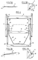
- the bed frame 1 partially shown in Figure 1, has two longitudinal sections 10 formed of metal hollow tubes of square section. Between these profiles are provided two transverse plates 11 and 12.
- each rod arranged in a vertical plane, is mounted on the internal side of the profiles 10, which means that the two rods 3 face each other. They are made integral with the profiles by means of fastening parts 30.
- Each rod is pierced with a series of holes 31 with a horizontal axis distributed regularly over the entire length.
- these holes can be distributed unevenly, so that the extension can be installed in predetermined positions.
- the extension 2 comprises two longitudinal and parallel sections 20, joined together at one of their ends, by a transverse plate 21.
- the profiles 20 have a "U" shaped section, the base 202 of which is arranged vertically, that is to say parallel to the rods 3. They are arranged in such a way so that their wings 201 are opposite each other. Profiles 20 can slide along the rods 3, the wings 201 being arranged on either side of the edges lower and upper rods 3.
- each profile 20 comprises at the base 202, a transverse hole 200 with a horizontal axis.
- a transverse hole 200 with a horizontal axis.
- the two sections 20 are provided, on the external face of their base 202, that is to say on their opposite sides, of a part 5, for example in plastic material.
- this part has two horizontal lower 53 and upper 52 walls which are connected firstly by a curvilinear wall element 54 and secondly by the lateral face 51.
- an oblong bore 50 is pierced longitudinally, arranged obliquely.
- the lower part of this hole is disposed on the side of the section 20 and, advantageously, the longitudinal and parallel edges of the bore form an angle ⁇ of approximately 45 ° with the vertical.
- the locking means consist of a metal wire stirrup 4, general shape of "U”. This stirrup has a base 40 which extends parallel and to near cross member 21 of the extension.
- the ends of the base 40 are continued by two oblique parts 41 forming an obtuse angle with it. These two parts are each connected to a lateral branch 42 which extends parallel to the profiles 20 and to the rods 3.
- the ends free 43 of these branches are folded at right angles to be able to penetrate the holes 31 and 200 previously cited, thus realizing the locking of the extension relative to the bed frame (see figure 2).
- These ends 43 aligned with respect to each other, materialize a pivot axis XX '.
- the entire stirrup is arranged in the same plane and that the lateral branches 42 pass through the bore 50 provided in each part 5.
- the parts 41 can form with the branches 42 a certain angle in a vertical plane, so that the base 40 is in a plane different from that ends 43.
- the base 40 is actuated in the direction of the arrow f (FIGS. 4 and 7A) so as to cause the pivoting movement of the stirrup upwards, around the axis XX 'mentioned above.
- each lateral branch 42 is forced to move upwards along the bores 50 which act as ramps.
- the branches 41 and 42 come together under the jamming effect caused by the angle a of each bore (FIG. 7B).
- the parts 5 are arranged substantially at a third of the distance between the axis XX 'and the part 40 of the stirrup, on the side of the holes 200. This position can vary in depending on the caliper travel desired, the flexibility of the caliper wire and the stroke required to block the extension at the ends 43.
- This device can, of course, be used for a bed extension, but also for the extension of a leg support, or any piece of furniture having a mobile extension in translation.
Landscapes
- Invalid Beds And Related Equipment (AREA)
- Data Exchanges In Wide-Area Networks (AREA)
- Specific Sealing Or Ventilating Devices For Doors And Windows (AREA)
- Extensible Doors And Revolving Doors (AREA)
- Ladders (AREA)
- Furniture Connections (AREA)
- Closing And Opening Devices For Wings, And Checks For Wings (AREA)
- Lock And Its Accessories (AREA)
- Drawers Of Furniture (AREA)
Claims (8)
- Vorrichtung für die Blockierung/Entriegelung in der Verschiebungsrichtung einer Verlängerung (2) eines Möbelstückes (1), wie zum Beispiel einem Bett oder einem Sessel, in dem die Verlängerung (2) zwei parallele Längsprofile (20) aufweist, welche auf mit dem Möbelstück (1) fest verbundenen Schienen (3) gleiten können, und in der die Profile (2) jeweils eine quer verlaufende Bohrung (200) aufweisen, während die Schienen (3) jeweils eine Reihe von gleichartigen Bohrungen (31) enthalten, so daß die Profile (20) gegenüber den Schienen (3) so angeordnet werden können, daß die Bohrungen (200, 31) zusammenfallen und dadurch die Einführung einer Blockierung ermöglichen,
dadurch gekennzeichnet, daß
diese Blockiermittel aus einem Bügel (4) aus einem weitgehend U-förmigen und elastisch verformbaren Draht bestehen, dessen freie Enden (43) umgebogen sind, damit sie in die Bohrungen (200, 31) eingreifen können, und dadurch, daß auf jedem der Profile (20) Mittel (50) vorgesehen sind, welche eine Rampe bilden und mit einem seitlichen Schenkel (42) des U-förmigen Bügels (4) zusammenwirken und so geformt sind, daß eine auf den Bügel (4) ausgeübte Kraft, durch welche er um die von den umgebogenen Enden (43) um die Achse (XX') gekippt wird, eine Verformung des Bügels bewirkt, durch die die umgebogenen Enden (43) aus einer der Bohrungen (31) der Bohrungen (200, 31) herausgezogen und damit die Entriegelung der Blockierung der Verlängerung ermöglicht wird, während eine Entlastung dieser Kraft die entgegensetzte Bewegung bewirkt, daß heißt, die Einführung der Enden in die Bohrung (31) und die Verriegelung der Verlängerung (2). - Vorrichtung nach Anspruch 1,
dadurch gekennzeichnet, daß
die die Rampe bildenden Mittel (50) aus einem Langloch bestehen, welches in einem mit den Profilen (20) fest verbundenen Teil (5) ausgebildet ist. - Vorrichtung nach Anspruch 2,
dadurch gekennzeichnet, daß
die Bohrung (50) ein Querloch ist, dessen unteres Ende an den Profilen angeordnet ist. - Vorrichtung nach Anspruch 3,
dadurch gekennzeichnet, daß
die parallelen Längskanten der Bohrung (50) gegenüber der Senkrechten einen Winkel von etwa 45° bilden. - Vorrichtung nach einem der Ansprüche 1 bis 4,
dadurch gekennzeichnet, daß
die Profile (20) einen U-förmigen Querschnitt haben, und dadurch, daß die mit dem Möbelstück fest verbundenen Schienen zwischen den Schenkeln (200) dieses U-förmigen Querschnitts angeordnet sind. - Vorrichtung nach einem der Ansprüche 1 bis 5,
dadurch gekennzeichnet, daß
die Basis (40) des U-förmigen Bügels (4) einen Bedienungsgriff bildet. - Vorrichtung nach einem der Ansprüche 1 bis 6,
dadurch gekennzeichnet, daß
dieser U-förmige Bügel (4) in dem Raum zwischen zwei Profilen (20) der Verlängerung (2) angeordnet ist. - Möbelstück mit einer gleitenden Verlängerung, welche mit einer Vorrichtung nach einem der Ansprüche 1 bis 7 ausgerüstet ist.
Applications Claiming Priority (2)
| Application Number | Priority Date | Filing Date | Title |
|---|---|---|---|
| FR9406031 | 1994-05-11 | ||
| FR9406031A FR2719754B1 (fr) | 1994-05-11 | 1994-05-11 | Dispositif de verrouillage/déverrouillage en translation d'une rallonge par rapport à un élément de mobilier et élément de mobilier ainsi équipé. |
Publications (2)
| Publication Number | Publication Date |
|---|---|
| EP0681799A1 EP0681799A1 (de) | 1995-11-15 |
| EP0681799B1 true EP0681799B1 (de) | 1998-08-05 |
Family
ID=9463282
Family Applications (1)
| Application Number | Title | Priority Date | Filing Date |
|---|---|---|---|
| EP95460021A Expired - Lifetime EP0681799B1 (de) | 1994-05-11 | 1995-05-05 | Blokiervorrichtung für eine Verlängerung Bezüglich eines Möbelstückes, und Möbelstück damit Ausgestattet |
Country Status (5)
| Country | Link |
|---|---|
| EP (1) | EP0681799B1 (de) |
| AT (1) | ATE169191T1 (de) |
| DE (1) | DE69503828T2 (de) |
| ES (1) | ES2122487T3 (de) |
| FR (1) | FR2719754B1 (de) |
Cited By (4)
| Publication number | Priority date | Publication date | Assignee | Title |
|---|---|---|---|---|
| US6654974B2 (en) | 2000-06-02 | 2003-12-02 | Hill-Rom Services, Inc. | Foot support for a patient support |
| US6757924B2 (en) | 1999-08-23 | 2004-07-06 | Hill-Rom Services, Inc. | Bed having a removable foot section |
| US7536734B2 (en) | 2005-01-31 | 2009-05-26 | Hill-Rom Services, Inc. | Birthing support apparatus |
| US7657953B2 (en) | 2005-11-17 | 2010-02-09 | Hill-Rom Services, Inc. | Birthing bed calf support |
Families Citing this family (5)
| Publication number | Priority date | Publication date | Assignee | Title |
|---|---|---|---|---|
| FR2815530B1 (fr) | 2000-10-23 | 2003-02-07 | Hill Rom Sas | Lit medicalise ou lit d'hopital equipe d'un plaque support coulissante |
| ES2241390B1 (es) * | 2002-08-28 | 2006-07-01 | Vicente Soto Martinez | Estructura para base de mueble de asiento. |
| WO2004112675A2 (en) | 2003-05-21 | 2004-12-29 | Hill-Rom Services, Inc. | Hospital bed |
| GB201208106D0 (en) * | 2012-05-09 | 2012-06-20 | Huntleigh Technology Ltd | Bed |
| EP4684772A1 (de) * | 2024-07-24 | 2026-01-28 | Hill-Rom Services, Inc. | Festbetterweiterungszubehör |
Family Cites Families (3)
| Publication number | Priority date | Publication date | Assignee | Title |
|---|---|---|---|---|
| FR1350758A (fr) * | 1962-12-17 | 1964-01-31 | Popula | Perfectionnements aux ferrures d'articulation pour cadres métalliques et analogues |
| US4070717A (en) * | 1976-04-28 | 1978-01-31 | Hoover Ball And Bearing Co. | Bed frame |
| SE426019B (sv) * | 1979-02-13 | 1982-12-06 | Nordpatent Ab | For anvendning vid eller i anslutning till en stol, exempelvis en fordonsstol eller en operatorsstol, avsedd anordning |
-
1994
- 1994-05-11 FR FR9406031A patent/FR2719754B1/fr not_active Expired - Fee Related
-
1995
- 1995-05-05 DE DE69503828T patent/DE69503828T2/de not_active Expired - Fee Related
- 1995-05-05 AT AT95460021T patent/ATE169191T1/de not_active IP Right Cessation
- 1995-05-05 EP EP95460021A patent/EP0681799B1/de not_active Expired - Lifetime
- 1995-05-05 ES ES95460021T patent/ES2122487T3/es not_active Expired - Lifetime
Cited By (10)
| Publication number | Priority date | Publication date | Assignee | Title |
|---|---|---|---|---|
| US6757924B2 (en) | 1999-08-23 | 2004-07-06 | Hill-Rom Services, Inc. | Bed having a removable foot section |
| US7073221B2 (en) | 1999-08-23 | 2006-07-11 | Hill-Rom Services, Inc. | Bed having a removable foot section |
| US7464421B2 (en) | 1999-08-23 | 2008-12-16 | Hill-Rom Services, Inc. | Bed having a removable foot section |
| US6654974B2 (en) | 2000-06-02 | 2003-12-02 | Hill-Rom Services, Inc. | Foot support for a patient support |
| US6854145B2 (en) | 2000-06-02 | 2005-02-15 | Hill-Rom Services, Inc. | Patient support |
| US6857153B2 (en) | 2000-06-02 | 2005-02-22 | Hill-Rom Services, Inc. | Patient support having a light assembly |
| US7469433B2 (en) | 2000-06-02 | 2008-12-30 | Hill-Rom Services, Inc. | Patient support with variable length actuator and release mechanism for lowering a sectional support surface |
| US7536734B2 (en) | 2005-01-31 | 2009-05-26 | Hill-Rom Services, Inc. | Birthing support apparatus |
| US7657953B2 (en) | 2005-11-17 | 2010-02-09 | Hill-Rom Services, Inc. | Birthing bed calf support |
| US7676868B2 (en) | 2005-11-17 | 2010-03-16 | Hill-Rom Services, Inc. | Birthing bed foot support release handle |
Also Published As
| Publication number | Publication date |
|---|---|
| DE69503828D1 (de) | 1998-09-10 |
| ATE169191T1 (de) | 1998-08-15 |
| FR2719754B1 (fr) | 1996-08-02 |
| EP0681799A1 (de) | 1995-11-15 |
| DE69503828T2 (de) | 1999-04-15 |
| FR2719754A1 (fr) | 1995-11-17 |
| ES2122487T3 (es) | 1998-12-16 |
Similar Documents
| Publication | Publication Date | Title |
|---|---|---|
| EP1326514B1 (de) | Bett mit gelenkigen schutzgitterelementen | |
| EP0182731A1 (de) | Hängevorrichtung zur Anordnung von individuellen kippbaren und nebeneinanderangeordneten Behältern | |
| EP0681799A1 (de) | Blokiervorrichtung für eine Verlängerung Bezüglich eines Möbelstückes, und Möbelstück damit Ausgestattet | |
| EP0365455A1 (de) | Transportvorrichtung für Patienten | |
| FR2773311A1 (fr) | Barriere pour lit, notamment pour lit a usage medical | |
| FR2938428A1 (fr) | Lit a barriere laterale composee de plusieurs barres s'etendant horizontalement | |
| EP1524399B1 (de) | Schutzgitter | |
| EP0734665B1 (de) | Bettgestell, mit übereinander angeordneten abklappbaren Rahmen, das mit Bodenstützen ausgestattet ist | |
| FR2696779A1 (fr) | Verrou automatique de sécurité pour volets roulants. | |
| EP0857448B1 (de) | Grillrost aus scharnierartig verbundenen Rostelementen | |
| CA1279959C (fr) | Canape covertible en lit | |
| FR2680955A1 (fr) | Lit a barriere escamotable. | |
| EP1721550A1 (de) | Krankenbett mit vollständiger Seitenlehne | |
| EP0803212B1 (de) | Ausziehbares Bett | |
| FR2815527A1 (fr) | Lit a elements de barrieres coulissants et articules | |
| FR2811579A1 (fr) | Support pour appareil respiratoire individuel portable destine au personnel d'intervention et notamment aux sapeurs-pompiers | |
| FR2640860A1 (en) | Support for slat of bedstead and fixing nail | |
| FR2823125A1 (fr) | Appareil pour grimper le long d'un arbre | |
| EP1201215B1 (de) | Krankenbett mit verschiebbarer Trägerplatte | |
| FR2691345A3 (fr) | Fond à lattes pour un article d'ameublement. | |
| BE882959R (fr) | Potence-support pour gril | |
| FR2758247A1 (fr) | Chaise, notamment une chaise d'ecole | |
| EP0041080A1 (de) | Ausziehbares Bett | |
| FR2844689A1 (fr) | Agencement d'assise modulable d'un siege transformable en couchage et element meublant obtenu | |
| EP1004239A1 (de) | Torsionsfester Angelrutenhalter |
Legal Events
| Date | Code | Title | Description |
|---|---|---|---|
| PUAI | Public reference made under article 153(3) epc to a published international application that has entered the european phase |
Free format text: ORIGINAL CODE: 0009012 |
|
| AK | Designated contracting states |
Kind code of ref document: A1 Designated state(s): AT CH DE DK ES GB IT LI |
|
| 17P | Request for examination filed |
Effective date: 19960418 |
|
| GRAG | Despatch of communication of intention to grant |
Free format text: ORIGINAL CODE: EPIDOS AGRA |
|
| RAP1 | Party data changed (applicant data changed or rights of an application transferred) |
Owner name: LE COUVIOUR SA |
|
| 17Q | First examination report despatched |
Effective date: 19971016 |
|
| GRAG | Despatch of communication of intention to grant |
Free format text: ORIGINAL CODE: EPIDOS AGRA |
|
| GRAH | Despatch of communication of intention to grant a patent |
Free format text: ORIGINAL CODE: EPIDOS IGRA |
|
| GRAH | Despatch of communication of intention to grant a patent |
Free format text: ORIGINAL CODE: EPIDOS IGRA |
|
| GRAA | (expected) grant |
Free format text: ORIGINAL CODE: 0009210 |
|
| AK | Designated contracting states |
Kind code of ref document: B1 Designated state(s): AT CH DE DK ES GB IT LI |
|
| REF | Corresponds to: |
Ref document number: 169191 Country of ref document: AT Date of ref document: 19980815 Kind code of ref document: T |
|
| REG | Reference to a national code |
Ref country code: CH Ref legal event code: EP |
|
| REF | Corresponds to: |
Ref document number: 69503828 Country of ref document: DE Date of ref document: 19980910 |
|
| REG | Reference to a national code |
Ref country code: CH Ref legal event code: NV Representative=s name: MICHELI & CIE INGENIEURS-CONSEILS |
|
| PG25 | Lapsed in a contracting state [announced via postgrant information from national office to epo] |
Ref country code: DK Free format text: LAPSE BECAUSE OF FAILURE TO SUBMIT A TRANSLATION OF THE DESCRIPTION OR TO PAY THE FEE WITHIN THE PRESCRIBED TIME-LIMIT Effective date: 19981105 |
|
| GBT | Gb: translation of ep patent filed (gb section 77(6)(a)/1977) |
Effective date: 19981109 |
|
| REG | Reference to a national code |
Ref country code: ES Ref legal event code: FG2A Ref document number: 2122487 Country of ref document: ES Kind code of ref document: T3 |
|
| PLBE | No opposition filed within time limit |
Free format text: ORIGINAL CODE: 0009261 |
|
| STAA | Information on the status of an ep patent application or granted ep patent |
Free format text: STATUS: NO OPPOSITION FILED WITHIN TIME LIMIT |
|
| 26N | No opposition filed | ||
| REG | Reference to a national code |
Ref country code: GB Ref legal event code: IF02 |
|
| PGFP | Annual fee paid to national office [announced via postgrant information from national office to epo] |
Ref country code: ES Payment date: 20080522 Year of fee payment: 14 Ref country code: DE Payment date: 20080514 Year of fee payment: 14 Ref country code: CH Payment date: 20080515 Year of fee payment: 14 |
|
| PGFP | Annual fee paid to national office [announced via postgrant information from national office to epo] |
Ref country code: AT Payment date: 20080417 Year of fee payment: 14 |
|
| PGFP | Annual fee paid to national office [announced via postgrant information from national office to epo] |
Ref country code: IT Payment date: 20080520 Year of fee payment: 14 |
|
| PGFP | Annual fee paid to national office [announced via postgrant information from national office to epo] |
Ref country code: GB Payment date: 20080506 Year of fee payment: 14 |
|
| REG | Reference to a national code |
Ref country code: CH Ref legal event code: PL |
|
| GBPC | Gb: european patent ceased through non-payment of renewal fee |
Effective date: 20090505 |
|
| PG25 | Lapsed in a contracting state [announced via postgrant information from national office to epo] |
Ref country code: LI Free format text: LAPSE BECAUSE OF NON-PAYMENT OF DUE FEES Effective date: 20090531 Ref country code: CH Free format text: LAPSE BECAUSE OF NON-PAYMENT OF DUE FEES Effective date: 20090531 Ref country code: AT Free format text: LAPSE BECAUSE OF NON-PAYMENT OF DUE FEES Effective date: 20090505 |
|
| PG25 | Lapsed in a contracting state [announced via postgrant information from national office to epo] |
Ref country code: GB Free format text: LAPSE BECAUSE OF NON-PAYMENT OF DUE FEES Effective date: 20090505 |
|
| PG25 | Lapsed in a contracting state [announced via postgrant information from national office to epo] |
Ref country code: DE Free format text: LAPSE BECAUSE OF NON-PAYMENT OF DUE FEES Effective date: 20091201 |
|
| REG | Reference to a national code |
Ref country code: ES Ref legal event code: FD2A Effective date: 20090506 |
|
| PG25 | Lapsed in a contracting state [announced via postgrant information from national office to epo] |
Ref country code: ES Free format text: LAPSE BECAUSE OF NON-PAYMENT OF DUE FEES Effective date: 20090506 |
|
| PG25 | Lapsed in a contracting state [announced via postgrant information from national office to epo] |
Ref country code: IT Free format text: LAPSE BECAUSE OF NON-PAYMENT OF DUE FEES Effective date: 20090505 |