EP0681818A2 - Méthode de contrôle d'un membre artificiel par des miopotentielles - Google Patents
Méthode de contrôle d'un membre artificiel par des miopotentielles Download PDFInfo
- Publication number
- EP0681818A2 EP0681818A2 EP95105327A EP95105327A EP0681818A2 EP 0681818 A2 EP0681818 A2 EP 0681818A2 EP 95105327 A EP95105327 A EP 95105327A EP 95105327 A EP95105327 A EP 95105327A EP 0681818 A2 EP0681818 A2 EP 0681818A2
- Authority
- EP
- European Patent Office
- Prior art keywords
- current
- value
- control
- proportional
- drive motor
- Prior art date
- Legal status (The legal status is an assumption and is not a legal conclusion. Google has not performed a legal analysis and makes no representation as to the accuracy of the status listed.)
- Granted
Links
Images


Classifications
-
- A—HUMAN NECESSITIES
- A61—MEDICAL OR VETERINARY SCIENCE; HYGIENE
- A61F—FILTERS IMPLANTABLE INTO BLOOD VESSELS; PROSTHESES; DEVICES PROVIDING PATENCY TO, OR PREVENTING COLLAPSING OF, TUBULAR STRUCTURES OF THE BODY, e.g. STENTS; ORTHOPAEDIC, NURSING OR CONTRACEPTIVE DEVICES; FOMENTATION; TREATMENT OR PROTECTION OF EYES OR EARS; BANDAGES, DRESSINGS OR ABSORBENT PADS; FIRST-AID KITS
- A61F2/00—Filters implantable into blood vessels; Prostheses, i.e. artificial substitutes or replacements for parts of the body; Appliances for connecting them with the body; Devices providing patency to, or preventing collapsing of, tubular structures of the body, e.g. stents
- A61F2/50—Prostheses not implantable in the body
- A61F2/68—Operating or control means
- A61F2/70—Operating or control means electrical
- A61F2/72—Bioelectric control, e.g. myoelectric
Definitions
- the invention relates to a method for the myoelectric proportional control of an electric motor-operated artificial limb, in particular a hand prosthesis, the voltage of the respective electrode signal being measured and fed to a control.
- DE 18 08 934 B2 discloses a myoelectric control circuit for proportionally controlled electromotively operated artificial limbs, in particular hand prostheses, the drive motor of the artificial limb being momentarily connected to the power source for the period of its activity.
- a DC voltage proportional to the myo voltage is superimposed on a sawtooth voltage of constant pulse height and pulse repetition frequency, the portions of this total voltage exceeding a constant threshold value each causing the drive motor to be connected to the current source.
- DE 22 36 969 B2 discloses a motor brake circuit for a myoelectric pulse-length-modulated control circuit of a proportionally controlled electromotively operated artificial limb, in particular a hand prosthesis, in which the myo-voltage amplified, rectified, integrated and sawtooth pulse voltage is superimposed on a constant pulse train frequency and pulse height.
- the superimposed voltage is applied to the input of a square-wave pulse generator in order to control the pulse duty factor of the square-wave generator pulses as a function of the amplitude of the myo-voltage taken off.
- the rectangular generator pulses are used to control a switch unit, via which a drive motor is connected to a power source in a pulse-like manner.
- the pulse-length-modulated square-wave generator pulses are fed via an amplifier to an integrator whose output voltage is proportional to the mean value of the duty cycle of the square-wave generator pulses, which is differentiated in a subsequent differentiator and controls a further switch in the switch unit, which short-circuits the armature winding of the drive motor in a pulse-like manner.
- This further switch only switches to signals of one polarity with a corresponding threshold value and can be formed by a biased transistor.
- DE 23 54 885 A discloses a myoelectric control circuit for pulse-length-modulated, proportionally controlled, electromotively operated artificial limbs, in particular hand prostheses, in which the myo-voltage is amplified, rectified and superimposed on a sawtooth voltage of constant frequency.
- the total voltage is applied to the input of a pulse generator, which is designed as a Schmitt trigger, in order to vary the pulse duty factor of the generator gate pulses as a function of the strength of the myo voltage removed.
- the generator pulses are used to control a switch unit, via which the drive motor is applied to a power source in pulses.
- a voltage proportional to the current of the drive motor can be supplied to the input of the pulse generator and / or a voltage proportional to the motor voltage can be supplied to the pulse generator as a bias.
- a measuring resistor is connected in series between the switch unit and the motor, the two terminals of which are connected to the inputs of a differential amplifier, the output of which is connected to the input of the pulse generator.
- Grip force and speed controls of electromechanical hand prostheses that are quasi proportional to the EMG (electromyogram) signal are thus known.
- the most common method used for speed control in DC motors is pulse width modulation (PWM).
- PWM pulse width modulation
- a periodic DC voltage is fed to the motor, the frequency of which is predominantly above the hearing range between 18 and 40 kHz.
- equivalent long voltage pulses are fed to the motor, which are integrated into an equivalent mean voltage value by the mechanical inertia of the motor armature. It has already been proposed to short-circuit the motor during the pauses in order to achieve better speed control. However, this increases the power consumption of the overall system.
- the object of the invention is to improve the method mentioned at the outset.
- a proportional speed control is carried out, the speed setpoint being assigned to the speed setpoint associated with the drive motor and in each case defined by a specific electrode voltage; the speed setpoint assigned to the respective measured electrode voltage; this speed setpoint is measured with the actual speed compared to the motor and fed as a control difference to a proportional integral controller (PI controller);
- PI controller the control deviation is converted into a pulse width modulation signal (PWM signal) in accordance with the parameters set and thus the drive motor is controlled, which thereby receives a speed proportional to the electrode voltage; the respective current current value of the drive motor is measured and compared with a predetermined current maximum, the PI controller being switched off when it is exceeded.
- PWM signal pulse width modulation signal
- a proportional grip force control is carried out, the grip force being built up step by step; the maximum grip force is divided into stages, the current electrode voltage corresponding to a certain number of stages; a certain pulse width modulation value (PWM value) and an associated current cut-off value are assigned to each stage; it is counted up from the counter reading 0 to the number of stages specified by the current electrode voltage, the PWM value selected by the counter being output with the current cut-off value equivalent to it; in parallel, the current of the drive motor is measured and compared with the current cut-off value that is output in each case; when this switch-off value is reached, the counter is increased by 1 and the next PWM value is output; if the counter reaches the number of steps specified by the electrode voltage, ie if the specified grip force is reached, the drive motor is switched off; the respective current current value of the drive motor is measured and compared with a predetermined current maximum, the drive motor also being switched off when
- both a speed control proportional to the EMG signal and a grip force control are possible.
- the two regulations in a system that works as follows: Two electrode signals are measured, averaged and fed to a lock that compares the signals with internally set switching thresholds and releases the corresponding motor direction.
- a mechanical grip switch the switching point of which is above the switching point of an automatic transmission, separates the system into two control loops. If the switching point is not reached, the system works with proportional speed control. If the switching point is exceeded, a switch is made to proportional grip force control.
- two electrode signals are measured, averaged and fed to a lock which compares the signals with internally set switching thresholds and releases the corresponding motor direction.
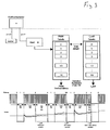
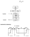
- a mechanical grip switch the switching point of which is above the switching point of an automatic transmission, separates the system into two control loops. If the switching point is not reached, the system works with proportional speed control ( Figure 2); if the switching point is exceeded, a switch is made to proportional grip force control (FIG. 3).
- the grip switch With proportional speed control, the grip switch is open; According to FIG. 1, the preferred electrode voltage is converted into a speed setpoint using a table.
- the corresponding table value represents the setpoint (setpoint speed) for the subsequent proportional-integral controller (PI controller).
- PI controller proportional-integral controller
- the resulting setpoint is compared with the measured actual engine speed and fed to a PI controller as a control difference.
- the engine speed is measured in the PWM gap as a feedback generator voltage.
- the control deviation is converted into a PWM signal in accordance with the set parameters and the motor bridge is thus controlled.
- the measured current motor current value is compared with a current maximum in a superimposed control circuit. If it is exceeded (the hand moves in the UP direction to the stop), the PI controller and thus the motor bridge are switched off.
- the grip force switch is operated by exceeding the set grip force, the system switches over to proportional grip force control.
- the grip strength is built up gradually, with the maximum grip force being divided into steps.
- the current electrode voltage corresponds to a certain number of steps.
- An internal program counter starts counting up two tables (PWM value and associated current cut-off value) from the counter reading 0 to the number of steps specified by the current electrode voltage.
- the PWM value selected by the counter is output.
- the motor current is measured and compared with the current cut-off value equivalent to the PWM value. When this switch-off value is reached, the counter is increased by 1 and the next PWM value is output.
- the specified grip force is reached; the engine is switched off.
- the amplitude of the electrode voltage is saved and set as a switching threshold for a possible hand grip. For this purpose, the muscle must be tightened accordingly to exceed this switching threshold.
- the counter reading is not set to 0, but to a higher table value when a predetermined switching threshold is exceeded due to the electrode voltage. This means that the maximum grip force is reached in less time and the motor is switched off.
- the motor is also switched off.
Landscapes
- Health & Medical Sciences (AREA)
- Cardiology (AREA)
- Oral & Maxillofacial Surgery (AREA)
- Transplantation (AREA)
- Engineering & Computer Science (AREA)
- Biomedical Technology (AREA)
- Heart & Thoracic Surgery (AREA)
- Vascular Medicine (AREA)
- Life Sciences & Earth Sciences (AREA)
- Animal Behavior & Ethology (AREA)
- General Health & Medical Sciences (AREA)
- Public Health (AREA)
- Veterinary Medicine (AREA)
- Prostheses (AREA)
- Control Of Direct Current Motors (AREA)
- Rehabilitation Tools (AREA)
- Lining Or Joining Of Plastics Or The Like (AREA)
- Electrotherapy Devices (AREA)
Applications Claiming Priority (2)
| Application Number | Priority Date | Filing Date | Title |
|---|---|---|---|
| DE4416509A DE4416509C1 (de) | 1994-05-10 | 1994-05-10 | Verfahren zur myoelektrischen Steuerung eines Kunstgliedes |
| DE4416509 | 1994-05-10 |
Publications (3)
| Publication Number | Publication Date |
|---|---|
| EP0681818A2 true EP0681818A2 (fr) | 1995-11-15 |
| EP0681818A3 EP0681818A3 (fr) | 1995-11-29 |
| EP0681818B1 EP0681818B1 (fr) | 2000-07-12 |
Family
ID=6517798
Family Applications (1)
| Application Number | Title | Priority Date | Filing Date |
|---|---|---|---|
| EP95105327A Expired - Lifetime EP0681818B1 (fr) | 1994-05-10 | 1995-04-08 | Méthode de contrôle d'un membre artificiel par des miopotentielles |
Country Status (11)
| Country | Link |
|---|---|
| EP (1) | EP0681818B1 (fr) |
| JP (2) | JPH0898853A (fr) |
| CN (1) | CN1116855C (fr) |
| AT (1) | ATE194477T1 (fr) |
| AU (1) | AU1786695A (fr) |
| CA (1) | CA2148577C (fr) |
| DE (2) | DE4416509C1 (fr) |
| DK (1) | DK0681818T3 (fr) |
| ES (1) | ES2079337T3 (fr) |
| RU (1) | RU2108768C1 (fr) |
| TW (1) | TW241202B (fr) |
Cited By (2)
| Publication number | Priority date | Publication date | Assignee | Title |
|---|---|---|---|---|
| WO1996041599A1 (fr) * | 1995-06-13 | 1996-12-27 | Otto Bock Orthopädische Industrie Besitz- Und Verwaltungskommanditgesellschaft | Procede de commande du frein d'un genou prothetique et prothese de cuisse |
| CN116214511A (zh) * | 2023-02-07 | 2023-06-06 | 南方科技大学 | 外肢体控制方法、装置、电子设备以及可读存储介质 |
Families Citing this family (17)
| Publication number | Priority date | Publication date | Assignee | Title |
|---|---|---|---|---|
| DE10311187B4 (de) * | 2003-03-12 | 2006-08-10 | Otto Bock Healthcare Gmbh | Orthopädietechnisches Hilfsmittel mit einer Verriegelungsvorrichtung |
| DE10311189B4 (de) * | 2003-03-12 | 2007-02-22 | Otto Bock Healthcare Gmbh | Orthopädietechnisches Hilfsmittel mit einer Verriegelungsvorrichtung |
| CN1838933B (zh) * | 2003-08-21 | 2010-12-08 | 国立大学法人筑波大学 | 穿着式动作辅助装置、穿着式动作辅助装置的控制方法和控制用程序 |
| DE102004048258A1 (de) | 2004-10-04 | 2006-04-20 | Trw Automotive Gmbh | Verfahren und Schaltungsanordnung zur Ansteuerung eines Elektromotors für einen Gurtaufroller |
| DE102005021412A1 (de) * | 2005-05-04 | 2006-11-09 | Otto Bock Healthcare Products Gmbh | System aus einem Liner mit einer myoelektrischen Elektrodeneinheit |
| EP1955679B1 (fr) | 2007-02-09 | 2013-11-06 | Semiconductor Energy Laboratory Co., Ltd. | Dispositif d'aide |
| US10842653B2 (en) | 2007-09-19 | 2020-11-24 | Ability Dynamics, Llc | Vacuum system for a prosthetic foot |
| CN101305939B (zh) * | 2008-05-26 | 2010-06-02 | 哈尔滨工业大学 | 一种用于仿人型肌电假手感觉反馈的电刺激器 |
| US8574178B2 (en) | 2009-05-26 | 2013-11-05 | The Hong Kong Polytechnic University | Wearable power assistive device for helping a user to move their hand |
| BR112012008097A2 (pt) * | 2009-09-02 | 2016-09-13 | Luis Armando Bravo Castillo | sistema e método de aquisição e processamento de sinais mioelétricos para controle de uma prótese de braço |
| CN101766510B (zh) * | 2009-12-18 | 2012-02-01 | 东南大学 | 基于肌电控制的机械假手的力触觉反馈及力度控制方法 |
| CN102883689B (zh) | 2010-05-06 | 2015-06-03 | 因文康公司 | 包括工具和该工具的安装装置的抓握辅助装置 |
| DK177559B1 (en) * | 2012-11-29 | 2013-10-14 | Invencon Aps | Aid grabbing tool with force activated gripping function |
| RU2627818C1 (ru) | 2016-03-15 | 2017-08-11 | Сергей Игоревич Щукин | Способ бионического управления техническими устройствами |
| CN105877745B (zh) * | 2016-03-29 | 2018-06-26 | 东北大学 | 基于表面肌电信号的直流电机速度控制系统及方法 |
| RU2677787C1 (ru) * | 2017-12-26 | 2019-01-21 | Общество с ограниченной ответственностью "Битроникс" | Способ для управления устройствами |
| CN113262088B (zh) * | 2021-05-27 | 2022-08-02 | 山东大学 | 一种具有力反馈的多自由度混合控制假肢手及控制方法 |
Family Cites Families (8)
| Publication number | Priority date | Publication date | Assignee | Title |
|---|---|---|---|---|
| US3418662A (en) * | 1965-03-31 | 1968-12-31 | Nat Res Dev | Prosthetic hand with improved control system for activation by electromyogram signals |
| AT283586B (de) * | 1967-12-29 | 1970-08-10 | Viennatone Hoergeraete Ing Koe | Myoelektrische Steuerschaltung für proportional gesteuerte elektromotorisch betätigte Kunstglieder |
| AT314075B (de) * | 1971-07-30 | 1974-03-25 | Viennatone Hoergeraete | Myoelektrische Steuerschaltung |
| AT323317B (de) * | 1972-11-08 | 1975-07-10 | Viennatone Hoergeraete | Myoelektrische steuerschaltung |
| AT328072B (de) * | 1974-05-27 | 1976-03-10 | Opt Ges Fur Orthopadietechnik | Sparschaltung fur myoelektrisch gesteuerte kunstglieder |
| AT340039B (de) * | 1975-09-18 | 1977-11-25 | Viennatone Gmbh | Myoelektrische steuerschaltung |
| GB2098489B (en) * | 1981-05-15 | 1986-04-09 | Hodgson Dr John Ashworth | Signal processing apparatus |
| CN85100043B (zh) * | 1985-04-01 | 1985-09-10 | 清华大学 | 假手自动换速增力机构 |
-
1994
- 1994-05-10 DE DE4416509A patent/DE4416509C1/de not_active Expired - Fee Related
- 1994-07-01 TW TW083105997A patent/TW241202B/zh not_active IP Right Cessation
-
1995
- 1995-04-08 AT AT95105327T patent/ATE194477T1/de active
- 1995-04-08 ES ES95105327T patent/ES2079337T3/es not_active Expired - Lifetime
- 1995-04-08 DK DK95105327T patent/DK0681818T3/da active
- 1995-04-08 EP EP95105327A patent/EP0681818B1/fr not_active Expired - Lifetime
- 1995-04-08 DE DE59508553T patent/DE59508553D1/de not_active Expired - Lifetime
- 1995-05-03 AU AU17866/95A patent/AU1786695A/en not_active Abandoned
- 1995-05-03 CA CA002148577A patent/CA2148577C/fr not_active Expired - Lifetime
- 1995-05-06 RU RU95107479A patent/RU2108768C1/ru active
- 1995-05-08 JP JP7109846A patent/JPH0898853A/ja active Pending
- 1995-05-09 CN CN95105468A patent/CN1116855C/zh not_active Expired - Lifetime
-
2005
- 2005-08-08 JP JP2005230161A patent/JP3923987B2/ja not_active Expired - Fee Related
Cited By (3)
| Publication number | Priority date | Publication date | Assignee | Title |
|---|---|---|---|---|
| WO1996041599A1 (fr) * | 1995-06-13 | 1996-12-27 | Otto Bock Orthopädische Industrie Besitz- Und Verwaltungskommanditgesellschaft | Procede de commande du frein d'un genou prothetique et prothese de cuisse |
| CN116214511A (zh) * | 2023-02-07 | 2023-06-06 | 南方科技大学 | 外肢体控制方法、装置、电子设备以及可读存储介质 |
| CN116214511B (zh) * | 2023-02-07 | 2024-04-16 | 南方科技大学 | 外肢体控制方法、装置、电子设备以及可读存储介质 |
Also Published As
| Publication number | Publication date |
|---|---|
| DK0681818T3 (da) | 2000-09-18 |
| EP0681818A3 (fr) | 1995-11-29 |
| CA2148577A1 (fr) | 1995-11-11 |
| DE59508553D1 (de) | 2000-08-17 |
| ATE194477T1 (de) | 2000-07-15 |
| ES2079337T1 (es) | 1996-01-16 |
| ES2079337T3 (es) | 2000-12-01 |
| AU1786695A (en) | 1995-11-16 |
| DE4416509C1 (de) | 1995-11-23 |
| EP0681818B1 (fr) | 2000-07-12 |
| RU2108768C1 (ru) | 1998-04-20 |
| TW241202B (en) | 1995-02-21 |
| RU95107479A (ru) | 1997-02-10 |
| CN1117839A (zh) | 1996-03-06 |
| CA2148577C (fr) | 2007-01-09 |
| JP2005334675A (ja) | 2005-12-08 |
| JP3923987B2 (ja) | 2007-06-06 |
| CN1116855C (zh) | 2003-08-06 |
| JPH0898853A (ja) | 1996-04-16 |
Similar Documents
| Publication | Publication Date | Title |
|---|---|---|
| EP0681818A2 (fr) | Méthode de contrôle d'un membre artificiel par des miopotentielles | |
| DE2751743C2 (de) | Verfahren und Regeleinrichtung zum Zumessen strömender Medien | |
| EP0448798B1 (fr) | Electro-bistouri | |
| DE2926378C2 (de) | Schaltungsanordnung zum Wiederanfahren eines verzögerten Induktionsmotors | |
| DE2811345C2 (de) | Druckregler für pneumatische Drücke, insbesondere in Fahrzeugen | |
| EP0705482B1 (fr) | Circuits de commande pour un contacteur-disjoncteur | |
| EP2171739B1 (fr) | Dispositif de commande pour un commutateur comprenant une bobine de collage et/ou de maintien et procédé de commande du courant qui circule à travers la bobine | |
| EP0296444B1 (fr) | Circuit de commande de la vitesse d'un moteur miniature à courant continu | |
| AT512995A1 (de) | Verfahren zur Regelung einer Stromquelle, sowie Stromquelle und Prozessregler hierfür | |
| EP0721692B1 (fr) | Convertisseur indirect | |
| DE102004045568A1 (de) | Steuer- und/oder Regelvorrichtung für eine elektromotorisch betätigbare Verstelleinrichtung zum Verstellen, vorzugsweise zum translatorischen Verschieben, wenigstens eines Möbelteils | |
| DE3841147A1 (de) | Verfahren zum ansteuern eines wechselstrom-motors sowie nach diesem verfahren ansteuerbarer wechselstrom-motor | |
| DE3343883A1 (de) | Verfahren und einrichtung zur zweipunktregelung eines laststromes | |
| EP0014369A1 (fr) | Régulateur de pression pour freins pneumatiques de véhicules, notamment de véhicules sur rails | |
| EP3381119B1 (fr) | Procédé de régulation en courant d'une charge inductive | |
| EP3226264A1 (fr) | Commande de courant comprenant un signal dither | |
| EP1880096B1 (fr) | Procede et dispositif de commande electrique d'une soupape au moyen d'un element de fermeture mecanique | |
| EP3672053A1 (fr) | Procédé de commande pour un convertisseur à résonance série en pont actif double et convertisseur à résonance série en pont actif double selon ledit procédé | |
| DE2731501C3 (de) | Regelanordnung für einen mit Reihenschluß-Nebenschluß-Umschaltung betriebenen Gleichstrommotor | |
| DE102013107792A1 (de) | Steuergerät für einen wandler und steuerverfahren | |
| EP0848309B1 (fr) | Dispositif de surveillance et limitation de la force de fermeture statique d'une porte | |
| EP0678271A2 (fr) | Circuit pour régler la puissance d'aspiration d'un aspirateur de poussière | |
| EP0678971B1 (fr) | Méthode pour inverser la direction de rotation pour un moteur CC sans balai à plan régime et moteur CC sans balai | |
| EP0498202B1 (fr) | Régulateur électromagnétique de position | |
| DE3335353C2 (de) | Regeleinrichtung mit einem Dreipunktschrittregler |
Legal Events
| Date | Code | Title | Description |
|---|---|---|---|
| PUAI | Public reference made under article 153(3) epc to a published international application that has entered the european phase |
Free format text: ORIGINAL CODE: 0009012 |
|
| PUAL | Search report despatched |
Free format text: ORIGINAL CODE: 0009013 |
|
| AK | Designated contracting states |
Kind code of ref document: A2 Designated state(s): AT BE CH DE DK ES FR GB IT LI NL SE |
|
| AK | Designated contracting states |
Kind code of ref document: A3 Designated state(s): AT BE CH DE DK ES FR GB IT LI NL SE |
|
| ITCL | It: translation for ep claims filed |
Representative=s name: MODIANO & ASSOCIATI S.R.L. |
|
| GBC | Gb: translation of claims filed (gb section 78(7)/1977) | ||
| EL | Fr: translation of claims filed | ||
| REG | Reference to a national code |
Ref country code: ES Ref legal event code: BA2A Ref document number: 2079337 Country of ref document: ES Kind code of ref document: T1 |
|
| 17P | Request for examination filed |
Effective date: 19951221 |
|
| TCNL | Nl: translation of patent claims filed | ||
| 17Q | First examination report despatched |
Effective date: 19980603 |
|
| GRAG | Despatch of communication of intention to grant |
Free format text: ORIGINAL CODE: EPIDOS AGRA |
|
| GRAG | Despatch of communication of intention to grant |
Free format text: ORIGINAL CODE: EPIDOS AGRA |
|
| GRAH | Despatch of communication of intention to grant a patent |
Free format text: ORIGINAL CODE: EPIDOS IGRA |
|
| GRAH | Despatch of communication of intention to grant a patent |
Free format text: ORIGINAL CODE: EPIDOS IGRA |
|
| GRAA | (expected) grant |
Free format text: ORIGINAL CODE: 0009210 |
|
| AK | Designated contracting states |
Kind code of ref document: B1 Designated state(s): AT BE CH DE DK ES FR GB IT LI NL SE |
|
| REF | Corresponds to: |
Ref document number: 194477 Country of ref document: AT Date of ref document: 20000715 Kind code of ref document: T |
|
| REG | Reference to a national code |
Ref country code: CH Ref legal event code: NV Representative=s name: BRAUN & PARTNER PATENT-, MARKEN-, RECHTSANWAELTE Ref country code: CH Ref legal event code: EP |
|
| GBT | Gb: translation of ep patent filed (gb section 77(6)(a)/1977) |
Effective date: 20000714 |
|
| REF | Corresponds to: |
Ref document number: 59508553 Country of ref document: DE Date of ref document: 20000817 |
|
| ET | Fr: translation filed | ||
| REG | Reference to a national code |
Ref country code: DK Ref legal event code: T3 |
|
| ITF | It: translation for a ep patent filed | ||
| REG | Reference to a national code |
Ref country code: ES Ref legal event code: FG2A Ref document number: 2079337 Country of ref document: ES Kind code of ref document: T3 |
|
| PLBE | No opposition filed within time limit |
Free format text: ORIGINAL CODE: 0009261 |
|
| STAA | Information on the status of an ep patent application or granted ep patent |
Free format text: STATUS: NO OPPOSITION FILED WITHIN TIME LIMIT |
|
| 26N | No opposition filed | ||
| REG | Reference to a national code |
Ref country code: GB Ref legal event code: IF02 |
|
| PGFP | Annual fee paid to national office [announced via postgrant information from national office to epo] |
Ref country code: BE Payment date: 20050421 Year of fee payment: 11 |
|
| PGFP | Annual fee paid to national office [announced via postgrant information from national office to epo] |
Ref country code: DK Payment date: 20050426 Year of fee payment: 11 |
|
| PGFP | Annual fee paid to national office [announced via postgrant information from national office to epo] |
Ref country code: CH Payment date: 20050503 Year of fee payment: 11 |
|
| PG25 | Lapsed in a contracting state [announced via postgrant information from national office to epo] |
Ref country code: LI Free format text: LAPSE BECAUSE OF NON-PAYMENT OF DUE FEES Effective date: 20060430 Ref country code: CH Free format text: LAPSE BECAUSE OF NON-PAYMENT OF DUE FEES Effective date: 20060430 Ref country code: BE Free format text: LAPSE BECAUSE OF NON-PAYMENT OF DUE FEES Effective date: 20060430 |
|
| PG25 | Lapsed in a contracting state [announced via postgrant information from national office to epo] |
Ref country code: DK Free format text: LAPSE BECAUSE OF NON-PAYMENT OF DUE FEES Effective date: 20060501 |
|
| REG | Reference to a national code |
Ref country code: DK Ref legal event code: EBP |
|
| REG | Reference to a national code |
Ref country code: CH Ref legal event code: PL |
|
| BERE | Be: lapsed |
Owner name: OTTO *BOCK ORTHOPADISCHE INDUSTRIE BESITZ- UND VER Effective date: 20060430 |
|
| PGFP | Annual fee paid to national office [announced via postgrant information from national office to epo] |
Ref country code: GB Payment date: 20140423 Year of fee payment: 20 |
|
| PGFP | Annual fee paid to national office [announced via postgrant information from national office to epo] |
Ref country code: DE Payment date: 20140430 Year of fee payment: 20 Ref country code: NL Payment date: 20140417 Year of fee payment: 20 Ref country code: ES Payment date: 20140417 Year of fee payment: 20 Ref country code: SE Payment date: 20140423 Year of fee payment: 20 Ref country code: IT Payment date: 20140424 Year of fee payment: 20 Ref country code: AT Payment date: 20140417 Year of fee payment: 20 Ref country code: FR Payment date: 20140416 Year of fee payment: 20 |
|
| REG | Reference to a national code |
Ref country code: DE Ref legal event code: R071 Ref document number: 59508553 Country of ref document: DE |
|
| REG | Reference to a national code |
Ref country code: NL Ref legal event code: V4 Effective date: 20150408 |
|
| REG | Reference to a national code |
Ref country code: NL Ref legal event code: V4 Effective date: 20150408 |
|
| REG | Reference to a national code |
Ref country code: GB Ref legal event code: PE20 Expiry date: 20150407 |
|
| REG | Reference to a national code |
Ref country code: AT Ref legal event code: MK07 Ref document number: 194477 Country of ref document: AT Kind code of ref document: T Effective date: 20150408 |
|
| REG | Reference to a national code |
Ref country code: SE Ref legal event code: EUG |
|
| REG | Reference to a national code |
Ref country code: ES Ref legal event code: FD2A Effective date: 20150626 |
|
| PG25 | Lapsed in a contracting state [announced via postgrant information from national office to epo] |
Ref country code: ES Free format text: LAPSE BECAUSE OF EXPIRATION OF PROTECTION Effective date: 20150409 Ref country code: GB Free format text: LAPSE BECAUSE OF EXPIRATION OF PROTECTION Effective date: 20150407 |