EP0681982A1 - Procédé et dispositif pour sectionner le ruban de fibres à une machine textile livrant du ruban de fibres - Google Patents
Procédé et dispositif pour sectionner le ruban de fibres à une machine textile livrant du ruban de fibres Download PDFInfo
- Publication number
- EP0681982A1 EP0681982A1 EP95105796A EP95105796A EP0681982A1 EP 0681982 A1 EP0681982 A1 EP 0681982A1 EP 95105796 A EP95105796 A EP 95105796A EP 95105796 A EP95105796 A EP 95105796A EP 0681982 A1 EP0681982 A1 EP 0681982A1
- Authority
- EP
- European Patent Office
- Prior art keywords
- sliver
- clamping
- guide channel
- pair
- point
- Prior art date
- Legal status (The legal status is an assumption and is not a legal conclusion. Google has not performed a legal analysis and makes no representation as to the accuracy of the status listed.)
- Granted
Links
Images


Classifications
-
- B—PERFORMING OPERATIONS; TRANSPORTING
- B65—CONVEYING; PACKING; STORING; HANDLING THIN OR FILAMENTARY MATERIAL
- B65H—HANDLING THIN OR FILAMENTARY MATERIAL, e.g. SHEETS, WEBS, CABLES
- B65H67/00—Replacing or removing cores, receptacles, or completed packages at paying-out, winding, or depositing stations
- B65H67/04—Arrangements for removing completed take-up packages and or replacing by cores, formers, or empty receptacles at winding or depositing stations; Transferring material between adjacent full and empty take-up elements
- B65H67/0428—Arrangements for removing completed take-up packages and or replacing by cores, formers, or empty receptacles at winding or depositing stations; Transferring material between adjacent full and empty take-up elements for cans, boxes and other receptacles
-
- B—PERFORMING OPERATIONS; TRANSPORTING
- B65—CONVEYING; PACKING; STORING; HANDLING THIN OR FILAMENTARY MATERIAL
- B65H—HANDLING THIN OR FILAMENTARY MATERIAL, e.g. SHEETS, WEBS, CABLES
- B65H67/00—Replacing or removing cores, receptacles, or completed packages at paying-out, winding, or depositing stations
- B65H67/04—Arrangements for removing completed take-up packages and or replacing by cores, formers, or empty receptacles at winding or depositing stations; Transferring material between adjacent full and empty take-up elements
- B65H67/0428—Arrangements for removing completed take-up packages and or replacing by cores, formers, or empty receptacles at winding or depositing stations; Transferring material between adjacent full and empty take-up elements for cans, boxes and other receptacles
- B65H67/0434—Transferring material devices between full and empty cans
-
- B—PERFORMING OPERATIONS; TRANSPORTING
- B65—CONVEYING; PACKING; STORING; HANDLING THIN OR FILAMENTARY MATERIAL
- B65H—HANDLING THIN OR FILAMENTARY MATERIAL, e.g. SHEETS, WEBS, CABLES
- B65H2701/00—Handled material; Storage means
- B65H2701/30—Handled filamentary material
- B65H2701/31—Textiles threads or artificial strands of filaments
Definitions
- the invention relates to a method and a device for separating a sliver on a textile machine delivering sliver.
- a textile machine can be a combing machine, carding machine, draw frame.
- the textile machine delivering the sliver stores the delivered sliver in cans. A separation of the sliver becomes necessary when the can has reached the filling level and has to be exchanged for an empty can.
- German application P 43 08 606.3 it is proposed to separate the fiber sliver in the area between the pair of calender rolls and the sliver guide channel of a turntable. From this point of view, a separator is placed in this area.
- the separator described has a clamping device consisting of a gripper with a control device and, furthermore, a separating device with a separating means, for example a circular knife, as an independently acting working means. Clamping device and separating device can be arranged on a common feed device.
- the stationary sliver is clamped in its conveying direction by means of the clamping device and then with the mechanical one Separating agent of the separating device separated.
- the function of the isolator requires a high level of structural complexity both for a clamping device and for a separating device.
- the object of the invention is to avoid the disadvantage of the prior art and to noticeably reduce the effort for a separator.
- a separation of the sliver is necessary when the can at a filling station is filled and a can change is necessary.
- the separation between the pair of calender rollers and the strip guide channel has proven to be expedient.
- the sliver is transported into the belt guide channel of a turntable by means of a pair of calender rollers and placed in a can.
- the method assumes that the transport of the sliver on the pair of calenders is stopped at the textile machine delivering the sliver. This means that working elements such as a turntable, can or traversing device of a filling station for Jugs are also stopped.
- the jug in the filling position comes to a standstill. This position at standstill is the standstill position of the jug.
- the separation point of the sliver should be between the pair of calender rollers and the opening of the sliver guide channel.
- the method according to the invention is based on the fact that, before the sliver is cut, the separation point to be formed is distorted by means of a clamping device, so that a draft point is formed in the sliver.
- the draft point represents a thin point in the cross section of the sliver. This draft point is separated by a subsequent separation process.
- a delay device is formed in several steps by means of the clamping device.
- the clamping device advantageously clamps the sliver at least at a distance below the clamping line of the pair of calenders that is greater than the stack length of the sliver.
- the clamping device which clamps the sliver, is subsequently displaced on a displacement path.
- the displacement path can be arranged transversely to the conveying direction of the sliver. But it can also be arranged in the direction of the tape guide channel.
- the clamping device is guided correspondingly far on the displacement path. If a strong distortion is desired, the clamping device is guided into a wide position compared to a position with less distortion.
- the delay point created is separated by a subsequent separation process.
- This separation process can be carried out by moving the filled can, which is at a standstill position.
- the fiber sliver deflected between the pair of calenders and the tape guide channel, including the drafting point is returned in the conveying direction of the fiber sliver and separated further at the drafting point when the can is moved further.
- the separate beginning of the belt which hangs on the pair of calender rolls, is positioned exactly in the conveying direction to the belt guide channel. In contrast to the known prior art, this facilitates the restart of the textile machine. Placing the beginning of the tape on the edge of the tape guide channel is avoided. Furthermore, the separated fibers are not sprayed off.
- Flat cans are used as a means of displacement the existing traversing device can be used and / or an additional means of transport for flat cans to enable the displacement.
- the separation process for the delay point can be carried out with a mechanically or pneumatically separating means if this should be used. There is no need to move the jug for the purpose of separating.
- sliver of different materials and different stack lengths can be processed.
- the invention takes this aspect into account in an alternative, wherein the clamping device clamps the fiber sliver and leads accordingly far on a displacement path until the fiber sliver separates between the clamping device and the pair of calender rolls.
- This is particularly useful when very short stack lengths and fine material, such as combed cotton, are used. With this material, there is no danger that the sliver will be deflected far and get stuck on the edge of the band guide channel after the separation.
- the device according to the invention for separating the sliver is the separating device.
- the separating device according to the invention is formed from a clamping device for fiber sliver and a displacement means for a jug.
- the clamping device is arranged next to the conveying direction of the sliver in the area of the pair of calender rolls and the band guide channel.
- the clamping device is also arranged at the beginning of a displacement path and is displaceable and can be fixed in position steps on the displacement path.
- the displacement path can advantageously lead transversely to the conveying direction of the sliver, but in another embodiment the displacement path can also be guided in the direction of the ribbon guide channel.
- Crucial for the arrangement of the Displacement is that a displacement point in the sliver can be formed by moving the clamping device.
- the clamping device has at least one clamping lever and one swivel arm as working means, each of which is connected to an adjusting device.
- the adjusting device includes a controllable drive device which is connected to a movable displacement mechanism, so that the clamping device can be displaced on the displacement path. To control the movement sequences between the clamping device and the displacement means, both are connected to a control of the textile machine.
- the clamping device can be constructed in that a pivot arm 9 and an angled drive arm 10 are mounted at their apex in an axis of rotation 13 and also a clamping lever 11 is supported at one end in the axis of rotation 13, so that there is a scissor-like arrangement between the pivot arm 9 and clamping lever 11 results.
- the swivel arm 9 and the clamping lever 11 are located opposite each other, next to the conveying direction of the sliver.
- an adjusting device 15 can be in engagement with the drive arm 10 via the axis 14, so that the drive arm 10 can be pivoted in the axis of rotation 13 with the pivot arm 9.
- the other adjusting device 17 is in engagement with the clamping lever 11 via the axis 16, so that the clamping lever 11 can be pivoted in the axis of rotation 13.
- the position of clamping lever 11 with stop 12 is adjustable by moving and fixing bolts 21 in slot 18. It can thus be set whether the stop 12 can be positioned near the edge of the tape guide channel or more to the center of the opening.
- the swivel arm 9 can be pivoted and fixed transversely to the conveying direction of the sliver onto the stop 12. This corresponds to the terminals.
- the setting of the swivel arm 9, ie its stroke, can be adjusted by arranging axis 14 in slot 23.
- the swivel arm 9, is guided transversely into the conveying direction of the sliver by means of its adjusting device 15, in the direction of the clamping lever 11.
- the sliver arm is gripped by the swivel arm and guided to the stop 12 of the clamping lever 11.
- the clamping lever 11 can be positioned on the edge of the tape guide channel 5 or next to the sliver.
- the sliver is clamped between the stop of the clamping lever 11 and the swivel arm 9. Both tools form a clamping point KS of the sliver.
- the swivel arm 9 and the clamping lever 11 can then be swiveled jointly transversely to the conveying direction of the sliver by means of the adjusting device 15 and the adjusting device 17 into an adjustable position of the displacement path S1.
- the sliver is deflected from the conveying direction. This means that a delay point can be created at the future separation point or a separation point can be created immediately. With this setting of the displacement path, it is possible to determine the degree of delay at the delay point.
- the clamping device After reaching the position level, the clamping device is opened and swivel arm 9 is returned to the starting position. After the separation process, the clamping lever 11 is returned to its starting position.
- the adjusting devices 15, 17 each have a control connection 19, 20 for a control device of the textile machine.
- the control device controls the above-mentioned movements via the adjustment devices 15 and 17 according to a control program and controls the displacement means at the required point in time.
- the sliver When a first position step is reached on the displacement path, the sliver is warped between the two clamping points, the pair of calender rollers and the clamping point of the clamping lever and swivel arm. Thus, a delay point is formed by the clamping device at the later separation point.
- the filled can under the turntable with its tape guide channel must be pushed by means of displacement means 80, so that there is a severing of the sliver at the delay point.
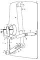
- FIG. 1 shows a section of a textile machine delivering a sliver.
- the range from a pair of calender rolls 2, 2 'to the placement of the sliver 3 in a can 8 is shown.
- a turntable 4 with its belt guide channel 5, which is rotatably arranged in a machine table, can be seen schematically.
- the machine table is characterized by an upper machine table 6 and a lower machine table 7.
- a textile machine that delivers sliver can be viewed as a combing machine, card, and draw frame.
- the term sliver in the following encompasses either a single sliver, a sliver doubled from several slivers, or a nonwoven fabric.
- the can 8 is located under the lower machine table 7.
- the can 8 has a movable can base 81 which is pressed against the spring force against the bottom of the can due to the sliver being laid down. If the conveying of the sliver on the pair of calenders 2, 2 'is stopped, this also means that the rotation of the turntable 4 and the movement of the can by the can stick or traversing device is stopped. In this situation, the can 8 is in the standstill position SP.
- a clamping device 1 is arranged next to the conveying direction of the sliver in the area between the pair of calender rollers 2, 2 'and the inlet opening of the sliver guide channel 5.
- the clamping device 1 is arranged approximately one stack length of the sliver to be processed below the pair of calender rolls 2, 2 '.
- the arrangement can also be deeper.
- a displacement means 80 for a can 8 is shown schematically. Clamping device 1 and displacement means 80 are connected to a control device St.
- the method assumes that the transport of the sliver on the pair of calenders 2, 2 'is stopped on the textile machine delivering the sliver.
- the one in the fill position located can 8 comes to a standstill. This position at a standstill is the standstill position SP of the can 8.
- the separation point of the sliver should lie between the pair of calender rollers 2, 2 'and the opening of the band guide channel 5.
- the method according to the invention assumes that the separation point to be formed is distorted by means of a clamping device 1 before the sliver is cut, so that a draft point is formed in the sliver.
- the draft point represents a thin point in cross section of the sliver. This draft point is separated by a subsequent separation process.
- a delay point is formed by means of the clamping device 1 in several steps.
- the clamping device 1 advantageously clamps the sliver at least at a distance below the clamping line of the pair of calender rolls 2, 2 'which is greater than the stack length of the sliver.
- the clamping device 1, which clamps the sliver is subsequently displaced on a displacement path S1 or S2.
- the displacement path S1 can be arranged transversely to the conveying direction of the sliver. But it can also be arranged in the direction of the tape guide channel (S2). In accordance with the desired degree of fiber sliver distortion at the separation point, the clamping device 1 is guided correspondingly far on the displacement path S1, S2.
- the clamping device 1 is guided into a wide position compared to a position with less distortion. With this adjustability, it is also possible to take into account different sliver materials. These positions can be marked on the displacement path S1, S2, so that the displacement path for the clamping device 1 is adjustable. If the clamping device 1 reaches the fixed position on the displacement path, the clamping device 1 is opened. The clamping device should expediently be returned to its starting position without influencing the band. With the clamping device 1 was achieved that the separation point was distorted at the separation point between the two nip points, pair of calender rolls and clamping device. A delay point was formed at the separation point.
- the delay point created is separated by a subsequent separation process.
- This separation process can be carried out by moving the filled can 8 which is in the standstill position (by means of displacement means 80).
- the fiber sliver deflected between the pair of calender rollers 2, 2 'and belt guide channel 5, including the drafting point is returned in the conveying direction of the fiber sliver and, when the can 8 is moved further, exactly at the Delay point separated.
- the can 8 is displaced by means of displacement means 80 into an end position of the can change, the end of the band is pulled out of the band guide channel 5 and hangs down on the edge of the can. It is achieved that the length of the band end always has the same length on the can 8.
- FIG. 2 shows the essential work equipment of the clamping device 1.
- the work equipment is arranged on the upper machine table 6.
- the inlet opening of the tape guide channel 5 can be seen.
- a pivot arm 9 with angled drive arm 10 and a clamping lever 11 with a stop 12 are arranged on both sides next to the band guide channel as essential working means in a plane above the band guide channel.
- the pivot arm 9 and drive arm 10 are mounted at their apex in the axis of rotation 13.
- the clamping lever 11 is also supported at one end in the axis of rotation 13. Both tools swivel arm 9 and clamping lever 11 are arranged in a scissor-shaped manner with respect to one another.
- the drive arm 10 is located above the axis 14 in engagement with an adjustment device 15.
- the adjustment device 15 can move the drive arm 10 and thus the swivel arm 9 via the engagement of the axis 14.
- the drive arm 10 has an elongated hole 23 so that the axis 14 is longitudinally adjustable.
- the stroke of the swivel arm 9 is thus adjustable.
- the adjusting device 15 can be, for example, a pneumatically operating cylinder with a movable piston rod, the piston rod of which can be controlled in terms of thrust or tension.
- the piston rod can be moved out so that the swivel arm 9 can be moved towards the stop 12.
- the adjustment device 15 can be controlled via the control connection 19, which is connected to a control unit St.
- the clamping lever 11 is engaged via the axis 16 with an adjusting device 17 which is mounted on a pin 21. By shifting the bolt 21 in the slot 18, it is possible to make the basic position of the clamping lever 11 adjustable and fixable.
- the adjusting device 17 has a control connection 20 for control purposes.
- the swivel arm 9, is guided transversely into the conveying direction of the sliver by means of its adjusting device 15, in the direction of the clamping lever 11.
- the clamping lever 11 can be positioned on the edge of the tape guide channel 5 or next to the sliver.
- the sliver is clamped between the stop of the clamping lever 11 and the swivel arm 9. Both tools form one Pinch point KS of the sliver.
- the swivel arm 9 and the clamping lever 11 can then be swiveled jointly transversely to the conveying direction of the sliver by means of the adjusting device 15 and the adjusting device 17 into an adjustable position of the displacement path S1.
- the sliver is deflected from the conveying direction. This means that a delay point can be created at the future separation point or a separation point can be created immediately. If a delay point is created, a separating process is generated in that the can 8 is displaced from its standstill position SP by means of displacement means 80.
- the jug movement pulls the sliver, which is ensured by jug 82.
- the tape breaks at the default point.
- the can is moved until the end of the band is pulled out of the band guide channel of the turntable and hangs on the edge of the can. With this setting of the displacement path, it is possible to determine the degree of delay at the delay point.
- the clamping device is opened and swivel arm 9 is returned to the starting position.
- clamping lever 11 is returned to its starting position.
- the adjusting devices 15, 17 each have a control connection 19, 20 for a control device of the textile machine.
- the control device controls the movements mentioned via the adjustment devices 15 and 17 according to a control program and controls the displacement means at the required point in time.
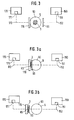
- FIG. 3 shows a clamping lever 110 and a swivel arm 90 in their starting position as essential working means. Both are arranged opposite each other in one plane, next to the belt guide channel 5. From the schematic top view of the tape guide channel 5 its inlet opening 50 is shown with sliver 3.
- the clamping lever 110 is connected to an adjusting device 170.
- the adjustment device 170 includes a controllable drive 171 and a mechanical displacement mechanism 172 for clamping levers 110.
- the swivel arm 90 is connected to an adjustment device 150.
- the adjustment device 150 includes a controllable drive 151 and a mechanical displacement mechanism 152 for the swivel arm 90.
- the can 8 When the can 8 has reached its filling state, which is determined, for example, by a belt length count on the line, a can change and thus a separation of the sliver is necessary.
- the sliver delivery on the line is at least briefly stopped for the duration of the separation process, but the sliver delivery of the pair of calender rolls is stopped.
- the swivel arm 90 Starting from the basic position of the work equipment according to FIG. 3, the swivel arm 90 is moved transversely to the conveying direction of the sliver by the adjusting device 150. The movement of the swivel arm leads to the clamping lever 110 or its stop. The sliver is clamped by clamping lever 110 and swivel arm 90 (FIG. 3a) and forms a clamping point KS.
- FIG. 3b further shows, the clamping lever 110 and the swivel arm 90 are moved laterally to the conveying direction of the belt, in continuation of the direction of movement of the swivel arm 90.
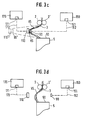
- FIG. 3c shows a side view with a view of the tape guide channel for a better understanding of the deflection of the tape.
- the fiber sliver 3 is deflected laterally to the sliver guide channel 5.
- the deflection of the sliver 3 by clamping lever 110 and swivel arm 90 takes place to such an extent that a warping of the sliver occurs between the clamping point KS and the clamping point of the pair of calender rolls 2, 2 '.
- the sliver 3 has a delay point VS, which corresponds to the later separation point TS.
- the shifting means 80 is actuated and the can is shifted.
- the deflected sliver is brought in the conveying direction by moving the can.
- the filled can 8 is moved further as a result of changing the can, the sliver is separated at the defined drafting point.
- Figure 3c shows another adjustable end position (dashed line).
- the lateral deflection of clamping lever 110 and pivot arm 90 continues up to a position of clamping lever 110 'and pivot arm 90'.
- the sliver is warped until it is separated. This corresponds to another alternative to the separation process.
- FIG. 4 shows the flat can 140 in the standstill position SP.
- the flat can 140 has a movable can base 141 which is pressed down. This shows the expert that the jug is full.
- the can mushroom 142 presses the sliver onto the turntable 70 and machine table.
- the turntable 70 has a belt guide channel 71 with an opening 100 and an opening 72.
- a clamping device 120 is positioned between the pair of calender rolls 60, 60' and the opening 100 of the belt guide channel 71.
- the clamping device is connected to a controller 160 via an operative connection. This control is also connected to the displacement means 83.
- FIG. 4a shows that the clamping device 120 has already worked, ie that it has formed a draft in the sliver. It is essential in the picture that the can 140 with the aid of the displacement means 83 is shifted from the standstill position SP.
- the displacement means 83 can be a traversing device and / or a means of transport for flat cans.
- the displacement means 83 displaces the flat can 140 according to FIG. 4b into a take-over position C. It can be seen that the end of the band has been pulled out of the band guide channel 71 of the turntable 70, the delay point being separated.
- the sliver end E hangs down on the end wall of the flat can 140.
- the sliver end E comes to rest in the central region of the end wall of the can. This is advantageous for subsequent automation solutions with regard to the transportation of the can and the attachment of the sliver end to further processing machines. Another advantage is that the band end E always hangs down from the flat can in a defined length.
Landscapes
- Spinning Or Twisting Of Yarns (AREA)
- Coiling Of Filamentary Materials In General (AREA)
- Replacing, Conveying, And Pick-Finding For Filamentary Materials (AREA)
- Preliminary Treatment Of Fibers (AREA)
Applications Claiming Priority (4)
| Application Number | Priority Date | Filing Date | Title |
|---|---|---|---|
| DE4416911 | 1994-05-13 | ||
| DE19944416911 DE4416911A1 (de) | 1994-05-13 | 1994-05-13 | Verfahren zum Positionieren eines Faserbandendes an einer befüllten Flachkanne und Vorrichtung zur Durchführung |
| DE4416947 | 1994-05-13 | ||
| DE19944416947 DE4416947A1 (de) | 1994-05-13 | 1994-05-13 | Vorrichtung zur Trennung des Faserbandes an einer Strecke |
Publications (2)
| Publication Number | Publication Date |
|---|---|
| EP0681982A1 true EP0681982A1 (fr) | 1995-11-15 |
| EP0681982B1 EP0681982B1 (fr) | 1998-04-08 |
Family
ID=25936576
Family Applications (2)
| Application Number | Title | Priority Date | Filing Date |
|---|---|---|---|
| EP95105796A Expired - Lifetime EP0681982B1 (fr) | 1994-05-13 | 1995-04-19 | Procédé et dispositif pour sectionner le ruban de fibres à une machine textile livrant du ruban de fibres |
| EP95105805A Expired - Lifetime EP0681983B1 (fr) | 1994-05-13 | 1995-04-19 | Procédé et dispositif pour positionner le bout d'un ruban de fibres sur un pot plein oblong |
Family Applications After (1)
| Application Number | Title | Priority Date | Filing Date |
|---|---|---|---|
| EP95105805A Expired - Lifetime EP0681983B1 (fr) | 1994-05-13 | 1995-04-19 | Procédé et dispositif pour positionner le bout d'un ruban de fibres sur un pot plein oblong |
Country Status (5)
| Country | Link |
|---|---|
| US (2) | US5581849A (fr) |
| EP (2) | EP0681982B1 (fr) |
| JP (2) | JP3484258B2 (fr) |
| CN (2) | CN1119223A (fr) |
| DE (2) | DE59501816D1 (fr) |
Cited By (3)
| Publication number | Priority date | Publication date | Assignee | Title |
|---|---|---|---|---|
| FR2794139A1 (fr) | 1999-05-27 | 2000-12-01 | Schlumberger Cie N | Dispositif de rupture d'un ruban de fibres textiles de forte cohesion et procede mis en oeuvre par ce dispositif |
| DE19548232C5 (de) * | 1995-03-11 | 2013-08-14 | Trützschler GmbH & Co Kommanditgesellschaft | Verfahren und Vorrichtung zum Trennen eines Faserbandes beim Kannenwechsel an einer Strecke |
| EP3336228A1 (fr) * | 2016-12-16 | 2018-06-20 | Rieter Ingolstadt GmbH | Procédé de fonctionnement d'un banc d'étirage ainsi que banc d'étirage destiné à l'étirage d'un ruban de fibre |
Families Citing this family (20)
| Publication number | Priority date | Publication date | Assignee | Title |
|---|---|---|---|---|
| US5774940A (en) * | 1996-07-19 | 1998-07-07 | North Carolina State University | Draftless sliver coiler packaging system for automated textile drafting system |
| DE19936703A1 (de) * | 1999-08-04 | 2001-02-08 | Truetzschler Gmbh & Co Kg | Vorrichtung zur Ablage des Faserbandes an einer Faserbandkanne, insbesondere Kanne mit länglichem Querschnitt |
| US20070069058A1 (en) * | 2002-02-07 | 2007-03-29 | Trutzschler Gmbh & Co. Kg | Apparatus on a spinning machine, especially a spinning preparation machine, for depositing and discharging fibre sliver |
| US20070063088A1 (en) * | 2002-02-07 | 2007-03-22 | Trutzchler Gmbh & Co. Kg | Apparatus in a spinning room for making available a can-less fibre sliver package (feed material) for a sliver-fed spinning machine, for example a draw frame |
| US20070069059A1 (en) * | 2002-02-07 | 2007-03-29 | Trutzschler Gmbh & Co. Kg | Apparatus in a spinning room for transporting a can-less fiber sliver package |
| US20080029637A1 (en) * | 2002-02-07 | 2008-02-07 | Trutzschler Gmbh & Co.Kg | Apparatus on a spinning room machine, especially a spinning preparation machine, for depositing and discharging fibre sliver |
| US20070063089A1 (en) * | 2002-02-07 | 2007-03-22 | Fa. Trutzschler Gmbh & Co.Kg | Apparatus on a spinning machine, especially a spinning preparation machine, for depositing fibre sliver |
| US7748658B2 (en) * | 2002-02-07 | 2010-07-06 | Truetzschler Gmbh & Co. Kg | Sliver discharge device |
| US20070068397A1 (en) * | 2002-02-07 | 2007-03-29 | Trutzschler Gmbh & Co. Kg | Apparatus in a spinning mill for transporting a can-less fibre sliver package |
| DE10205061A1 (de) * | 2002-02-07 | 2003-08-14 | Truetzschler Gmbh & Co Kg | Vorrichtung an einer Spinnereivorbereitungsmaschine, insbesondere Strecke oder Karde, bei der am Ausgang ein Faserband abgegeben und abgelegt wird |
| DE102004017441B4 (de) * | 2004-04-08 | 2011-09-01 | Rieter Ingolstadt Gmbh | Verfahren zur Faserverbundtrennung sowie Spinnereivorbereitungsmaschine |
| US7748315B2 (en) * | 2005-09-19 | 2010-07-06 | Truetzschler Gmbh & Co., Kg | System and method for packaging cotton sliver |
| DE102007016340A1 (de) * | 2007-04-03 | 2008-10-09 | TRüTZSCHLER GMBH & CO. KG | Vorrichtung an einer Spinnereimaschine, insbesondere Spinnereivorbereitungsmaschine, zur Ablage von Faserband |
| NL2010038C2 (en) * | 2012-12-21 | 2014-06-24 | Koni Bv | Shock absorber. |
| CN104032421B (zh) * | 2014-04-28 | 2017-02-22 | 何正中 | 一种新型绒条加工机 |
| DE102015105732A1 (de) * | 2015-04-15 | 2016-10-20 | TRüTZSCHLER GMBH & CO. KG | Bandablagevorrichtung zur Ablage eines Faserbandes in einer Kanne |
| CN106192097A (zh) * | 2015-04-30 | 2016-12-07 | 青岛云龙纺织机械有限公司 | 并条机双罗拉辊断条装置 |
| CN106835419B (zh) * | 2017-03-12 | 2019-04-30 | 夏津仁和纺织科技有限公司 | 功能性纤维棉网导出装置 |
| CN110565219B (zh) * | 2019-09-30 | 2024-04-16 | 天津宏大纺织机械有限公司 | 一种粗纱机棉条自动拉断装置 |
| CN115787276B (zh) * | 2022-11-14 | 2023-06-13 | 滁州霞客无染彩色纺有限公司 | 一种匀整并条机 |
Citations (5)
| Publication number | Priority date | Publication date | Assignee | Title |
|---|---|---|---|---|
| GB2039548A (en) * | 1979-01-03 | 1980-08-13 | Heberlein Hispano Sa | Device for severing a ropelike strand of fibres |
| DE3805203A1 (de) * | 1988-02-19 | 1989-08-31 | Fritz Stahlecker | Verfahren zum verarbeiten von faserband und maschinenanlage hierzu |
| FR2628085A1 (fr) * | 1988-03-05 | 1989-09-08 | Truetzschler & Co | Procede et appareil pour sectionner un ruban de fibres au changement de pot et pour commencer de nouveau la filee sur des machines de preparation a la filature telles que des cardes |
| EP0574659A1 (fr) * | 1992-06-17 | 1993-12-22 | Rieter Ingolstadt Spinnereimaschinenbau AG | Procédé et dispositif pour séparer un ruban de fibres délivré dans une boîte à un banc d'étirage |
| EP0615944A1 (fr) * | 1993-03-18 | 1994-09-21 | Rieter Ingolstadt Spinnereimaschinenbau AG | Procédé et dispositif pour la séparation de rubans de fibres sur un banc d'étirage |
Family Cites Families (30)
| Publication number | Priority date | Publication date | Assignee | Title |
|---|---|---|---|---|
| US3083416A (en) * | 1960-09-22 | 1963-04-02 | Toyo Boseki | Pneumatic cutting and introduction of textile sliver into can |
| NL120023C (fr) * | 1960-09-22 | |||
| US3354513A (en) * | 1964-01-23 | 1967-11-28 | Inst Textile Tech | Doffing apparatus |
| US3381342A (en) * | 1964-02-10 | 1968-05-07 | Warner Swasey Co | Method and apparatus for handling sliver |
| US3334385A (en) * | 1964-10-01 | 1967-08-08 | Maremont Corp | Coilers |
| DE1510428B2 (de) * | 1966-12-17 | 1974-01-24 | Schubert & Salzer Maschinenfabrik Ag, 8070 Ingolstadt | Verfahren und Vorrichtung zum Abreißen von Faserbändern an Bandablagevorrichtungen |
| DE2626651A1 (de) * | 1976-06-15 | 1977-12-29 | Barmag Barmer Maschf | Kabelfang- und -abschneidevorrichtung |
| DE2646313C2 (de) * | 1976-10-14 | 1986-07-03 | W. Schlafhorst & Co, 4050 Mönchengladbach | Verfahren und Vorrichtung zum Auswechseln von Faserbandkannen |
| DE2821325A1 (de) * | 1978-05-16 | 1979-11-22 | Schlafhorst & Co W | Verfahren und vorrichtung zum fuellen rotierender faserbandkannen |
| FR2450776A1 (fr) * | 1979-03-09 | 1980-10-03 | Rhone Poulenc Textile | Procede et dispositif de bambanage de cable de filaments textiles |
| JPS5617864A (en) * | 1979-07-18 | 1981-02-20 | Hara Shiyokuki Seisakusho:Kk | Stopping method of tube wheel at proper position in sliver drawer |
| EP0096168B1 (fr) * | 1982-06-08 | 1985-12-11 | Maschinenfabrik Rieter Ag | Dispositif pour couper une bande de fibres |
| DE3248711A1 (de) * | 1982-12-31 | 1984-07-05 | Hoechst Ag, 6230 Frankfurt | Verfahren und vorrichtung zum automatischen einlegen von endlosen faserkabeln |
| DE3324461C1 (de) * | 1983-07-07 | 1984-10-25 | Trützschler GmbH & Co KG, 4050 Mönchengladbach | Vorrichtung zum Trennen eines Faserbandes beim Kannenwechsel an Spinnereivorbereitungsmaschinen |
| DE3609198A1 (de) * | 1986-03-19 | 1987-09-24 | Neumuenster Masch App | Vorrichtung zum ablegen von spinnkabeln |
| DE3612133C2 (de) * | 1986-04-10 | 1995-02-16 | Truetzschler Gmbh & Co Kg | Bandführungskanal zwischen Ausgangswalzen und Kalanderwalzen an einer Spinnereivorbereitungsmaschine |
| IT1207807B (it) * | 1987-06-05 | 1989-06-01 | Bacciottini F Lli S N C Off | Dispositivo per l'interruzione a strappo di nastri di fibre tessili. |
| CS277008B6 (en) * | 1987-06-24 | 1992-11-18 | Schubert & Salzer Maschinen | Apparatus for stable fiber sliver automatic feeding |
| DE3837596A1 (de) * | 1988-11-05 | 1990-05-10 | Rosink Gmbh & Co Kg | Kannenstock |
| CH679773A5 (fr) * | 1989-11-07 | 1992-04-15 | Rieter Ag Maschf | |
| SK277982B6 (en) * | 1990-03-26 | 1995-09-13 | Elitex Cerveny Kostelec A S | Method of trapping, treatment and leading of sliver end into the spinning unit of open-end spinning machine and device for realization of this method |
| US5172453A (en) * | 1990-05-18 | 1992-12-22 | Murata Kikai Kabushiki Kaisha | Sliver can |
| CH681450A5 (fr) * | 1990-05-18 | 1993-03-31 | Rieter Ag Maschf | |
| IT1242376B (it) * | 1990-07-18 | 1994-03-04 | Loredana Brovelli | Vaso per nastri tessili |
| DE9014575U1 (de) * | 1990-09-07 | 1991-02-07 | Bahmer, Jakob | Vorrichtung zum Zuführen eines Faserbandes |
| DE4028365A1 (de) * | 1990-09-07 | 1992-03-12 | Jakob Bahmer | Vorrichtung zum zufuehren eines faserbandes |
| IT1241035B (it) * | 1990-12-21 | 1993-12-27 | Sant Andrea Novara Spa | Impianto e procedimento per lo stiro di nastri di fibre tessili, lavorante in continuo. |
| DE4123205C2 (de) * | 1991-07-10 | 1996-02-08 | Spinnereimaschinenbau Leisnig | Faserbandtrennung an Spinnereivorbereitungsmaschinen |
| DE9108621U1 (de) * | 1991-07-10 | 1991-09-05 | Großenhainer Textilmaschinenbau GmbH, O-8280 Großenhain | Vorrichtung zur Faserbandtrennung |
| DE4324948A1 (de) * | 1993-07-24 | 1995-01-26 | Rieter Ingolstadt Spinnerei | Verfahren zur Ablage des Faserbandes an einer Flachkanne und Vorrichtung zur Durchführung |
-
1995
- 1995-04-19 EP EP95105796A patent/EP0681982B1/fr not_active Expired - Lifetime
- 1995-04-19 EP EP95105805A patent/EP0681983B1/fr not_active Expired - Lifetime
- 1995-04-19 DE DE59501816T patent/DE59501816D1/de not_active Expired - Fee Related
- 1995-04-19 DE DE59502635T patent/DE59502635D1/de not_active Expired - Fee Related
- 1995-05-05 US US08/437,142 patent/US5581849A/en not_active Expired - Fee Related
- 1995-05-05 US US08/437,141 patent/US5647097A/en not_active Expired - Fee Related
- 1995-05-10 JP JP11170095A patent/JP3484258B2/ja not_active Expired - Fee Related
- 1995-05-12 CN CN95107200A patent/CN1119223A/zh active Pending
- 1995-05-12 JP JP11490895A patent/JP3485281B2/ja not_active Expired - Fee Related
- 1995-05-12 CN CN95107110A patent/CN1049024C/zh not_active Expired - Fee Related
Patent Citations (5)
| Publication number | Priority date | Publication date | Assignee | Title |
|---|---|---|---|---|
| GB2039548A (en) * | 1979-01-03 | 1980-08-13 | Heberlein Hispano Sa | Device for severing a ropelike strand of fibres |
| DE3805203A1 (de) * | 1988-02-19 | 1989-08-31 | Fritz Stahlecker | Verfahren zum verarbeiten von faserband und maschinenanlage hierzu |
| FR2628085A1 (fr) * | 1988-03-05 | 1989-09-08 | Truetzschler & Co | Procede et appareil pour sectionner un ruban de fibres au changement de pot et pour commencer de nouveau la filee sur des machines de preparation a la filature telles que des cardes |
| EP0574659A1 (fr) * | 1992-06-17 | 1993-12-22 | Rieter Ingolstadt Spinnereimaschinenbau AG | Procédé et dispositif pour séparer un ruban de fibres délivré dans une boîte à un banc d'étirage |
| EP0615944A1 (fr) * | 1993-03-18 | 1994-09-21 | Rieter Ingolstadt Spinnereimaschinenbau AG | Procédé et dispositif pour la séparation de rubans de fibres sur un banc d'étirage |
Cited By (4)
| Publication number | Priority date | Publication date | Assignee | Title |
|---|---|---|---|---|
| DE19548232C5 (de) * | 1995-03-11 | 2013-08-14 | Trützschler GmbH & Co Kommanditgesellschaft | Verfahren und Vorrichtung zum Trennen eines Faserbandes beim Kannenwechsel an einer Strecke |
| FR2794139A1 (fr) | 1999-05-27 | 2000-12-01 | Schlumberger Cie N | Dispositif de rupture d'un ruban de fibres textiles de forte cohesion et procede mis en oeuvre par ce dispositif |
| EP3336228A1 (fr) * | 2016-12-16 | 2018-06-20 | Rieter Ingolstadt GmbH | Procédé de fonctionnement d'un banc d'étirage ainsi que banc d'étirage destiné à l'étirage d'un ruban de fibre |
| DE102016124686A1 (de) * | 2016-12-16 | 2018-06-21 | Rieter Ingolstadt Gmbh | Verfahren zum Betreiben einer Strecke sowie eine Strecke zum Verziehen eines Faserbandes |
Also Published As
| Publication number | Publication date |
|---|---|
| CN1113524A (zh) | 1995-12-20 |
| DE59502635D1 (de) | 1998-07-30 |
| CN1119223A (zh) | 1996-03-27 |
| US5581849A (en) | 1996-12-10 |
| DE59501816D1 (de) | 1998-05-14 |
| CN1049024C (zh) | 2000-02-02 |
| EP0681982B1 (fr) | 1998-04-08 |
| EP0681983A1 (fr) | 1995-11-15 |
| JPH08151171A (ja) | 1996-06-11 |
| JP3484258B2 (ja) | 2004-01-06 |
| EP0681983B1 (fr) | 1998-06-24 |
| JPH08143223A (ja) | 1996-06-04 |
| US5647097A (en) | 1997-07-15 |
| JP3485281B2 (ja) | 2004-01-13 |
Similar Documents
| Publication | Publication Date | Title |
|---|---|---|
| EP0681982A1 (fr) | Procédé et dispositif pour sectionner le ruban de fibres à une machine textile livrant du ruban de fibres | |
| EP0770717B1 (fr) | Méthode et dispositif pour prélever et alimenter pneumatiquement un ruban sur une machine à filer du type open-end | |
| EP0303003B1 (fr) | Métier à filer à bout libre et procédé pour mettre en marche ledit métier | |
| DE2939644A1 (de) | Verfahren und vorrichtung zur beseitigung einer unregelmaessigkeit in einem faden | |
| DE4005752C2 (de) | Verfahren und Vorrichtung zum Vorbereiten zu spleißender Fadenenden | |
| DE3123494C2 (de) | Verfahren und Vorrichtung zum Aufwinden eines neu angesponnenen Fadens auf eine in eine Spulvorrichtung eingelegte Leerhülse | |
| DE3001918C2 (fr) | ||
| EP0452327B1 (fr) | Procede et dispositif de liaison automatique de fils | |
| DE3118382A1 (de) | Verfahren und vorrichtung zum unterbrechen und beginnen des spinnvorganges an einer offenend-spinnstelle | |
| EP3268173A1 (fr) | Unité de coupe comportant une lame pour couper au moins une fibre, notamment pour la fabrication d'ébauches de fibres | |
| EP0381995B1 (fr) | Procédé et dispositif de rattache pour un métier à filer à bout libre | |
| DE20212521U1 (de) | Klemmvorrichtung für Fadenlagen bei einer Multiaxialmaschine zum Vorlegen und Fixieren von Filamentscharen zu multiaxialen Fadengelegen sowie Multiaxialmaschine mit einer solchen Klemmvorrichtung | |
| DE3638110A1 (de) | Vorrichtung zum pneumatischen falschdrallspinnen | |
| DE2758064B2 (de) | Verfahren und Vorrichtung zum Beseitigen einer Unregelmäßigkeit im Faden an einer Spinnstelle einer Offen-End-Spinnvorrichtung | |
| EP3724386A1 (fr) | Machine à filer et dispositif de serrage | |
| WO2019115356A1 (fr) | Banc d'étirage et dispositif de serrage pour une machine à filer | |
| WO2019115346A1 (fr) | Banc d'étirage pour un métier à filer | |
| CH659495A5 (de) | Verfahren und vorrichtung zum abstellen und wiederanfahren einer offenend-spinnmaschine mit einer vielzahl von spinnvorrichtungen. | |
| DE3416456C2 (de) | Verfahren und Vorrichtung zur Inbetriebnahme einer Friktionsspinnmaschine | |
| CH693146A5 (de) | Vorrichtung zum Verbinden und Zuführen von Faserbändern. | |
| EP0826804B1 (fr) | Méthode et dispositif pour rattacher un fil dans un métier à filer à bout ouvert | |
| EP4208593A1 (fr) | Procédé pour l'exécution d'un processus de changement de pot de filature automatique au niveau d'un poste de filature d'un métier à filer, métier à filer, et dispositif de changement de pot de filature déplaçable | |
| DE2929353C2 (de) | Halteeinrichtung für den Schlingenfang an einem Knoteraggregat | |
| DD208634A5 (de) | Vorrichtung zur aufnahme eines streckrollenaggregates | |
| WO2007143866A1 (fr) | Séparation de ruban de fibres sur un appareil de dépôt de ruban |
Legal Events
| Date | Code | Title | Description |
|---|---|---|---|
| PUAI | Public reference made under article 153(3) epc to a published international application that has entered the european phase |
Free format text: ORIGINAL CODE: 0009012 |
|
| 17P | Request for examination filed |
Effective date: 19950419 |
|
| AK | Designated contracting states |
Kind code of ref document: A1 Designated state(s): DE ES FR IT |
|
| GRAG | Despatch of communication of intention to grant |
Free format text: ORIGINAL CODE: EPIDOS AGRA |
|
| GRAG | Despatch of communication of intention to grant |
Free format text: ORIGINAL CODE: EPIDOS AGRA |
|
| GRAH | Despatch of communication of intention to grant a patent |
Free format text: ORIGINAL CODE: EPIDOS IGRA |
|
| GRAH | Despatch of communication of intention to grant a patent |
Free format text: ORIGINAL CODE: EPIDOS IGRA |
|
| 17Q | First examination report despatched |
Effective date: 19970723 |
|
| GRAA | (expected) grant |
Free format text: ORIGINAL CODE: 0009210 |
|
| AK | Designated contracting states |
Kind code of ref document: B1 Designated state(s): DE ES FR IT |
|
| PG25 | Lapsed in a contracting state [announced via postgrant information from national office to epo] |
Ref country code: ES Free format text: THE PATENT HAS BEEN ANNULLED BY A DECISION OF A NATIONAL AUTHORITY Effective date: 19980408 |
|
| ET | Fr: translation filed | ||
| REF | Corresponds to: |
Ref document number: 59501816 Country of ref document: DE Date of ref document: 19980514 |
|
| ITF | It: translation for a ep patent filed | ||
| PLBE | No opposition filed within time limit |
Free format text: ORIGINAL CODE: 0009261 |
|
| STAA | Information on the status of an ep patent application or granted ep patent |
Free format text: STATUS: NO OPPOSITION FILED WITHIN TIME LIMIT |
|
| 26N | No opposition filed | ||
| PGFP | Annual fee paid to national office [announced via postgrant information from national office to epo] |
Ref country code: FR Payment date: 20010420 Year of fee payment: 7 |
|
| PG25 | Lapsed in a contracting state [announced via postgrant information from national office to epo] |
Ref country code: FR Free format text: LAPSE BECAUSE OF NON-PAYMENT OF DUE FEES Effective date: 20021231 |
|
| REG | Reference to a national code |
Ref country code: FR Ref legal event code: ST |
|
| PGFP | Annual fee paid to national office [announced via postgrant information from national office to epo] |
Ref country code: DE Payment date: 20080423 Year of fee payment: 14 |
|
| PGFP | Annual fee paid to national office [announced via postgrant information from national office to epo] |
Ref country code: IT Payment date: 20080421 Year of fee payment: 14 |
|
| PG25 | Lapsed in a contracting state [announced via postgrant information from national office to epo] |
Ref country code: DE Free format text: LAPSE BECAUSE OF NON-PAYMENT OF DUE FEES Effective date: 20091103 |
|
| PG25 | Lapsed in a contracting state [announced via postgrant information from national office to epo] |
Ref country code: IT Free format text: LAPSE BECAUSE OF NON-PAYMENT OF DUE FEES Effective date: 20090419 |