EP0682460B1 - Schnellverbindungsvorrichtung für Lautsprecher - Google Patents
Schnellverbindungsvorrichtung für Lautsprecher Download PDFInfo
- Publication number
- EP0682460B1 EP0682460B1 EP95105815A EP95105815A EP0682460B1 EP 0682460 B1 EP0682460 B1 EP 0682460B1 EP 95105815 A EP95105815 A EP 95105815A EP 95105815 A EP95105815 A EP 95105815A EP 0682460 B1 EP0682460 B1 EP 0682460B1
- Authority
- EP
- European Patent Office
- Prior art keywords
- loudspeaker
- annular body
- quick connection
- connection
- fixed seat
- Prior art date
- Legal status (The legal status is an assumption and is not a legal conclusion. Google has not performed a legal analysis and makes no representation as to the accuracy of the status listed.)
- Expired - Lifetime
Links
Images


Classifications
-
- H—ELECTRICITY
- H04—ELECTRIC COMMUNICATION TECHNIQUE
- H04R—LOUDSPEAKERS, MICROPHONES, GRAMOPHONE PICK-UPS OR LIKE ACOUSTIC ELECTROMECHANICAL TRANSDUCERS; ELECTRIC HEARING AIDS; PUBLIC ADDRESS SYSTEMS
- H04R1/00—Details of transducers, loudspeakers or microphones
- H04R1/02—Casings; Cabinets ; Supports therefor; Mountings therein
- H04R1/025—Arrangements for fixing loudspeaker transducers, e.g. in a box, furniture
Definitions
- This invention relates to a quick connection for loudspeakers, constituted substantially by an annular cylindrical body, either integral with or mountest on to the heavier back part constituting the magnet unit of loudspeakers, bayonet-engageable into a moulded seat which is obtained either directly on the plate of the doors or other suitable parts of the body, or on plastic details of support parts, such as for instance car parts or the like for car radio systems. It is provided with peripheral slanted or spiral flanges having the function of hooking its bayonet connection on said moulded seats.
- the annular body which engages with the magnet unit of loudspeakers, is applicable to said moulded seat thanks to an axial insertion movement followed by a rotation, which may be performed by hand or with mechanical tools and/or arms. No fasteners such as screws or the like are required.
- this invention comprises also connections that, once the whole is assembled, ensure a perfect and stable permanence in their correct position, and a perfect realization of electric connections.
- the annular cylindrical body may be also provided with a front part constituted by a peripheral band, with a free lower edge, on which band the front band of the diffusion cone of the loudspeaker engages.
- the lower edge of said peripheral band is free and participates in the connection getting in pressure relation with the peripheral zone adjoining the hole where said annular body is engaged.
- the configuration of present loudspeakers includes front structures peripherally arranged reatively to the outlet mouths of the diffusion cones, on which mouths coupling holes are provided for screws, rivets, bolts and the like. Thanks to these devices, the loudspeakers are connected to the spaces where they belong.
- EP-A-0198 359 discloses a quick connection for loudspeakers provided with a heavier back part or a magnet unit comprising: an annular body assembled to or integral with the heavier back part or the magnet unit of the loudspeaker; a fixed seat or structure, constituting the housing of the loudspeaker, provided with a through hole in which said loudspeaker is aligned and connected; a system of restrained hooking and locking said annular body to said fixed seat without utilization of complementary fastening means, and electric contacts of the loudspeaker and of a radio system, said contacts being in adherence when the loudspeaker is fastened to the seat, such as defined in the preamble of claim 1.
- Object of this invention is to eliminate the above reported drawbacks.
- a quick connection for loudspeakers wherein the system of restrained hooking and locking the annular body to the fixed seat without utilization of complementary fastening means, comprises:
- the connection of the loudspeakers to the supporting structures is applied on the heavier back part, opposite to the diffusion cones and corresponding to the magnet unit;
- the front part of loudspeakers, i.e. the diffusion cones is free from rigid connections;
- the coupling of fasteneres with the related and corresponding seats is by axial insertion and following rotation with bayonet-closing, followed by a final connection and by the closing of electric contacts.
- both parts may integrate a special electric connection: the quick connection is preferably made from plastic material or any other material having antivibration damping characteristics; the whole houses the coupled loudspeaker completely; the quick connection is bayonet-assembleable, either by hand or automatically, with no need for other tools.
- the advantages achieved by this invention lie essentially in that the connection of loudspeakers with their seats is obtained in a simple, quick, economical and safe way, the diffusion cones are not required to perform as supports; the freedom of the diffusion cones ensures the optimum operation both from the strictly mechanical point of view and from the more important acoustic point of view.
- the quick connection may be of the universal type, utilizable for corresponding types of loudspeakers and standardized holes to be obtained on the prepared walls of vehicles in general; the connection can be easily fastened in the corresponding spaces by simple alignment and bayonet-hooking rotation, while the possible lower edge gets in touch and pressure relation, with antivibration function, on the peripheral surface adjoining the coupling holes realizable on said prepared walls; the whole operation is quick, simple and economical.
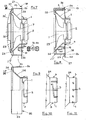
- said quick connection is substantially constituted by an annular body (1) so realized as to be assembleable to or substantially integral with the back part (2) and (2') of loudspeaker (7); more specifically, with the back magnet unit and possibly with the lower edge of the restraint basket of the acoustic diffusion cone.
- the annular body (1) in its non integral version, is realized according to the concept of a preferably but not limitedly plastic anchoring joint. With a suitable sizing, it allows to transform or to adapt even the traditional loudspeakers provided with a metal basket, not designed in view of an automatic assembly, into the type of quick connection wich is the subject matter of this invention.
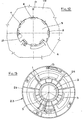
- the annular body (1) is provided along its peripheral edge with slanted or spiral flanges (3) which, during the assembly, get first in alignment relation with as many openings (4) obtained along edge (33) of the through hole (5) of seat (6) constituting the housing of a loudspeaker (7), and get afterwards in an engagement relation with parts (8) of the same seat, through a partial rotation of the same annular body (1).
- a loudspeaker (7) provided with its own annular body (1), either integral or rigidly mounted; gets in engagement and connection relation with a seat (6) by means of an axial coupling of flanges (3) with the corresponding openings (4) and a following partial rotation which causes said flanges to bayonet-fit into the walls of edge (8) of said seat.
- Seat (6), prepared to house loudspeaker (7) may be, for instance, either integral with or mounted on the car plates, such as those constituting the structure of the doors or other parts, or the parts from plastic material or the like constituting the accessory pockets or the back parts.
- Such seat (6) is preferably so shaped as to create a tile (9) acting as a water-barrier, preventing in this way the need of adding an external element to the structures.
- connection system has been so designed as to allow an automatic assembly, with no need for screws or other additional fasteners, which may be carried out either by hand by an operator, or mechanically through a robot (10).
- the mechanized connection system may be provided with dedicated assembly fitting means obtained on the front protection cover (11), which is removed by the same manipulator at the end of the assembly operation. This does not prevent the system from having one or several suitable assembly fitting means at any other point of the above component.
- connection assures a perfect flushness of the front part (42) of loudspeaker (7), thanks to the uniformity of the bearing on the fixed peripheral annular body (12), possibly realized from elastic material, the traction force being uniformly distributed across the bearing outer area, because of the absence of screws or the like, which, on the contrary, concentrate big stresses on individual points.
- This solution ensures less operation criticity and the anchoring of the loudspeakers in the heaviest point, corresponding to zone (2) of the magnet unit, ensuring the absence of projecting weights.
- This last condition is very important for the absorbtion and/or capacity of supporting shocks, even violent, as happens when one closes the doors, or the like.
- lid (11) if not removed, prevents the assembly of the finishing cover of the loudspeaker, as special interference zones have been created between the two parts on said lid.
- the elastic tangs (13) can be frontally unhooked from their seats (21) to allow the possible disassembly operations.
- the annular body (1) besides the already expounded characteristics, comprises a periferal end piece (14) on which a stirrup (15) engages which comprises the electric contacts (16) of loudspeaker (7).
- stirrup (15) is caused to enter the central hole (5) of seat (6); after which, in the sequential closing rotation (15), also stirrup (15) rotates until it gets in adherence relation with a second stirrup (18) located on an end piece (19) which originates from the surface of seat (6).
- Electric contacts (20) are provided also on the second stirrup (18), which connect with the wires of the radio system. The adherence between stirrups (15) and (18) causes also the adherence of the electric contacts (16) and (20), which close the whole circuit.
- the floating contact connection is suitable to accept the two movements which take place during the assembly operation.
- an additional contact is provided for the end-of-assembly electric functional control, by which it is possible to test directly the correctness of the assembly-electric connection operation.
- the quick connection for loudspeakers comprises, besides the above cylindrical annular body (1), a continuous peripheral front band (23).
- the annular body (1) and the peripheral band (23) are integral to one another and connect coaxially through an intermediate truncated-cone-shaped structure (24), which can substantially replace the restraint basket of the acoustic diffusion cone utilized by the current art.
- annular body (1) connects, as said, to the back part (2) of a loudspeaker (7)
- the front peripheral part (23') of said band (23) engages with the front strip (28) of the diffusion cone (29) of said loudspeaker (7).
- the peripheral slanted or spiral flanges (3) are always present, and said body configurated as described above constitutes always the real loadbearing structure of all the parts contituting the loudspeaker (7) and the means by which said loudspeaker is connectable to a support (110).
- the spiral flanges (3) get in alignment relation with as many openings (4), which afterwards get in engagement and connection relation with walls (8) of edge (33) of hole (5) by a partial rotation of the basket.
- the spiral of flanges (3) produces a pressure-closing of the bayonet-fitting type.
- the connecting flanges or teeth (3) may be obtained directly on the peripheral part of the magnet unit (2).
- the configuration of the central body (1) will be obviously without the annular part supporting special flanges (3), being limited to the part connected to the magnet unit (2).
- the corresponding coupling hole (5) obtained on support (110) will be adequate to the configuration of said magnet unit provided with spiral flanges (3).
- Said lock prevents the onset of possible vibrations and/or the so-called acoustic short-circuits; namely, it prevents the air stressed by the back part of the membrane from interferring with the air stressed by the front part of the same, avoiding phenomena of cancellation of the acoustic signals generated or the formation of interferences that might alterate said signals.
- the continuous peripheral front band (23) with the associated lower edge (26) has also the function of protecting the membrane of loudspeaker (7), the diffusion cone (29) and the electric contacts (16) (20), which are preferably, but not limitatively, obtained on stirrups (30) and (31) located, respectively, on the intermediate structure (24) of the quick connection and on wall (27) of the fixed support (110).
- contacts (16) (20) get in touch and engage with one another, connecting electrically and allowing the system to operate.
- loudspeaker (7) as a whole is completed by a front cover (32), which engages, through peripheral teeth (33), along the circumferential front seat (34) of the peripheral band (23). Also the connection of cover (32) with band (23) is substantially of the bayonet type, with axial alignment and subsequent rotation.
- cover (32) is removable by counter-rotation and axial slipping off.
- a finishing trim or grid (32') may be applied to the cover 32 in the same seat 34 and with the same rotation system, which trim or grid has a diameter greater than the system, forming a ledge relatively to the door panel of vehicles or the like.
- Such grid 32' is integral with the system or applied subsequently.
- the quick connection has a further advantage in that loudspeaker (7) inside it is more uniformely supported, both in the front and the back part, contrary to the present configurations.
- the quick connection may be of the universal type with respect to holes (5) to be made in the structure.
- said holes may be standardized, simplifying the moulding operations of supports (110), such as the doors of vehicles or the like.
- the back part of the connection is realized with standard external dimensions, while the middle and front part are realized with dimensions suitable for the restraint of the various models and/or types of loudspeakers.
- the so designed quick connection comprising the elastic tangs (13) and the electric connections (16), ensures a perfect and quick assembly of the whole, excluding possible human errors during the assembly stages.
Landscapes
- Physics & Mathematics (AREA)
- Engineering & Computer Science (AREA)
- Acoustics & Sound (AREA)
- Signal Processing (AREA)
- Audible-Bandwidth Dynamoelectric Transducers Other Than Pickups (AREA)
- Fittings On The Vehicle Exterior For Carrying Loads, And Devices For Holding Or Mounting Articles (AREA)
Claims (10)
- Schnellverbindung für Lautsprecher, welche mit einem schwereren Rückteil oder einer Magneteinheit (2) versehen sind, umfassend:- einen ringförmigen Körper (1), der mit dem schwereren Rückteil oder der Magneteinheit (2) des Lautsprechers (7) zusammengebaut oder in diesem integriert ist,- einen festen Sitz (6) oder Struktur (110), welche(r) das Gehäuse des Lautsprechers (7) bildet, der mit einer Durchgangsöffnung (5) versehen ist, in welcher der Lautsprecher (7) ausgerichtet und angefügt ist,- ein System des zurückhaltenden Einhängens und Verriegelns des ringförmigen Körpers (1) an dem festen Sitz (7) ohne Verwendung von komplementären Befestigungsmitteln, und- elektrische Kontakte (16) des Lautsprechers (7) und (20) eines Radiosystems, wobei die Kontakte (16, 20) aneinander anhängen, wenn der Lautsprecher (7) in dem Sitz (6) befestigt ist,dadurch gekennzeichnet, dass das System des zurückhaltenden Einhängens und Verriegelns des ringförmigen Körpers (1) an dem festen Sitz (7) umfasst:- abgeschrägte oder spiralförmige Flansche (3), die entlang der Umfangskante des ringförmigen Körpers (1) vorgesehen sind, und Öffnungen (4) und Eingriffsteile (8), die entlang der Kante (33) des festen Sitzes (6) vorgesehen sind; wobei die abgeschrägten oder spiralförmigen Flansche (3) des ringförmigen Körpers (1) in Bajonettverbindung mit den Eingriffsteilen (8) des festen Sitzes (6) durch axiales Koppeln der Flansche (3) an die entsprechenden Öffnungen (4) und teilweises Rotieren des ringförmigen Körpers (1) in Bajonettverbindung stehen, was die Flansche (3) veranlasst, in den Eingriffsteilen (8) Bajonett-gepasst zu sein; und- elastische Angeln (13), die auf dem ringförmigen Körper (1) vorgesehen sind, und entsprechende Sitze (21), die auf dem festen Sitz (6) vorgesehen sind; wobei die Angeln (13) in die Sitze (21) eingreifen, wenn die abgeschrägten oder spiralförmigen Flansche (3) des ringförmigen Körpers (1) in der Bajonettverbindung mit den Eingriffsteilen (8) des festen Sitzes (6) stehen.
- Schnellverbindung für Lautsprecher gemäß Anspruch 1, dadurch gekennzeichnet, dass der feste Sitz (6) mit einer Platte (9) versehen ist, die als eine Wasserbarriere wirkt.
- Schnellverbindung für Lautsprecher gemäß Anspruch 1 oder 2, dadurch gekennzeichnet, dass der Lautsprecher (7) mit einem Deckel (11) versehen ist und seine Entfernung verhindert wird, wenn die elastischen Angeln (13) außerhalb der entsprechenden Sitze (21) sind.
- Schnellverbindung für Lautsprecher gemäß irgendeinem der vorhergehenden Ansprüche, dadurch gekennzeichnet, dass der ringförmige Körper (1) mit einem ersten Bügel (15) versehen ist, welcher die elektrischen Kontakte (16) des Lautsprechers (7) enthält, durch ein Umfangs-Endstück (14) getragen wird; und entsprechend der feste Sitz (6) mit einem zweiten Bügel (18) versehen ist, welcher die elektrischen Kontakte (20) des Radiosystems enthält, durch ein Endstück (19) getragen wird; wobei der erste Bügel (15) in anhängender Relation zu dem zweiten Bügel (18) steht, was das Anhängen zwischen den elektrischen Kontakten (16, 20) , welche den elektrischen Schaltkreis schließen, bewirkt, wenn die abgeschrägten oder spiralförmigen Flansche (3) des ringförmigen Körpers (1) in Bajonettverbindung mit den Eingriffsteilen (8) des festen Sitzes (6) stehen.
- Schnellverbindung für Lautsprecher gemäß Anspruch 4, dadurch gekennzeichnet, dass die ersten (15) und die zweiten (18) Bügel mit zusätzlichen Kontakten für die Ende-des-Zusammenbaus-Elektrikverbindungskontrolle versehen sind.
- Schnellverbindung für Lautsprecher gemäß irgendeinem der vorhergehenden Ansprüche, dadurch gekennzeichnet, dass der ringförmige Körper (1) ein kontinuierliches Umfangsfrontband (23) umfasst, welches koaxial zu dem Körper (1) durch eine zwischenliegende Struktur (24) in der Form eines Kegelstumpfes verbunden ist, wobei das Umfangsfrontband (23) einen Umfangsfrontteil (23') aufweist, der in einem Frontstreifen (28) des Diffusionskonus (29) des Lautsprechers (7) eingreift, und eine untere Kante (26), die unter Druck optional mit einer zwischenliegenden Dichtung (38) in die Wand des Trägers (110) eingreift.
- Schnellverbindung für Lautsprecher gemäß Anspruch 6, dadurch gekennzeichnet, dass die untere Kante (26) verdünnt oder mit deformierbaren elastischen Angeln oder mit einer elastischen Dichtung (38) versehen ist.
- Schnellverbindung für Lautsprecher gemäß irgendeinem der vorhergehenden Ansprüche 6 bis 7, dadurch gekennzeichnet, dass die elektrischen Kontakte (16) des Lautsprechers (7) durch einen ersten Bügel (30) getragen werden, der sich auf der zwischenliegenden kegelstumpfförmigen Struktur (24) befindet, und die elektrischen Kontakte (20) des Radiosystems durch einen zweiten Bügel (31) getragen werden, der sich auf der Wand (27) des Trägers (110) befindet.
- Schnellverbindung für Lautsprecher gemäß irgendeinem der vorhergehenden Ansprüche 6 bis 8, dadurch gekennzeichnet, dass der Lautsprecher (7) mit einer Frontabdeckung (32) versehen ist, welche umfängliche Zähne (37) aufweist, die entlang des Umfangs-Frontsitzes (34) des Umfangsfrontbandes (23) durch eine bajonettartige Verbindung verbunden ist.
- Schnellverbindung für Lautsprecher gemäß irgendeinem der vorhergehenden Ansprüche 6 bis 8, dadurch gekennzeichnet, dass der Lautsprecher (7) mit einer Abschluss-Verkleidung oder Gitterabdeckung (32') versehen ist, die an die Abdeckung (32) angefügt ist, und einen Durchmesser aufweist, der größer als das Lautsprechersystem ist und an dem Umfangsfrontband (23) durch eine bajonettartige Verbindung angeschlossen ist.
Applications Claiming Priority (4)
| Application Number | Priority Date | Filing Date | Title |
|---|---|---|---|
| IT94RE000036 IT1269646B (it) | 1994-05-11 | 1994-05-11 | Attacco rapido per altoparlanti |
| ITRE940036 | 1994-05-11 | ||
| ITRE940108 | 1994-12-29 | ||
| IT94RE000108 IT1269664B (it) | 1994-12-29 | 1994-12-29 | Cestello per altoparlanti |
Publications (3)
| Publication Number | Publication Date |
|---|---|
| EP0682460A2 EP0682460A2 (de) | 1995-11-15 |
| EP0682460A3 EP0682460A3 (de) | 1998-01-14 |
| EP0682460B1 true EP0682460B1 (de) | 2007-08-08 |
Family
ID=26331971
Family Applications (1)
| Application Number | Title | Priority Date | Filing Date |
|---|---|---|---|
| EP95105815A Expired - Lifetime EP0682460B1 (de) | 1994-05-11 | 1995-04-19 | Schnellverbindungsvorrichtung für Lautsprecher |
Country Status (5)
| Country | Link |
|---|---|
| EP (1) | EP0682460B1 (de) |
| AT (1) | ATE369718T1 (de) |
| DE (1) | DE69535548T2 (de) |
| ES (1) | ES2292166T3 (de) |
| PT (1) | PT682460E (de) |
Families Citing this family (5)
| Publication number | Priority date | Publication date | Assignee | Title |
|---|---|---|---|---|
| DE10256970A1 (de) * | 2002-12-05 | 2004-06-24 | Delphi Technologies, Inc., Troy | Lautsprecheranordnung |
| WO2004077875A1 (en) * | 2003-02-28 | 2004-09-10 | Koninklijke Philips Electronics N.V. | Holding device for holding at least two separate electroacoustic transducers |
| EP2477417B1 (de) * | 2011-01-14 | 2013-09-25 | Mosel Türen Vertriebsges.mbH | Türblatt mit Haltemittel für ein elektronisches Gerät |
| WO2019022184A1 (ja) * | 2017-07-28 | 2019-01-31 | 日本精機株式会社 | 計器 |
| FR3097396B1 (fr) * | 2019-06-17 | 2021-05-14 | Psa Automobiles Sa | Dispositif de restitution sonore à boîtier et haut-parleur partiellement réalisés en technologie mid |
Family Cites Families (6)
| Publication number | Priority date | Publication date | Assignee | Title |
|---|---|---|---|---|
| US4439643A (en) * | 1979-04-02 | 1984-03-27 | Rene Schweizer | System assembly for mounting electrical apparatus on walls and ceilings |
| DE3407367A1 (de) * | 1984-02-29 | 1985-08-29 | Hans 7100 Heilbronn Donnermayer | Halterung fuer lautsprecher |
| US4546850A (en) * | 1984-03-12 | 1985-10-15 | Chrysler Corporation | Speaker and grille installation clip mounting |
| DE3682313D1 (de) * | 1985-04-11 | 1991-12-12 | Telefunken Fernseh & Rundfunk | Lautsprechereinheit. |
| US4852178A (en) * | 1987-10-02 | 1989-07-25 | Motorola, Inc. | Speaker retaining assembly |
| KR920003309Y1 (ko) * | 1990-07-11 | 1992-05-25 | 삼성전자 주식회사 | 스피커 장착용 홀더 |
-
1995
- 1995-04-19 ES ES95105815T patent/ES2292166T3/es not_active Expired - Lifetime
- 1995-04-19 PT PT95105815T patent/PT682460E/pt unknown
- 1995-04-19 EP EP95105815A patent/EP0682460B1/de not_active Expired - Lifetime
- 1995-04-19 DE DE69535548T patent/DE69535548T2/de not_active Expired - Lifetime
- 1995-04-19 AT AT95105815T patent/ATE369718T1/de not_active IP Right Cessation
Non-Patent Citations (1)
| Title |
|---|
| None * |
Also Published As
| Publication number | Publication date |
|---|---|
| EP0682460A3 (de) | 1998-01-14 |
| DE69535548D1 (de) | 2007-09-20 |
| ES2292166T3 (es) | 2008-03-01 |
| ATE369718T1 (de) | 2007-08-15 |
| DE69535548T2 (de) | 2008-04-30 |
| PT682460E (pt) | 2007-10-19 |
| EP0682460A2 (de) | 1995-11-15 |
Similar Documents
| Publication | Publication Date | Title |
|---|---|---|
| KR100370342B1 (ko) | 외부의측면장착후사경에대한피봇장착구 | |
| US6823628B2 (en) | Modular vehicle door assembly | |
| JP5288207B2 (ja) | 車載用電気機器のシールカバー | |
| US6977458B2 (en) | Drive device | |
| JP2006299797A (ja) | 可動部材を鎖錠しかつ速やかに解錠する装置 | |
| US7294945B2 (en) | Gate or door drive housing | |
| GB2208497A (en) | Vehicle wiring structure and coupling | |
| JP2545362B2 (ja) | スピ−カ・ユニツト | |
| EP0682460A2 (de) | Schnellverbindungsvorrichtung für Lautsprecher | |
| GB2189511A (en) | A drum housing particularly for washing machines | |
| US3772938A (en) | Universal bell housing and deflector plate | |
| JP2000516882A (ja) | シート材料を共に固定するためのシステム | |
| KR20030006339A (ko) | 자동차의 넌 하우징 그립 타입 도어 핸들 및 그 조립공정 | |
| US7402107B2 (en) | Drive plate assembly structure for torque converter | |
| JPS6328805B2 (de) | ||
| JPH02106432A (ja) | 車両ルーフ | |
| JPS62195998A (ja) | スピ−カ−シ−ル | |
| CN113889758A (zh) | 车顶天线 | |
| US20220073013A1 (en) | Sound insulation element for the firewall of a vehicle body and support element for a sound insulation element of this type | |
| JPH09283208A (ja) | コネクタの取付構造 | |
| EP1864858A1 (de) | Installationsstruktur und Verfahren zum Installieren von Verkleidung und Gerät | |
| JP3178280B2 (ja) | 油圧制御バルブの配線固定装置 | |
| JPH02300490A (ja) | ボーデンケーブル式窓昇降装置のための電動式の駆動装置 | |
| EP1186474A1 (de) | Einrichtung zur Befestigung eines Spiegelhalters an einem Verstellmechanismus | |
| EP3808581B1 (de) | Fahrzeugtürstruktur und abdeckmodul |
Legal Events
| Date | Code | Title | Description |
|---|---|---|---|
| PUAI | Public reference made under article 153(3) epc to a published international application that has entered the european phase |
Free format text: ORIGINAL CODE: 0009012 |
|
| AK | Designated contracting states |
Kind code of ref document: A2 Designated state(s): AT BE CH DE DK ES FR GB GR IE LI LU NL PT SE |
|
| RAP3 | Party data changed (applicant data changed or rights of an application transferred) |
Owner name: ASK INDUSTRIE S.P.A. |
|
| PUAL | Search report despatched |
Free format text: ORIGINAL CODE: 0009013 |
|
| AK | Designated contracting states |
Kind code of ref document: A3 Designated state(s): AT BE CH DE DK ES FR GB GR IE LI LU NL PT SE |
|
| 17P | Request for examination filed |
Effective date: 19980606 |
|
| 17Q | First examination report despatched |
Effective date: 20030609 |
|
| GRAP | Despatch of communication of intention to grant a patent |
Free format text: ORIGINAL CODE: EPIDOSNIGR1 |
|
| GRAS | Grant fee paid |
Free format text: ORIGINAL CODE: EPIDOSNIGR3 |
|
| GRAA | (expected) grant |
Free format text: ORIGINAL CODE: 0009210 |
|
| AK | Designated contracting states |
Kind code of ref document: B1 Designated state(s): AT BE CH DE DK ES FR GB GR IE LI LU NL PT SE |
|
| REG | Reference to a national code |
Ref country code: GB Ref legal event code: FG4D |
|
| REG | Reference to a national code |
Ref country code: CH Ref legal event code: EP |
|
| REG | Reference to a national code |
Ref country code: IE Ref legal event code: FG4D |
|
| REF | Corresponds to: |
Ref document number: 69535548 Country of ref document: DE Date of ref document: 20070920 Kind code of ref document: P |
|
| REG | Reference to a national code |
Ref country code: SE Ref legal event code: TRGR |
|
| REG | Reference to a national code |
Ref country code: PT Ref legal event code: SC4A Free format text: AVAILABILITY OF NATIONAL TRANSLATION Effective date: 20071009 |
|
| PG25 | Lapsed in a contracting state [announced via postgrant information from national office to epo] |
Ref country code: NL Free format text: LAPSE BECAUSE OF FAILURE TO SUBMIT A TRANSLATION OF THE DESCRIPTION OR TO PAY THE FEE WITHIN THE PRESCRIBED TIME-LIMIT Effective date: 20070808 |
|
| ET | Fr: translation filed | ||
| NLV1 | Nl: lapsed or annulled due to failure to fulfill the requirements of art. 29p and 29m of the patents act | ||
| REG | Reference to a national code |
Ref country code: CH Ref legal event code: PL |
|
| PG25 | Lapsed in a contracting state [announced via postgrant information from national office to epo] |
Ref country code: AT Free format text: LAPSE BECAUSE OF FAILURE TO SUBMIT A TRANSLATION OF THE DESCRIPTION OR TO PAY THE FEE WITHIN THE PRESCRIBED TIME-LIMIT Effective date: 20070808 Ref country code: LI Free format text: LAPSE BECAUSE OF FAILURE TO SUBMIT A TRANSLATION OF THE DESCRIPTION OR TO PAY THE FEE WITHIN THE PRESCRIBED TIME-LIMIT Effective date: 20070808 Ref country code: CH Free format text: LAPSE BECAUSE OF FAILURE TO SUBMIT A TRANSLATION OF THE DESCRIPTION OR TO PAY THE FEE WITHIN THE PRESCRIBED TIME-LIMIT Effective date: 20070808 |
|
| REG | Reference to a national code |
Ref country code: ES Ref legal event code: FG2A Ref document number: 2292166 Country of ref document: ES Kind code of ref document: T3 |
|
| PG25 | Lapsed in a contracting state [announced via postgrant information from national office to epo] |
Ref country code: BE Free format text: LAPSE BECAUSE OF FAILURE TO SUBMIT A TRANSLATION OF THE DESCRIPTION OR TO PAY THE FEE WITHIN THE PRESCRIBED TIME-LIMIT Effective date: 20070808 |
|
| PG25 | Lapsed in a contracting state [announced via postgrant information from national office to epo] |
Ref country code: GR Free format text: LAPSE BECAUSE OF FAILURE TO SUBMIT A TRANSLATION OF THE DESCRIPTION OR TO PAY THE FEE WITHIN THE PRESCRIBED TIME-LIMIT Effective date: 20071109 Ref country code: DK Free format text: LAPSE BECAUSE OF FAILURE TO SUBMIT A TRANSLATION OF THE DESCRIPTION OR TO PAY THE FEE WITHIN THE PRESCRIBED TIME-LIMIT Effective date: 20070808 |
|
| PLBE | No opposition filed within time limit |
Free format text: ORIGINAL CODE: 0009261 |
|
| STAA | Information on the status of an ep patent application or granted ep patent |
Free format text: STATUS: NO OPPOSITION FILED WITHIN TIME LIMIT |
|
| 26N | No opposition filed |
Effective date: 20080509 |
|
| EUG | Se: european patent has lapsed | ||
| GBPC | Gb: european patent ceased through non-payment of renewal fee |
Effective date: 20080419 |
|
| REG | Reference to a national code |
Ref country code: PT Ref legal event code: MM4A Free format text: LAPSE DUE TO NON-PAYMENT OF FEES Effective date: 20090121 |
|
| PG25 | Lapsed in a contracting state [announced via postgrant information from national office to epo] |
Ref country code: IE Free format text: LAPSE BECAUSE OF NON-PAYMENT OF DUE FEES Effective date: 20080421 |
|
| PG25 | Lapsed in a contracting state [announced via postgrant information from national office to epo] |
Ref country code: PT Free format text: LAPSE BECAUSE OF NON-PAYMENT OF DUE FEES Effective date: 20090121 |
|
| REG | Reference to a national code |
Ref country code: ES Ref legal event code: FD2A Effective date: 20080421 |
|
| PG25 | Lapsed in a contracting state [announced via postgrant information from national office to epo] |
Ref country code: GB Free format text: LAPSE BECAUSE OF NON-PAYMENT OF DUE FEES Effective date: 20080419 |
|
| PG25 | Lapsed in a contracting state [announced via postgrant information from national office to epo] |
Ref country code: ES Free format text: LAPSE BECAUSE OF NON-PAYMENT OF DUE FEES Effective date: 20080421 |
|
| PG25 | Lapsed in a contracting state [announced via postgrant information from national office to epo] |
Ref country code: LU Free format text: LAPSE BECAUSE OF NON-PAYMENT OF DUE FEES Effective date: 20080419 |
|
| PG25 | Lapsed in a contracting state [announced via postgrant information from national office to epo] |
Ref country code: SE Free format text: LAPSE BECAUSE OF NON-PAYMENT OF DUE FEES Effective date: 20080420 |
|
| PGFP | Annual fee paid to national office [announced via postgrant information from national office to epo] |
Ref country code: DE Payment date: 20130426 Year of fee payment: 19 |
|
| PGFP | Annual fee paid to national office [announced via postgrant information from national office to epo] |
Ref country code: FR Payment date: 20130426 Year of fee payment: 19 |
|
| REG | Reference to a national code |
Ref country code: DE Ref legal event code: R119 Ref document number: 69535548 Country of ref document: DE |
|
| REG | Reference to a national code |
Ref country code: FR Ref legal event code: ST Effective date: 20141231 |
|
| REG | Reference to a national code |
Ref country code: DE Ref legal event code: R119 Ref document number: 69535548 Country of ref document: DE Effective date: 20141101 |
|
| PG25 | Lapsed in a contracting state [announced via postgrant information from national office to epo] |
Ref country code: DE Free format text: LAPSE BECAUSE OF NON-PAYMENT OF DUE FEES Effective date: 20141101 |
|
| PG25 | Lapsed in a contracting state [announced via postgrant information from national office to epo] |
Ref country code: FR Free format text: LAPSE BECAUSE OF NON-PAYMENT OF DUE FEES Effective date: 20140430 |