EP0682986A2 - Sprühpistole zum Klebstoffauftrag - Google Patents
Sprühpistole zum Klebstoffauftrag Download PDFInfo
- Publication number
- EP0682986A2 EP0682986A2 EP94830599A EP94830599A EP0682986A2 EP 0682986 A2 EP0682986 A2 EP 0682986A2 EP 94830599 A EP94830599 A EP 94830599A EP 94830599 A EP94830599 A EP 94830599A EP 0682986 A2 EP0682986 A2 EP 0682986A2
- Authority
- EP
- European Patent Office
- Prior art keywords
- ring
- glue
- spray gun
- hollow
- solvent
- Prior art date
- Legal status (The legal status is an assumption and is not a legal conclusion. Google has not performed a legal analysis and makes no representation as to the accuracy of the status listed.)
- Withdrawn
Links
Images
Classifications
-
- B—PERFORMING OPERATIONS; TRANSPORTING
- B05—SPRAYING OR ATOMISING IN GENERAL; APPLYING FLUENT MATERIALS TO SURFACES, IN GENERAL
- B05B—SPRAYING APPARATUS; ATOMISING APPARATUS; NOZZLES
- B05B7/00—Spraying apparatus for discharge of liquids or other fluent materials from two or more sources, e.g. of liquid and air, of powder and gas
- B05B7/02—Spray pistols; Apparatus for discharge
- B05B7/06—Spray pistols; Apparatus for discharge with at least one outlet orifice surrounding another approximately in the same plane
- B05B7/061—Spray pistols; Apparatus for discharge with at least one outlet orifice surrounding another approximately in the same plane with several liquid outlets discharging one or several liquids
Definitions
- the present invention relates to a spray gun for application of atomised liquid viscous substances, e.g. glues, on predetermined surfaces.
- atomised liquid viscous substances e.g. glues
- the said device is formed by a spreading and atomising unit that is supplied with glue and compressed air coming from containers according to consent of flow valve means.
- the above mentioned spreading unit includes a main member, comprising three cylindrical portions having respective decreasing diameters.
- the said member has an axial hole leading to outside at the lower end, and joining at the top a transverse connecting member.
- Glue coming from the respective container is made to pass through this axial hole.
- the two cylindrical portions of smaller diameter are held inside a cup-like element that is connected, in coaxial relationship, with the said member so as to delimit an internal chamber designed to contain the compressed air.
- the chamber communicates with outside and with the compressed air container through a channel.
- a nozzle with an axial orifice, leading to outside, made in the bottom of the cup-like element and having a diameter slightly bigger than the diameter of the nozzle.
- the glue and air flow valve means are activated contemporarily, thus causing emission of a stream of glue from the above mentioned nozzle, and of an annular jet of compressed air from the annular channel delimited by the said nozzle and the orifice made in the said bottom.
- the glue is atomised and spread on a roughly circular area in a uniform way that is satisfactory.
- the above described device has some drawbacks, resulting from the fact that, after long usage, solidified residues of glue remain in the nozzle and they cannot be removed by the depression effect caused by the annular flow of compressed air.
- the nozzle can be clogged partially or totally by small quantities of glue that can come out of the nozzle when the spray gun is deactivated, since the glue flow is blocked only outside the device.
- the object of the present invention is to propose a device, or spray gun, for application of atomised glue, that does not have the above mentioned inconveniences, ensuring the best glue distribution in every moment.
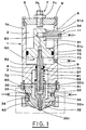
- reference numeral 1 indicates a hollow member, of substantially cylindrical section and open at its ends.
- the diameter of the lower chamber 3 is smaller than the diameter of the upper chamber 2.
- the member 1 is closed at the top by a cover 5 fastened thereto by screws 6.
- adjusting means 7 mounted in an axial through hole made in the said cover 5, and formed, preferably, by a screw 7a that is locked in a predetermined position by a lock nut, so that a predetermined adjustable part of the screw protrudes toward the upper chamber 2.
- the upper chamber 2 communicates with outside by means of a slot 8, made in one side of the hollow member close to its upper end, and by means of a threaded through hole 9, also made in the side of the hollow member but close to the said collar section 4.
- the hole 9 is aimed at allowing introduction of compressed air into the upper chamber 2.
- the hollow member 1 includes a main member 1a and a secondary member 30 that is basically cylindrical in its upper part 31, while its lower terminal part 32 has a diameter smaller than the diameter of the upper part 31 and is tapered.
- the secondary member 30 has a hollow 33, formed by three cylindrical sections of decreasing diameter, respectively an upper section 33a, an intermediate section 33b, and a lower section 33c.
- the lower section 33c is open to the outside by means of an exit orifice 84, while the upper section 33a is adjacent and coaxial with respect to the lower chamber 3 of the main member 1a, and has a diameter equal to the diameter thereof.
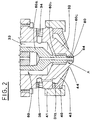
- the inferior part of the upper section 31 is externally threaded so that a screw cap 41 can be screwed thereonto to constrain a ring 40 that remains in abutment on the same upper section 31, so as to cover the terminal section 32.
- the ring 40 is tapered according to an angle bigger than the taper angle of the terminal section 32, so as to delimit a ring-like recess 43 therebetween, opening downwards by a ring-like orifice 44.
- This orifice is delimited by the lower edge of the ring 40 and by the surface of the terminal section 32 facing the ring 40.
- the clearance of the ring-like orifice is small enough to allow solvent to go out in such quantities that a thin layer thereof is formed on the lower surface of the terminal section 32, up to the exit orifice 84.
- the secondary member 30 has also glue supplying means 34 and solvent supplying means 35.
- the solvent supplying means 35 are connected at one side to a container of solvent under pressure, that is not shown, and at the other side to the ring-like recess 43, via a feeding duct 36.
- a movable member 50 Inside the main member 1a and the secondary member 30 there is located a movable member 50, aimed at directing and controlling the flows of glue and compressed air.
- the movable member 50 features a nozzle 60, with axially joined thereto, by means of threaded couplings, other two blocks, a first block 51 and a second block 57 respectively.
- the first block 51 is located inside the upper chamber 2 and includes two segments, upper 51a and lower 51b, respectively.
- the diameter of the lower segment 51b is bigger than the diameter of the upper segment 51a and equal to the diameter of the said upper chamber 2.
- a transverse blind hole 53 is made in the first bar 51 close to its upper end.
- connection member 54 is screwed to the transverse hole 53, by means of a threaded coupling, and goes out of the main member 1a through the slot 8, whose length is not smaller than the full displacement of the movable member 50.
- the second block 57 basically cylindrical, is slidably inserted inside the collar section 4 described before, is threaded at both its ends and, right over the lower threading, it features a flange 59.
- the nozzle 60 has three cylindrical portions of decreasing diameter respectively, upper 60a, intermediate 60b, and lower 60c, which fit to the shape of the hollow 33 of the secondary member 30 and are joined one to another by tapered sections.
- the lower portion 60c of the nozzle 60 is introduced in the lower section 33c of the hollow 33 and is similar in length thereto, so as to define a ring-like passage 80 that leads to the outside.
- the movable member 50 has also an axial hole 82, that includes a series of holes connected one to another and respectively made in the nozzle 60, in the second block 57 and in the first block 51, so that the lower end of the nozzle 60 can be set into communication with a controlled compressed air feeding device, that is not illustrated.
- the first tight means 70 include e.g. a first sealing ring, introduced in a respective first circular groove 52 made in the outer surface of the segment 51b of the first block 51.
- the second tight means 71 include, in similar way, a second sealing ring, introduced in a respective second circular groove made in the circular inner surface of the collar section 4.
- the first 70 and second 71 sealing rings provide tightness for a delimit an airtight chamber 73 whose volume can be varied, that is filled with compressed air.
- the airtight chamber 73 is connected, via the threaded hole 9, with a controlled compressed air feeding device that is not illustrated.
- the third sealing ring 72 is preferably formed by an ring-like elastic partition, whose outer edge is placed and locked between the main member 1a and the secondary member 30, while its inner edge is placed and locked between the second block 57 and the nozzle 60 of the movable member 50.
- the said ring-like elastic partition 72 forms the upper wall of the hollow 33, that is connected, via the glue supplying means 34, with a container of glue under pressure, not illustrated since known.
- the ring-like elastic partition 72 allows the movable member 50 to slide axially.
- elastic reaction means 81 including e.g. an helical spring, acting on the collar section 4 and the flange 59, so as to push downwards the movable member 50 until it reaches a closing position A, illustrated in Figure 2.
- the intermediate portion 60b of the nozzle 60 closes the connection between the ring-like passage 80 and the hollow 33, preventing the same glue from going out.
- the glue cannot reach the ring-like passage 80, since its opening is closed by the intermediate portion 60b of the nozzle 60 and therefore the glue remains closed in the hollow 33.
- the pressure in the chamber 73 increases and, subsequently, the movable member 50 is axially pushed upwards with a force bigger than the reaction of the helical spring 81, so that the spring is compressed and the movable member 50 slides until it reaches the opening position B, not illustrated, defined by the adjusting means 7, against which the upper end of the first block 51 strikes.
- the hollow 33 is again connected with the ring-like passage 80, through which glue can be spread out in an ring-like jet directed downwards.
- the compressed air goes out through the lower end of the nozzle 60, in coaxial relation with and in the middle of the glue stream, thus atomising the glue and distributing it in a circular area concentrical with the same nozzle 60.
- the said means 35 feeding the ring-like recess 43 with the solvent are activated.
- a thin layer of solvent goes out of the recess 43 through the ring-like opening 44 and comes, substantially by action of gravity, at the opening of the ring-like passage 80, thus preventing solidification of glue going out through the said opening 84.
- the reduction of pressure in the chamber 73 allows the helical spring 81 to displace the movable member 50 again to the closing position A and consequently, to stop the flow of glue toward the ring-like passage 80.
- the solvent is introduced only for a predetermined period of time, immediately after and/or before stopping the device.
- the present invention allows to apply glue, on industrial scale, in a uniform and constant way.
- the particular structure of the outlet orifices for glue and compressed air, together with constant flow of solvent towards the glue exit orifice permit to avoid any possibility of glue solidification and therefore any unhomogeneity of the distribution of the atomised stream of glue.
Landscapes
- Nozzles (AREA)
- Application Of Or Painting With Fluid Materials (AREA)
Applications Claiming Priority (2)
| Application Number | Priority Date | Filing Date | Title |
|---|---|---|---|
| IT94BO000208A ITBO940208A1 (it) | 1994-05-11 | 1994-05-11 | Pistola perfezionata per l'applicazione di collante |
| ITBO940208 | 1994-05-11 |
Publications (2)
| Publication Number | Publication Date |
|---|---|
| EP0682986A2 true EP0682986A2 (de) | 1995-11-22 |
| EP0682986A3 EP0682986A3 (de) | 1997-12-17 |
Family
ID=11339800
Family Applications (1)
| Application Number | Title | Priority Date | Filing Date |
|---|---|---|---|
| EP94830599A Withdrawn EP0682986A3 (de) | 1994-05-11 | 1994-12-30 | Sprühpistole zum Klebstoffauftrag |
Country Status (3)
| Country | Link |
|---|---|
| EP (1) | EP0682986A3 (de) |
| BR (1) | BR9405313A (de) |
| IT (1) | ITBO940208A1 (de) |
Cited By (2)
| Publication number | Priority date | Publication date | Assignee | Title |
|---|---|---|---|---|
| CN106391405A (zh) * | 2016-11-29 | 2017-02-15 | 哈尔滨哈电汽发电站设备有限责任公司 | 一种适用于发电机组的液压注胶枪 |
| CN109261449A (zh) * | 2018-11-19 | 2019-01-25 | 大连金杰创新科技有限公司 | 一种循环清洗单组份涂胶头 |
Families Citing this family (1)
| Publication number | Priority date | Publication date | Assignee | Title |
|---|---|---|---|---|
| CN114834094B (zh) * | 2022-05-28 | 2023-09-15 | 厦门金锐奇工贸有限公司 | 一种用于纸袋糊底机的上胶翻底机构 |
Family Cites Families (3)
| Publication number | Priority date | Publication date | Assignee | Title |
|---|---|---|---|---|
| DE2946217A1 (de) * | 1979-11-15 | 1981-05-21 | DeVilbiss Europa GmbH, 6078 Neu Isenburg | Spritzpistole |
| DE8227445U1 (de) * | 1982-09-30 | 1983-01-05 | Beckersjürgen, Robert, 4402 Greven | Dueseneinheit, mit zwei hintereinander liegenden abrisskanten |
| CA1336373C (en) * | 1988-09-21 | 1995-07-25 | Nordson Corporation | Apparatus for spraying hot melt adhesives |
-
1994
- 1994-05-11 IT IT94BO000208A patent/ITBO940208A1/it unknown
- 1994-12-29 BR BR9405313A patent/BR9405313A/pt not_active IP Right Cessation
- 1994-12-30 EP EP94830599A patent/EP0682986A3/de not_active Withdrawn
Cited By (2)
| Publication number | Priority date | Publication date | Assignee | Title |
|---|---|---|---|---|
| CN106391405A (zh) * | 2016-11-29 | 2017-02-15 | 哈尔滨哈电汽发电站设备有限责任公司 | 一种适用于发电机组的液压注胶枪 |
| CN109261449A (zh) * | 2018-11-19 | 2019-01-25 | 大连金杰创新科技有限公司 | 一种循环清洗单组份涂胶头 |
Also Published As
| Publication number | Publication date |
|---|---|
| EP0682986A3 (de) | 1997-12-17 |
| BR9405313A (pt) | 1995-12-05 |
| ITBO940208A0 (it) | 1994-05-11 |
| ITBO940208A1 (it) | 1995-11-11 |
Similar Documents
| Publication | Publication Date | Title |
|---|---|---|
| KR102476413B1 (ko) | 접착제 분배 모듈 및 액체 접착제의 복수의 액적의 분무 방법 | |
| US5419491A (en) | Two component fluid spray gun and method | |
| EP0389657A1 (de) | Einstellbare Flüssigkeitssprühpistole mit einer Luftübergangsdüse | |
| EP0528559B1 (de) | Zerstäuber | |
| US5730326A (en) | Rechargeable aerosol can and spray valve with integral mixing device for propellant and substance to be sprayed | |
| US5323935A (en) | Consumer product package incorporating a spray device utilizing large diameter bubbles | |
| US8083159B2 (en) | Push-button nozzle for liquid product dispenser | |
| CA1056781A (en) | Squeeze bottle containing a liquid product and operative whether upright or inverted | |
| US6050504A (en) | Spray dispensing device using swirl passages and using the Bernoulli effect | |
| RU2121885C1 (ru) | Комбинированная дозирующая и распылительная насадка | |
| EP1301404B1 (de) | Quetschbehälter mit regelbarer abgabevorrichtung | |
| PL164229B1 (pl) | Zespól nastawny dyszy dozownika cieczy PL PL PL PL | |
| US5270013A (en) | Reactive fluid mixing head | |
| US12533691B2 (en) | Pneumatic material spray gun | |
| US20110210184A1 (en) | Device for mixing media and method for producing same ("aeroflair spray nozzle") | |
| JPH07185397A (ja) | 遮断時滴下防止機能を伴う液体ディスペンサ | |
| AU2001275464A1 (en) | Variable discharge dispensing head for a squeeze dispenser | |
| KR20190051874A (ko) | 사전-분무화 협폭부를 구비한 스프레이 노즐, 상기 스프레이 노즐을 포함하는 스프레이 헤드 및 스프레이 장치 | |
| US4401270A (en) | Sprayer for squeeze bottle | |
| PL201410B1 (pl) | Ręcznie uruchamiany rozpylacz | |
| EP0682986A2 (de) | Sprühpistole zum Klebstoffauftrag | |
| US5586723A (en) | Liquid spray nozzle with liquid injector/extractor | |
| KR100517798B1 (ko) | 유체혼합용 분사노즐 | |
| JPH03114559A (ja) | スプレーガン | |
| KR200331603Y1 (ko) | 유체혼합용 분사노즐 |
Legal Events
| Date | Code | Title | Description |
|---|---|---|---|
| PUAI | Public reference made under article 153(3) epc to a published international application that has entered the european phase |
Free format text: ORIGINAL CODE: 0009012 |
|
| AK | Designated contracting states |
Kind code of ref document: A2 Designated state(s): DE ES FR GB PT |
|
| PUAL | Search report despatched |
Free format text: ORIGINAL CODE: 0009013 |
|
| AK | Designated contracting states |
Kind code of ref document: A3 Designated state(s): DE ES FR GB PT |
|
| 17P | Request for examination filed |
Effective date: 19980505 |
|
| GRAG | Despatch of communication of intention to grant |
Free format text: ORIGINAL CODE: EPIDOS AGRA |
|
| GRAG | Despatch of communication of intention to grant |
Free format text: ORIGINAL CODE: EPIDOS AGRA |
|
| GRAH | Despatch of communication of intention to grant a patent |
Free format text: ORIGINAL CODE: EPIDOS IGRA |
|
| GRAH | Despatch of communication of intention to grant a patent |
Free format text: ORIGINAL CODE: EPIDOS IGRA |
|
| 17Q | First examination report despatched |
Effective date: 19990331 |
|
| STAA | Information on the status of an ep patent application or granted ep patent |
Free format text: STATUS: THE APPLICATION IS DEEMED TO BE WITHDRAWN |
|
| 18D | Application deemed to be withdrawn |
Effective date: 19990810 |