EP0683043B1 - Cylindre d'impression d'une machine d'impression rotative - Google Patents
Cylindre d'impression d'une machine d'impression rotative Download PDFInfo
- Publication number
- EP0683043B1 EP0683043B1 EP95106293A EP95106293A EP0683043B1 EP 0683043 B1 EP0683043 B1 EP 0683043B1 EP 95106293 A EP95106293 A EP 95106293A EP 95106293 A EP95106293 A EP 95106293A EP 0683043 B1 EP0683043 B1 EP 0683043B1
- Authority
- EP
- European Patent Office
- Prior art keywords
- printing unit
- unit cylinder
- journal
- ring
- mounting
- Prior art date
- Legal status (The legal status is an assumption and is not a legal conclusion. Google has not performed a legal analysis and makes no representation as to the accuracy of the status listed.)
- Expired - Lifetime
Links
- 230000008878 coupling Effects 0.000 claims description 15
- 238000010168 coupling process Methods 0.000 claims description 15
- 238000005859 coupling reaction Methods 0.000 claims description 15
- 238000005096 rolling process Methods 0.000 description 4
- 238000006073 displacement reaction Methods 0.000 description 3
- 230000006835 compression Effects 0.000 description 2
- 238000007906 compression Methods 0.000 description 2
- 210000000078 claw Anatomy 0.000 description 1
- 239000000725 suspension Substances 0.000 description 1
Images


Classifications
-
- B—PERFORMING OPERATIONS; TRANSPORTING
- B41—PRINTING; LINING MACHINES; TYPEWRITERS; STAMPS
- B41F—PRINTING MACHINES OR PRESSES
- B41F13/00—Common details of rotary presses or machines
- B41F13/08—Cylinders
- B41F13/24—Cylinder-tripping devices; Cylinder-impression adjustments
- B41F13/26—Arrangement of cylinder bearings
- B41F13/28—Bearings mounted eccentrically of the cylinder axis
Definitions
- the invention relates to a printing unit cylinder Web-fed rotary printing press according to the preamble of claim 1 and 7.
- the invention relates to forme cylinders and Transfer cylinder.
- the invention has for its object to printing cylinder create with which a good print quality can be achieved.
- the printing unit cylinders are backlash-free or low-backlash can be stored in or on the side walls of the printing unit. You point also none to be rotated or pushed in the side wall Cans on. These bushes can therefore be used in the wall without play mounted or even clamped in the wall. Overall is good print quality can thereby be achieved.
- d. H. when the storage of the Printing unit cylinder, the eccentric not its rotational position, d. H. of the Printing unit cylinder remains unchanged when changing sleeves Position at.
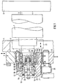
- Fig. 1 is a transfer cylinder 1 as a printing unit cylinder shown, the with its pin 2, 3 in side walls 4, 5 one Printing unit is stored.
- the storage in the side wall 5 is there not part of the subject of the invention, not described in detail.
- the pin 2 is mounted indirectly in the side wall 4.
- the Side wall 4 has an opening 6 in the region of the pin 2, which with arranged on the side wall 4, transversely to the pin 2 Slidable slider 7, 8 is closed or exposed.
- a Execution of such slide is for example in the EP 0 277 545 B1.
- a guide 9 for the slide is indicated.
- the slider 7, 8 take in the drawn closed state Storage 10 of the pin 2 on.
- the latter contains three interlocking rings 11, 12, 13 which are mutually supported themselves are.
- the inner ring 11 is arranged on the pin 2 and by means of a two-row cylindrical roller bearing 14 stored in the ring 12.
- the latter is in turn by means of a double row needle bearing 15 in Ring 13 stored.
- a double row needle bearing 15 in Ring 13 stored For storing the rings 11, 12, 13 one inside the other can also use other roller bearings or plain bearings Are used, however, rolling bearings are quite suitable Realization of a desired play-free storage.
- the ring 12 is eccentrically trained and can rotate it for the Printing on and off of the transfer cylinder 1 whose axis move.
- the ring 12 has an outer jacket eccentric bore 16 in which the cylindrical roller bearing 14 is recorded. But it is still advantageous between that Cylindrical roller bearing 14 and the ring 12 an eccentric ring 17th set, which serves the basic setting of the transfer cylinder 1.
- the ring 17 is press-fit in the bore 16 stored.
- the press fit with a Hydraulic press fit not shown, canceled.
- the Adjustment itself can be done, for example, by a person skilled in the art common threaded spindle drive.
- the ring 17 can also Rolling in the ring 12 may be arranged.
- the ring 12 is designed as a sleeve 18.
- a rod 19 attached, which in turn rotatably mounted on the pin 2 is.
- it carries two deep groove ball bearings 20, 21 at its end. which are received in a bore of the pin 2.
- the Deep groove ball bearings 20, 21 can also be used other bearings that can absorb an axial force.
- the box 18 is furthermore the first coupling half 22 of a clutch 23 housed.
- the coupling half 22 is against the force of springs, for example, disc springs 24, which are at the bottom of the sleeve 18th support, movable. It is still with a parallel key 25 secured against twisting.
- the first coupling half 22 works with a second attached to the end face of the pin 2 Coupling half 26 together. She wears on her outer jacket Coupling half 22 a circumferential groove 27 into which one in the sleeve 18th stored shift fork 28 engages with sliding blocks 29. At the Shift fork 28 is also a lever 30 which is arranged by the Slider 7 is actuated.
- the Clutch could also be used as a claw or Tooth coupling are carried out.
- the engaged clutch 23 causes the eccentrically formed ring 12 when changing the blanket sleeve 31, d. H. with exposed storage 10 not can twist relative to the transfer cylinder 1.
- the latter in turn is secured against rotation by the drive with which the pin 3, not shown, is connected. Still does not shown, on the pin 3 to a device that the Transfer cylinder 1 flying with exposed storage 10 held in suspension.
- One now over the exposed Pin 2 changeable rubber blanket sleeve 31 is dash-dotted shown. After the sleeve has been changed, the slides 7, 8 moved back to the drawn position.
- the changes Transfer cylinder thanks to the unchanged position of the eccentric trained ring 12 its location.
- an actuator 32 for the ring 12 in the latter can also be used for Closing the slide 8 an actuator 32 for the ring 12 in the latter are engaged.
- the adjustment of the ring 12 serves as already explained above, the printing on and off.
- Actuator 32 comes in the embodiment accordingly actuated pinion 33 for use, which in a toothed segment 34 of the Bush engages 18.
- the rod 19 also secures the sleeve 18 against Move.
- Driving plate 35 is provided, which in a groove 36 of the ring 12th intervenes.
- the backup could also be done in another way, for example, in that the needle bearing 15 with axial fixing is executed.
- a forme cylinder 37 is shown in FIG. the one with its pin 38, 39 in side walls 40, 41 Printing unit is stored.
- the bearing 42 of the pin 38 of Sliders 43, 44 added, which are slidable on the side wall 40 are arranged and in the position shown an opening 62 of the Close side wall 40.
- the bearing 42 contains two one inside the other lying, axially displaceable rings 45, 46.
- the rings 45, 46 are in the embodiment of a double row Cylindrical roller bearings 47 embodied. But could also be used other rolling bearings without axial fixation, e.g. B. needle bearings, or come with slide bearing rings. It is an advantage at Rolling bearings whose good possibility of adjusting to freedom from play.
- the ring 46 is fixed in a sleeve 48 arranged.
- the center of the jacket Bush 48 arranged a bore through which a Rod 49 is passed.
- Both sides of the bottom hole of the Bushing 18 are on the rod 49 compression springs 50, 51 which against the bottom of the sleeve 48 and stops 52, 53 of the rod Support 49.
- the rod also carries two deep groove ball bearings 54, 55, which are received in a bore of the pin 38.
- the conditions for the deep groove ball bearings 54, 55 are the same, like that of the deep groove ball bearing 20, 21 in FIG. 1.
- FIG. 2 (claim 7) is also, for example applicable to the printing unit cylinder according to FIG. 1. So it can Bushing 18 'may be provided with stops 57, 58, against which Support compression springs 59, 60, between which in turn the ring 13 ' is placed (Fig. 3).
- Stop 57, 58 against which Support compression springs 59, 60, between which in turn the ring 13 ' is placed (Fig. 3).
- the outer ring can also be indirect, e.g. B. over an adjacent Ring to be put into a zero position for example in that the outer ring without Freedom of sliding is mounted on the adjacent ring. On the latter ring then attacks the device for zeroing.
Landscapes
- Engineering & Computer Science (AREA)
- Mechanical Engineering (AREA)
- Rotary Presses (AREA)
Claims (9)
- Cylindre (1) d'une unité d'impression d'une presse rotative à imprimer, qui est tourillonné, par ses tourillons (2), au moins indirectement dans ou sur deux parois latérales et sur lequel une douille peut être emmanchée ou à partir duquel une douille peut être retirée par une ouverture formée dans une paroi latérale une fois que le support au niveau du tourillon (2) situé du côté de l'ouverture est libéré, caractérisé en ce que le support (10) contient plusieurs bagues (11,12,13) situées les unes dans les autres et dont l'une au moins (12) est disposée d'une manière excentrique, de telle sorte que, dans l'état de fonctionnement, lors de sa rotation elle peut déplacer l'axe du cylindre (1) de l'unité d'impression et, pendant le changement de la douille, ladite bague (12) est bloquée contre toute rotation, notamment par le fait qu'elle est reliée au tourillon (2).
- Cylindre d'une unité d'impression selon la revendication 1, caractérisé en ce que le support contient plusieurs bagues (11,12,13) situées les unes dans les autres et supportées les unes par rapport aux autres par un roulement et dont au moins l'une d'elles (12) est réalisée en étant excentrique de telle sorte que dans l'état de fonctionnement, lors de sa rotation elle peut translater l'axe du cylindre (1) de l'unité d'impression, et qu'il est prévu un dispositif qui, pendant le changement de la douille, bloque ladite plaque (12) contre une rotation par rapport au tourillon (2).
- Cylindre d'une unité d'impression selon la revendication 1 ou 2, caractérisé en ce qu'il est prévu un dispositif, qui bloque la bague excentrique (12) contre un déplacement par rapport au tourillon (2).
- Cylindre d'une unité d'impression selon l'une des revendications précédentes, caractérisé en ce qu'une autre bague excentrée (17) est disposée dans la bague excentrique (12), de manière à être réglable dans la direction circonférentielle.
- Cylindre d'une unité d'impression selon la revendication 4, caractérisé en ce que l'autre bague excentrique (17) est disposée, en étant supportée par un roulement dans la bague (12).
- Cylindre d'une unité d'impression selon l'une des revendications précédentes, caractérisé en ce que la bague excentrique (12) est agencée sous la forme d'un manchon (18), auquel est fixée une tige (19), qui est montée de manière à pouvoir tourner sur le tourillon (2) du cylindre (1) de l'unité d'impression, de sorte que le manchon (18) supporte en outre la première moitié (22) d'un embrayage (23), dont la seconde moitié (26) est fixée à la face frontale du tourillon (2), que la première moitié (22) de l'embrayage est montée sans possibilité de rotation et avec possibilité de translation dans le manchon (18) et prend appui moyennant un montage intercalé de ressorts sur le fond du manchon (18), que la première moitié (22) de l'embrayage porte une gorge circonférentielle (27), dans laquelle s'engage une fourche de commutation (28) tourillonnée dans le manchon (18) et qui est actionnée par la paroi latérale (4) de telle sorte qu'elle accouple l'embrayage (23) lors de la libération du support (10).
- Cylindre (1) d'une unité d'impression d'une presse rotative à imprimer, qui est tourillonné, par ses tourillons (2), au moins indirectement dans ou sur deux parois latérales, et sur lequel une douille peut être emmanchée ou à partir duquel une douille peut être retirée par une ouverture formée dans une paroi latérale une fois que le support au niveau du tourillon (2) situé du côté de l'ouverture est libéré, caractérisé en ce que le support (42) contient plusieurs bagues (45,46) situées les unes dans les autres et dont au moins deux bagues (45,46) peuvent être translatées axialement l'une par rapport à l'autre et qu'il est prévu un dispositif, qui pendant le changement de la douille, règle la bague extérieure (46) dans une position nulle par rapport au tourillon (38) et/ou la retient dans ce tourillon.
- Cylindre d'une unité d'impression selon la revendication 7, caractérisé en ce que les bagues (45,46) sont supportées l'une par rapport à l'autre par un roulement.
- Cylindre d'une unité d'impression selon la revendication 7 ou 8, caractérisé en ce que la bague extérieure (46) est montée dans un manchon (48), dans le fond duquel est enfichée une tige (49), qui peut être déplacée dans sa direction longitudinale à l'encontre de la force de ressorts (50,51) et qui est montée de manière à pouvoir tourner sur le tourillon (38) du cylindre (37) de l'unité d'impression.
Applications Claiming Priority (2)
| Application Number | Priority Date | Filing Date | Title |
|---|---|---|---|
| DE4415340 | 1994-05-02 | ||
| DE4415340A DE4415340C2 (de) | 1994-05-02 | 1994-05-02 | Druckwerkszylinder einer Rollenrotationsdruckmaschine |
Publications (2)
| Publication Number | Publication Date |
|---|---|
| EP0683043A1 EP0683043A1 (fr) | 1995-11-22 |
| EP0683043B1 true EP0683043B1 (fr) | 1998-05-20 |
Family
ID=6517016
Family Applications (1)
| Application Number | Title | Priority Date | Filing Date |
|---|---|---|---|
| EP95106293A Expired - Lifetime EP0683043B1 (fr) | 1994-05-02 | 1995-04-27 | Cylindre d'impression d'une machine d'impression rotative |
Country Status (5)
| Country | Link |
|---|---|
| US (2) | US5505127A (fr) |
| EP (1) | EP0683043B1 (fr) |
| JP (1) | JP2746546B2 (fr) |
| CA (1) | CA2148389C (fr) |
| DE (2) | DE4415340C2 (fr) |
Cited By (5)
| Publication number | Priority date | Publication date | Assignee | Title |
|---|---|---|---|---|
| US7516698B2 (en) | 2005-03-30 | 2009-04-14 | Goss International Americasn, Inc. | Web offset printing press with autoplating |
| US7775159B2 (en) | 2005-03-30 | 2010-08-17 | Goss International Americas, Inc. | Cantilevered blanket cylinder lifting mechanism |
| US7819057B2 (en) | 2005-03-30 | 2010-10-26 | Goss International Americas, Inc. | Print unit having blanket cylinder throw-off bearer surfaces |
| US7849796B2 (en) | 2005-03-30 | 2010-12-14 | Goss International Americas, Inc | Web offset printing press with articulated tucker |
| US8037818B2 (en) | 2005-04-11 | 2011-10-18 | Goss International Americas, Inc. | Print unit with single motor drive permitting autoplating |
Families Citing this family (6)
| Publication number | Priority date | Publication date | Assignee | Title |
|---|---|---|---|---|
| DE59504993D1 (de) * | 1995-10-18 | 1999-03-11 | Fischer & Krecke Gmbh & Co | Vorrichtung zum Wechseln von Druckzylinderhülsen in Druckmaschinen |
| DE19627034C2 (de) * | 1996-07-05 | 2002-12-05 | Armin Steuer | Einrichtung zum Betrieb eines Klischee-Zylinders |
| US5943955A (en) | 1997-08-29 | 1999-08-31 | Goss Graphic Systems, Inc. | Printing press having cantilevered self-driven cylinders |
| DE19961190B4 (de) * | 1999-12-18 | 2004-03-11 | Man Roland Druckmaschinen Ag | Selbst ein- und nachstellende Lagerung für Walzen eines Farb- oder Feuchtwerkes einer Druckmaschine |
| JP2002046251A (ja) * | 2000-06-26 | 2002-02-12 | Heidelberger Druckmas Ag | 偏心箱を使用して胴の胴抜きを行うための機構 |
| CN112706505B (zh) * | 2021-02-19 | 2024-05-03 | 温州海多堡机械科技有限公司 | 一种直驱式版辊结构 |
Family Cites Families (15)
| Publication number | Priority date | Publication date | Assignee | Title |
|---|---|---|---|---|
| DE290853C (fr) * | ||||
| DE2614792A1 (de) * | 1976-04-06 | 1977-10-27 | Maschf Augsburg Nuernberg Ag | Rotationsdruckmaschine |
| CS228675B1 (en) * | 1982-04-01 | 1984-05-14 | Jaroslav Jiruse | Apparatus for controlling printing rollers |
| DE3324811A1 (de) * | 1983-07-09 | 1985-01-17 | INA Wälzlager Schaeffler KG, 8522 Herzogenaurach | Waelzlagerung fuer die zapfen von gummizylindern in druckmaschinen |
| DE3702889A1 (de) * | 1987-01-31 | 1988-08-11 | Roland Man Druckmasch | Vorrichtung zum aufbringen einer huelse auf einen druckwerkzylinder |
| DE3705477C1 (de) * | 1987-02-20 | 1988-05-26 | Roland Man Druckmasch | Haltevorrichtung fuer das Aufbringen einer Huelse auf einen Zylinder |
| DE3715536A1 (de) * | 1987-05-09 | 1988-12-01 | Roland Man Druckmasch | Lagerung fuer einen druckwerkzylinder |
| DE3805143C1 (fr) * | 1988-02-19 | 1989-03-23 | Man Roland Druckmaschinen Ag, 6050 Offenbach, De | |
| IT1230954B (it) * | 1989-06-30 | 1991-11-08 | Cerutti Spa Off Mec | Gruppo di stampa con forma stampante a sostituzione rapida. |
| DE9115471U1 (de) * | 1991-10-19 | 1992-02-20 | Koenig & Bauer AG, 8700 Würzburg | Anordnung zum Einstellen des Lagerspiels bei Zylindern von Druckmaschinen |
| US5289769A (en) * | 1992-08-17 | 1994-03-01 | W. O. Hickok Mfg., Co. | Method and apparatus for changing a printing sleeve |
| US5241905A (en) * | 1992-10-27 | 1993-09-07 | Heidelberg Harris Inc. | Printing unit with releasable bearing clamp |
| DE4241567A1 (de) * | 1992-12-10 | 1994-06-16 | Roland Man Druckmasch | Vorrichtung zur Druckeinstellung eines mit einer aufschiebbaren Hülse ausgestatteten Druckzylinders |
| DE4241565A1 (de) * | 1992-12-10 | 1994-06-16 | Roland Man Druckmasch | Lagerung für einen mit einer aufschiebbaren Hülse ausgestatteten Druckzylinder |
| DE4302149A1 (de) * | 1993-01-27 | 1994-07-28 | Heidelberger Druckmasch Ag | Vorrichtung zum Einstellen des Seiten- und Schrägregisters am Plattenzylinder von Rotationsdruckmaschinen |
-
1994
- 1994-05-02 DE DE4415340A patent/DE4415340C2/de not_active Expired - Fee Related
-
1995
- 1995-04-18 JP JP7092872A patent/JP2746546B2/ja not_active Expired - Fee Related
- 1995-04-27 DE DE59502221T patent/DE59502221D1/de not_active Expired - Lifetime
- 1995-04-27 US US08/429,814 patent/US5505127A/en not_active Expired - Lifetime
- 1995-04-27 EP EP95106293A patent/EP0683043B1/fr not_active Expired - Lifetime
- 1995-05-02 CA CA002148389A patent/CA2148389C/fr not_active Expired - Fee Related
- 1995-10-20 US US08/546,353 patent/US5560292A/en not_active Expired - Lifetime
Cited By (6)
| Publication number | Priority date | Publication date | Assignee | Title |
|---|---|---|---|---|
| US7516698B2 (en) | 2005-03-30 | 2009-04-14 | Goss International Americasn, Inc. | Web offset printing press with autoplating |
| US7775159B2 (en) | 2005-03-30 | 2010-08-17 | Goss International Americas, Inc. | Cantilevered blanket cylinder lifting mechanism |
| US7819057B2 (en) | 2005-03-30 | 2010-10-26 | Goss International Americas, Inc. | Print unit having blanket cylinder throw-off bearer surfaces |
| US7849796B2 (en) | 2005-03-30 | 2010-12-14 | Goss International Americas, Inc | Web offset printing press with articulated tucker |
| US8250976B2 (en) | 2005-03-30 | 2012-08-28 | Goss International Americas, Inc. | Cantilevered blanket cylinder lifting mechanism |
| US8037818B2 (en) | 2005-04-11 | 2011-10-18 | Goss International Americas, Inc. | Print unit with single motor drive permitting autoplating |
Also Published As
| Publication number | Publication date |
|---|---|
| US5505127A (en) | 1996-04-09 |
| DE4415340C2 (de) | 1996-03-14 |
| EP0683043A1 (fr) | 1995-11-22 |
| JP2746546B2 (ja) | 1998-05-06 |
| CA2148389A1 (fr) | 1995-11-03 |
| CA2148389C (fr) | 1998-11-03 |
| JPH07299896A (ja) | 1995-11-14 |
| DE59502221D1 (de) | 1998-06-25 |
| DE4415340A1 (de) | 1995-11-16 |
| US5560292A (en) | 1996-10-01 |
Similar Documents
| Publication | Publication Date | Title |
|---|---|---|
| EP0782920B1 (fr) | Contrepoids et mécanisme de levage | |
| CH694759A5 (de) | Druckwerk. | |
| EP0769373B1 (fr) | Dispositif de changement des manchons de cylindres d'imprimerie dans les machines à imprimer | |
| EP0683043B1 (fr) | Cylindre d'impression d'une machine d'impression rotative | |
| EP0858887B1 (fr) | Machine à imprimer | |
| DE102008046792A1 (de) | Druckmaschine mit Schmitzringen | |
| DE4012965C1 (de) | Vorrichtung zum An-, Ab- und Einstellen von Auftragwalzen | |
| DE3126561C2 (de) | Lagerung für Druckwerkszylinder oder dergleichen mit einstellbarem Seitenregister | |
| EP1923214A2 (fr) | Unité d'impression d'une presse dotée de deux doubles groupes d'impressions agencés l'un sur l'autre | |
| DE1236529B (de) | Vorrichtung zur Lagerung sowie zum An- und Abstellen des mittleren Zylinders eines Dreizylinderdruckwerks | |
| EP0713023B1 (fr) | Accouplement d'arbres | |
| EP0771648B1 (fr) | Dispositif de rattrapage de jeu dans une machine d'impression | |
| EP2057017B1 (fr) | Élément d'impression d'une machine d'héliogravure | |
| DE10044860A1 (de) | Antriebsvorrichtung für Druckmaschinen | |
| EP1984181B1 (fr) | Couplage de cylindre gravé | |
| DE10014040B4 (de) | Welle zum Synchronisieren einer Stellbewegung | |
| DE10242009B4 (de) | Druckmaschine, vorzugsweise Flexodruckmaschine | |
| EP1016520B1 (fr) | Accouplement d'entraínement pour cylindre d'impression | |
| EP0847854B1 (fr) | Cylindre d'accumulation ou de pliage avec un disque de virage coulissant | |
| EP1923213B1 (fr) | Unité d'impression d'une presse dotée de deux doubles groupes d'impression agencés l'un sur l'autre | |
| DE10046375B4 (de) | Antrieb einer Druckeinheit | |
| DE10066156B4 (de) | Welle zum Synchronisieren einer Stellbewegung | |
| DE3304878A1 (de) | Vorrichtung zum drehen von durch schraubenfoermige federn belasteten ventilen in brennkraftmaschinen | |
| DE1636309C (de) | Lagerung des Druckzylinders einer Vervielfältigungsmaschine | |
| DE3112995A1 (de) | Druckwerk fuer eine kleinoffsetdruckmaschine |
Legal Events
| Date | Code | Title | Description |
|---|---|---|---|
| PUAI | Public reference made under article 153(3) epc to a published international application that has entered the european phase |
Free format text: ORIGINAL CODE: 0009012 |
|
| AK | Designated contracting states |
Kind code of ref document: A1 Designated state(s): CH DE FR GB IT LI SE |
|
| 17P | Request for examination filed |
Effective date: 19960329 |
|
| GRAG | Despatch of communication of intention to grant |
Free format text: ORIGINAL CODE: EPIDOS AGRA |
|
| 17Q | First examination report despatched |
Effective date: 19970630 |
|
| GRAG | Despatch of communication of intention to grant |
Free format text: ORIGINAL CODE: EPIDOS AGRA |
|
| GRAH | Despatch of communication of intention to grant a patent |
Free format text: ORIGINAL CODE: EPIDOS IGRA |
|
| GRAH | Despatch of communication of intention to grant a patent |
Free format text: ORIGINAL CODE: EPIDOS IGRA |
|
| ITF | It: translation for a ep patent filed | ||
| GRAA | (expected) grant |
Free format text: ORIGINAL CODE: 0009210 |
|
| AK | Designated contracting states |
Kind code of ref document: B1 Designated state(s): CH DE FR GB IT LI SE |
|
| REG | Reference to a national code |
Ref country code: CH Ref legal event code: NV Representative=s name: E. BLUM & CO. PATENTANWAELTE Ref country code: CH Ref legal event code: EP |
|
| REF | Corresponds to: |
Ref document number: 59502221 Country of ref document: DE Date of ref document: 19980625 |
|
| GBT | Gb: translation of ep patent filed (gb section 77(6)(a)/1977) |
Effective date: 19980818 |
|
| ET | Fr: translation filed | ||
| PGFP | Annual fee paid to national office [announced via postgrant information from national office to epo] |
Ref country code: FR Payment date: 19990324 Year of fee payment: 5 |
|
| PGFP | Annual fee paid to national office [announced via postgrant information from national office to epo] |
Ref country code: CH Payment date: 19990326 Year of fee payment: 5 |
|
| PLBE | No opposition filed within time limit |
Free format text: ORIGINAL CODE: 0009261 |
|
| STAA | Information on the status of an ep patent application or granted ep patent |
Free format text: STATUS: NO OPPOSITION FILED WITHIN TIME LIMIT |
|
| 26N | No opposition filed | ||
| PGFP | Annual fee paid to national office [announced via postgrant information from national office to epo] |
Ref country code: GB Payment date: 20000313 Year of fee payment: 6 |
|
| PGFP | Annual fee paid to national office [announced via postgrant information from national office to epo] |
Ref country code: SE Payment date: 20000320 Year of fee payment: 6 |
|
| PG25 | Lapsed in a contracting state [announced via postgrant information from national office to epo] |
Ref country code: LI Free format text: LAPSE BECAUSE OF NON-PAYMENT OF DUE FEES Effective date: 20000430 Ref country code: CH Free format text: LAPSE BECAUSE OF NON-PAYMENT OF DUE FEES Effective date: 20000430 |
|
| REG | Reference to a national code |
Ref country code: CH Ref legal event code: PL |
|
| PG25 | Lapsed in a contracting state [announced via postgrant information from national office to epo] |
Ref country code: FR Free format text: LAPSE BECAUSE OF NON-PAYMENT OF DUE FEES Effective date: 20001229 |
|
| REG | Reference to a national code |
Ref country code: FR Ref legal event code: ST |
|
| PG25 | Lapsed in a contracting state [announced via postgrant information from national office to epo] |
Ref country code: GB Free format text: LAPSE BECAUSE OF NON-PAYMENT OF DUE FEES Effective date: 20010427 |
|
| PG25 | Lapsed in a contracting state [announced via postgrant information from national office to epo] |
Ref country code: SE Free format text: LAPSE BECAUSE OF NON-PAYMENT OF DUE FEES Effective date: 20010428 |
|
| EUG | Se: european patent has lapsed |
Ref document number: 95106293.4 |
|
| GBPC | Gb: european patent ceased through non-payment of renewal fee |
Effective date: 20010427 |
|
| PG25 | Lapsed in a contracting state [announced via postgrant information from national office to epo] |
Ref country code: IT Free format text: LAPSE BECAUSE OF NON-PAYMENT OF DUE FEES Effective date: 20050427 |
|
| PGFP | Annual fee paid to national office [announced via postgrant information from national office to epo] |
Ref country code: DE Payment date: 20120629 Year of fee payment: 18 |
|
| REG | Reference to a national code |
Ref country code: DE Ref legal event code: R081 Ref document number: 59502221 Country of ref document: DE Owner name: MANROLAND WEB SYSTEMS GMBH, DE Free format text: FORMER OWNER: MANROLAND AG, 63075 OFFENBACH, DE Effective date: 20120626 |
|
| PG25 | Lapsed in a contracting state [announced via postgrant information from national office to epo] |
Ref country code: DE Free format text: LAPSE BECAUSE OF NON-PAYMENT OF DUE FEES Effective date: 20131101 |
|
| REG | Reference to a national code |
Ref country code: DE Ref legal event code: R119 Ref document number: 59502221 Country of ref document: DE Effective date: 20131101 |