EP0683073A1 - Séparation de protection de l'espace en arrière du siège avant ou arrière d'un véhicule - Google Patents
Séparation de protection de l'espace en arrière du siège avant ou arrière d'un véhicule Download PDFInfo
- Publication number
- EP0683073A1 EP0683073A1 EP95106624A EP95106624A EP0683073A1 EP 0683073 A1 EP0683073 A1 EP 0683073A1 EP 95106624 A EP95106624 A EP 95106624A EP 95106624 A EP95106624 A EP 95106624A EP 0683073 A1 EP0683073 A1 EP 0683073A1
- Authority
- EP
- European Patent Office
- Prior art keywords
- frame section
- backrest
- section
- upper frame
- sections
- Prior art date
- Legal status (The legal status is an assumption and is not a legal conclusion. Google has not performed a legal analysis and makes no representation as to the accuracy of the status listed.)
- Granted
Links
Images


Classifications
-
- B—PERFORMING OPERATIONS; TRANSPORTING
- B60—VEHICLES IN GENERAL
- B60R—VEHICLES, VEHICLE FITTINGS, OR VEHICLE PARTS, NOT OTHERWISE PROVIDED FOR
- B60R21/00—Arrangements or fittings on vehicles for protecting or preventing injuries to occupants or pedestrians in case of accidents or other traffic risks
- B60R21/02—Occupant safety arrangements or fittings, e.g. crash pads
- B60R21/026—Rigid partitions inside vehicles, e.g. between passengers and load compartments
Definitions
- the invention relates to a device for the protective separation of the space behind the front or rear seat of a passenger car according to the preamble of claim 1.
- the invention has for its object to provide a device for the protective separation of the space behind the front or rear seats of a passenger car, which can be permanently installed and still be put into and out of operation. Furthermore, it should be usable with the backrest of the rear seats raised as well as with the backrest folded forward.
- the device according to the invention provides a protective frame made of rigid material, preferably hollow rod material is made.
- a lower frame section can be suitably releasably attached to the back of the back of the rear seat. It remains in the fixed position when the backrest is folded up.
- the upper frame section can, however, between a lower position in which it is largely covered by the backrest and an upper position in which the upper frame section abuts the ceiling of the body or ends at a short distance from it.
- the upper frame section is fastened in a suitable manner to the ceiling and / or to the pillar of the body, for example by means of a screw or snap fastening.
- the upper frame section is guided telescopically on the lower one, whereby tubular hollow profiles expediently cooperate in order to be able to carry out the adjustment in a simple manner.
- tubular hollow profiles expediently cooperate in order to be able to carry out the adjustment in a simple manner.
- the back of the rear seats is often divided.
- an embodiment of the invention provides that a separate protective frame is assigned to each backrest section.
- the upper frame section can be connected to the roof or laterally to the pillar of the body by means of screws or a snap connection.
- a strut to the upper frame section, which strut is then attached to a column or another part of the body and extending rearwards. Since the wheel arches narrow the interior and the protective device should largely cover the width of the interior, an embodiment of the invention provides that the upper frame section has an ear-shaped projection at the upper end on the side facing the body.
- the backrest usually has a backward slope. If the upper frame section had the same inclination, this would result in a reduction in the loading space. Therefore, an embodiment of the invention provides that the lower facing ends of the telescopically cooperating profile sections are designed so that the upper frame section with the lower an obtuse angle forms and the upper frame section is arranged vertically in the upper position.
- the mutually facing ends of the hollow profiles can be connected according to a further embodiment of the invention by a screw connection, which can be made relatively stable.
- the protective frame can act as a roll bar.
- an embodiment of the invention provides that the lower frame section in a second position on the back of the folded backrest can be detachably attached to it. With the backrest folded forward, the frame section therefore stands up at the free end of the backrest, approximately at an angle of 90 °.
- the upper frame section which now has a further forward position (behind the front seats), is also to be connected at this point in a suitable manner to the body, for example to the ceiling or the pillars of the body using a suitable snap or screw connection or the like.
- the underside of the lower frame section is also to be attached to the backrest in a suitable manner in this position.
- one embodiment of the invention provides that a guide is attached in the backrest, on which a guide section of the lower frame section is slidably adjustable between a stop in the lower region and a stop in the upper area of the backrest. If the backrest is folded forward, the entire frame of the guide can slide along and be fixed in the new position, as described above. In principle, it is sufficient if the lower frame section lies against a stop of the guide. However, it can also be expedient to provide suitable snap connection means between the frame section and the guide in order to hold the lower frame section in the assumed position.
- an embodiment of the invention proposes that a connecting strut is provided between the protective frame sections. This can be sent to the End have lateral lugs that fit into the hollow profile of the upper frame sections.
- the connecting strut can also serve to support a roll having a net. The network can then be pulled down in the manner of a roller blind to the bottom of the motor vehicle and fastened to it in a suitable manner. This also creates a protective partition between the two rear seats.
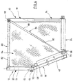
- FIG. 1 to 4 show two protective frames 10, 12 which consist of a lower frame section 14 and 16 and an upper frame section 18 and 20, respectively.
- the lower frame section 14 or 16 is provided with two parallel struts 22, 24 which are connected to cross struts 26, 28.
- the struts 22 to 28 consist of hollow profile material, for example a box profile.
- Fastening struts 30, 32 are also connected to the cross struts 26, 28 and run parallel and at a distance from the struts 22, 24. They are used to attach to a backrest of a passenger car, only shown schematically, for example of the caravan type. The attachment can be carried out, for example, by means of a snap connection 36, as is shown separately in FIG.
- the attachment of the lower frame part 16 to the separate rear seat 42 is analogous to that of the lower frame section 14, with guide rails 44, 46 also being embedded in the rear seat 42.
- the snap connection 36 is provided in the same way.
- the lower frame section 14, 16 can be lined up to the level of the upper edge of the seats 34, 42, for example in order to hide the guide rails.
- the struts 22, 24 have a free extension 50, 52 which engage in corresponding struts 54, 56 of the upper frame section 18 telescopically.
- the upper frame section 18 and 20 is shown completely pulled out. However, it can be lowered, the upper cross strut 58 or 60 being approximately at the top of the backrest 34, 42.
- section 50 is chamfered, as can be seen in dashed lines at 62.
- the upper frame section 20 can be pivoted vertically, while the lower frame section 16 is arranged in accordance with the inclination of the backrest 42.
- a stable screw 64 can be provided in the connection area in order to firmly connect the lower and upper frame sections 16, 20 to one another, both in the position according to FIG. 1 and also according to FIG. 2 (see also FIG. 4). For this, however, it is necessary to provide two different through holes in the section 50, 52.
- the cross struts 58, 60 can, as indicated by dash-dotted lines at 66, be screwed to the ceiling of the body or connected via a snap connection. Additionally or alternatively, it is possible to releasably connect the upper frame sections 18, 20 laterally to a pillar of the body by means of side attachments 68, 70 by means of a screw or snap connection. Finally, with the extension 68, 70, a telescopic rod 72 can be connected in an articulated manner, as indicated at 74, the telescopic rod 72 then being able to be connected horizontally in the vehicle to a rear pillar or another attachment option. For this, however, it is necessary that the length of the telescopic connection 72 can be set as desired.
- the protective frames 10, 12 are located on the back of the backrests of the rear seats with the frame sections 14, 16 bearing against the back of the backrest. 2, the backrests 34, 42 are folded towards the front seats.
- the frames 18, 20 are pushed forward with the help of the guide shoes, not shown, along the guide rails 38, 40 or 44, 46 against a stop (not shown), as a result of which the frames 18, 20 are located behind the front seats in the free edge area of the front folded backrest. In this position, they are also attached to the ceiling or to a pillar via the side extensions 68, 70.
- a releasable fixation of the lower frame section 14, 16 can be provided in order to prevent subsequent movement.
- This position of the protective frame is shown in Fig. 2.
- a third is shown in Figures 3 and 4.
- the frame 12 has the same position as in the position according to FIG. 1, ie behind the folded backrest of the one rear seat.
- the second frame 10 has a position as can be seen in FIG. 2, that is to say pushed forward behind the front seats (as can be seen, the front seats and also the position of the rear seats of the body as well the body parts not shown).
- a distance is thus created between the frames 10, 12, as can be seen in FIG. 4. This creates a gap through which objects can pass from the loading space to the seating area of the cabin.
- a connecting strut 80 is proposed (FIG.
- the connecting strut 80 supports the frames 10, 12 against each other.
- a roller is mounted, as indicated by dashed lines at 82.
- a net 84 for example made of carbon fibers, is rolled up on this. The net can be pulled off the roller 82 in the manner of a roller blind and fastened in a suitable manner to the floor of the vehicle (fastening not shown).
- a telescopic rod 86 which consists of a tube 88 and a rod 90 slidably received therein, is articulated at 92 on the connecting strut 80 at the upper end.
- the lower end of the rod 90 has an eyelet (shown in broken lines), which is designated by 94 and can be pushed onto a hook 96 on the floor of the vehicle.
- the telescopic rod is also an obstacle to the passage through the space between frames 10, 12.
- screws 96 are indicated with knurled head. As indicated in the embodiment according to FIG. 5, they can be taken up by the attachment 68, 70, as shown at 98. In this way, the attachment of the upper frame section 14, 16 to a pillar of the body can be accomplished particularly easily.
- FIG. 6 the connecting strut 80 with articulated telescopic strut 86 is shown separately.
- FIG. 7 shows a wrinkle of the connecting strut 80 constantly via a ring 100 on a round rod 102 which carries insert pieces 104, 106 at the ends.
- the telescopic tube 86 is also articulated via a ring 108.
- FIG. 7 shows the arrangement for the position according to FIG. 2, in which both frame parts 10, 20 are arranged behind the front sides.
- the right piece 106 is completely inserted into the hollow profile 60 and the left one releases the profile 58.
- a leaf spring 110 is attached above both with a centrally welded pin which engages in a slot (not shown) of the profile 60 and can be locked therein by suitable measures.
- a block 112 is mounted so as to be pivotable about the axis of the strut 80 in order to be optionally inserted into the associated lower hollow profile.
- the frame parts can be suitably filled, e.g. with a grid, a mesh of wire or textile fibers or the like to develop the protective effect on smaller objects.
Landscapes
- Engineering & Computer Science (AREA)
- Mechanical Engineering (AREA)
- Body Structure For Vehicles (AREA)
- Seats For Vehicles (AREA)
Applications Claiming Priority (2)
| Application Number | Priority Date | Filing Date | Title |
|---|---|---|---|
| DE4416456A DE4416456C1 (de) | 1994-05-10 | 1994-05-10 | Vorrichtung zur schutzweisen Abtrennung des Raumes hinter dem Vorder- oder Hintersitz eines Personenkraftfahrzeugs |
| DE4416456 | 1994-05-10 |
Publications (2)
| Publication Number | Publication Date |
|---|---|
| EP0683073A1 true EP0683073A1 (fr) | 1995-11-22 |
| EP0683073B1 EP0683073B1 (fr) | 1998-07-22 |
Family
ID=6517763
Family Applications (1)
| Application Number | Title | Priority Date | Filing Date |
|---|---|---|---|
| EP95106624A Expired - Lifetime EP0683073B1 (fr) | 1994-05-10 | 1995-05-03 | Séparation de protection de l'espace en arrière du siège avant ou arrière d'un véhicule |
Country Status (2)
| Country | Link |
|---|---|
| EP (1) | EP0683073B1 (fr) |
| DE (2) | DE4416456C1 (fr) |
Cited By (2)
| Publication number | Priority date | Publication date | Assignee | Title |
|---|---|---|---|---|
| GB2310173A (en) * | 1996-02-17 | 1997-08-20 | Baumeister & Ostler Gmbh & Co Kg | A safety device for the interior of a vehicle. |
| FR2989649A1 (fr) * | 2012-04-23 | 2013-10-25 | Peugeot Citroen Automobiles Sa | Cloisonnement d'un habitacle de vehicule |
Families Citing this family (7)
| Publication number | Priority date | Publication date | Assignee | Title |
|---|---|---|---|---|
| DE102004010142B4 (de) * | 2004-02-27 | 2017-11-23 | Volkswagen Ag | Trennwandanordnung für ein Fahrzeug zum Unterteilen des Fahrzeuginnenraumes |
| DE102005009126A1 (de) * | 2005-03-01 | 2006-09-07 | Keiper Gmbh & Co.Kg | Fahrzeugsitz mit zwei schwenkbaren Lehnen |
| FR2893561B1 (fr) * | 2005-11-21 | 2007-12-21 | Renault Sas | Mecanisme de verrouillage, notamment d'une rangee arriere de sieges d'un vehicule automobile |
| DE102006025818A1 (de) * | 2006-06-02 | 2007-12-06 | Bayerische Motoren Werke Ag | Trennwandeinrichtung zwischen dem Fahrgastraum eines Kraftfahrzeugs und einem hinteren Gepäckraum |
| DE102006058475A1 (de) | 2006-12-12 | 2008-07-10 | GM Global Technology Operations, Inc., Detroit | Kraftfahrzeuginneneinrichtung mit einem in eine Trennwandposition bringbaren Kraftfahrzeugsitz und Kraftfahrzeug mit einer solchen Kraftfahrzeuginneneinrichtung |
| FR3034367B1 (fr) * | 2015-03-31 | 2017-03-24 | Peugeot Citroen Automobiles Sa | Dispositif de liaison d’une cloison de protection mobile entraine par le coulissement d’un siege de vehicule |
| US12365299B2 (en) * | 2021-08-17 | 2025-07-22 | Westin Automotive Products, Inc. | Modular public safety vehicle security partition |
Citations (4)
| Publication number | Priority date | Publication date | Assignee | Title |
|---|---|---|---|---|
| FR1257096A (fr) * | 1960-01-26 | 1961-03-31 | Dispositif pour assurer la protection du chauffeur et de son compagnon contre l'agression venant de passagers disposés à l'arrière d'un véhicule | |
| US3214211A (en) * | 1964-01-27 | 1965-10-26 | John R Setina | Automobile partition apparatus |
| DE3635992A1 (de) * | 1985-11-15 | 1987-05-21 | Volkswagen Ag | Einrichtung zur befestigung eines rueckhaltesystems |
| DE4128555A1 (de) * | 1990-09-08 | 1992-03-12 | Volkswagen Ag | Anordnung mit einer schutzeinrichtung zwischen fahrgastraum und laderaum eines kombifahrzeuges |
Family Cites Families (1)
| Publication number | Priority date | Publication date | Assignee | Title |
|---|---|---|---|---|
| US4213636A (en) * | 1978-09-18 | 1980-07-22 | King William B | Safety barrier for a vehicle |
-
1994
- 1994-05-10 DE DE4416456A patent/DE4416456C1/de not_active Expired - Fee Related
-
1995
- 1995-05-03 EP EP95106624A patent/EP0683073B1/fr not_active Expired - Lifetime
- 1995-05-03 DE DE59502866T patent/DE59502866D1/de not_active Expired - Fee Related
Patent Citations (4)
| Publication number | Priority date | Publication date | Assignee | Title |
|---|---|---|---|---|
| FR1257096A (fr) * | 1960-01-26 | 1961-03-31 | Dispositif pour assurer la protection du chauffeur et de son compagnon contre l'agression venant de passagers disposés à l'arrière d'un véhicule | |
| US3214211A (en) * | 1964-01-27 | 1965-10-26 | John R Setina | Automobile partition apparatus |
| DE3635992A1 (de) * | 1985-11-15 | 1987-05-21 | Volkswagen Ag | Einrichtung zur befestigung eines rueckhaltesystems |
| DE4128555A1 (de) * | 1990-09-08 | 1992-03-12 | Volkswagen Ag | Anordnung mit einer schutzeinrichtung zwischen fahrgastraum und laderaum eines kombifahrzeuges |
Cited By (5)
| Publication number | Priority date | Publication date | Assignee | Title |
|---|---|---|---|---|
| GB2310173A (en) * | 1996-02-17 | 1997-08-20 | Baumeister & Ostler Gmbh & Co Kg | A safety device for the interior of a vehicle. |
| FR2744967A1 (fr) * | 1996-02-17 | 1997-08-22 | Baumeister & Ostler Gmbh Co | Dispositif de securite pour l'habitacle d'un vehicule automobile |
| GB2310173B (en) * | 1996-02-17 | 1998-09-23 | Baumeister & Ostler Gmbh Co | Safety device for the interior of a vehicle |
| US5876064A (en) * | 1996-02-17 | 1999-03-02 | Baumeister + Ostler Gmbh & Co. Kg | Protective device for an interior of a motor vehicle |
| FR2989649A1 (fr) * | 2012-04-23 | 2013-10-25 | Peugeot Citroen Automobiles Sa | Cloisonnement d'un habitacle de vehicule |
Also Published As
| Publication number | Publication date |
|---|---|
| EP0683073B1 (fr) | 1998-07-22 |
| DE4416456C1 (de) | 1995-09-14 |
| DE59502866D1 (de) | 1998-08-27 |
Similar Documents
| Publication | Publication Date | Title |
|---|---|---|
| DE19605907B4 (de) | Sicherungsvorrichtung für einen Innenraum eines Kraftfahrzeugs | |
| DE4316930C2 (de) | Sitzbank für Kraftfahrzeuge, insbesondere Wohnmobile | |
| DE10219764B4 (de) | Klappbare Fahrzeugbordwand mit daran befestigten Sitzkomponenten | |
| EP0001230B1 (fr) | Cabine de conduite habitable pour véhicules de transport à longue distance | |
| EP0407741A2 (fr) | Appui-tête pour sièges arrières | |
| DE3909397C2 (fr) | ||
| EP1123224A1 (fr) | Recouvrement destine a l'espace de chargement d'un vehicule automobile | |
| EP0779172B1 (fr) | Voiture convertible avec deux sièges avant et banquette arrière | |
| EP0683073A1 (fr) | Séparation de protection de l'espace en arrière du siège avant ou arrière d'un véhicule | |
| DE69104028T2 (de) | Lastsicherungsvorrichtung. | |
| DE10261393A1 (de) | Höhenverstellbares Laderaumbodensystem | |
| DE10392188T5 (de) | Fahrzeugsitz | |
| EP2910412A1 (fr) | Siège, en particulier siège de véhicule | |
| EP0289832A1 (fr) | Disposition de protection pour l'intérieur d'un véhicule automobile | |
| DE10057572C2 (de) | Laderaum-Abdeck- und/oder Laderaum-Trennvorrichtung für den Lade-oder Gepäckraum eines Fahrzeugs | |
| DE19937028A1 (de) | Fahrzeug mit einer Konsole für die Beifahrerseite | |
| DE4400934C1 (de) | Kraftwagen | |
| DE4128701A1 (de) | Schutzwand zur abtrennung des fahrgastraumes eines kraftfahrzeuges von einem dahinter gelegenen laderaum | |
| DE3529735A1 (de) | Lagerung einer kraftfahrzeug-hintersitzlehne | |
| DE102005013170A1 (de) | Fußauflage für Kraftfahrzeuge | |
| DE9308942U1 (de) | Sitzbank für Kraftfahrzeuge, insbesondere Wohnmobile | |
| DE10064793A1 (de) | Vorrichtung zur Anordnung eines Fahrzeugsitzes, insbesondere eines Beifahrersitzes, in seiner Nichtgebrauchsstellung innerhalb eines Fahrzeuges | |
| DE19509159A1 (de) | Kopfstützenanordnung | |
| DE19543349C1 (de) | Windschott für zwei Frontsitze eines offenen Personenkraftwagens | |
| DE2906988A1 (de) | Einstellvorrichtung fuer fahrzeugsicherheitsgurte |
Legal Events
| Date | Code | Title | Description |
|---|---|---|---|
| PUAI | Public reference made under article 153(3) epc to a published international application that has entered the european phase |
Free format text: ORIGINAL CODE: 0009012 |
|
| AK | Designated contracting states |
Kind code of ref document: A1 Designated state(s): DE FR IT SE |
|
| 17P | Request for examination filed |
Effective date: 19960509 |
|
| 17Q | First examination report despatched |
Effective date: 19970228 |
|
| GRAG | Despatch of communication of intention to grant |
Free format text: ORIGINAL CODE: EPIDOS AGRA |
|
| GRAG | Despatch of communication of intention to grant |
Free format text: ORIGINAL CODE: EPIDOS AGRA |
|
| GRAH | Despatch of communication of intention to grant a patent |
Free format text: ORIGINAL CODE: EPIDOS IGRA |
|
| GRAH | Despatch of communication of intention to grant a patent |
Free format text: ORIGINAL CODE: EPIDOS IGRA |
|
| GRAA | (expected) grant |
Free format text: ORIGINAL CODE: 0009210 |
|
| AK | Designated contracting states |
Kind code of ref document: B1 Designated state(s): DE FR IT SE |
|
| REF | Corresponds to: |
Ref document number: 59502866 Country of ref document: DE Date of ref document: 19980827 |
|
| ET | Fr: translation filed | ||
| PLBE | No opposition filed within time limit |
Free format text: ORIGINAL CODE: 0009261 |
|
| STAA | Information on the status of an ep patent application or granted ep patent |
Free format text: STATUS: NO OPPOSITION FILED WITHIN TIME LIMIT |
|
| 26N | No opposition filed | ||
| PGFP | Annual fee paid to national office [announced via postgrant information from national office to epo] |
Ref country code: SE Payment date: 20010502 Year of fee payment: 7 |
|
| PGFP | Annual fee paid to national office [announced via postgrant information from national office to epo] |
Ref country code: DE Payment date: 20010621 Year of fee payment: 7 |
|
| PG25 | Lapsed in a contracting state [announced via postgrant information from national office to epo] |
Ref country code: SE Free format text: LAPSE BECAUSE OF NON-PAYMENT OF DUE FEES Effective date: 20020504 |
|
| PGFP | Annual fee paid to national office [announced via postgrant information from national office to epo] |
Ref country code: FR Payment date: 20020628 Year of fee payment: 8 |
|
| PG25 | Lapsed in a contracting state [announced via postgrant information from national office to epo] |
Ref country code: DE Free format text: LAPSE BECAUSE OF NON-PAYMENT OF DUE FEES Effective date: 20021203 |
|
| EUG | Se: european patent has lapsed | ||
| PG25 | Lapsed in a contracting state [announced via postgrant information from national office to epo] |
Ref country code: FR Free format text: LAPSE BECAUSE OF NON-PAYMENT OF DUE FEES Effective date: 20040130 |
|
| REG | Reference to a national code |
Ref country code: FR Ref legal event code: ST |
|
| PG25 | Lapsed in a contracting state [announced via postgrant information from national office to epo] |
Ref country code: IT Free format text: LAPSE BECAUSE OF NON-PAYMENT OF DUE FEES Effective date: 20050503 |