EP0683073B1 - Séparation de protection de l'espace en arrière du siège avant ou arrière d'un véhicule - Google Patents
Séparation de protection de l'espace en arrière du siège avant ou arrière d'un véhicule Download PDFInfo
- Publication number
- EP0683073B1 EP0683073B1 EP95106624A EP95106624A EP0683073B1 EP 0683073 B1 EP0683073 B1 EP 0683073B1 EP 95106624 A EP95106624 A EP 95106624A EP 95106624 A EP95106624 A EP 95106624A EP 0683073 B1 EP0683073 B1 EP 0683073B1
- Authority
- EP
- European Patent Office
- Prior art keywords
- frame section
- section
- back rest
- protective
- strut
- Prior art date
- Legal status (The legal status is an assumption and is not a legal conclusion. Google has not performed a legal analysis and makes no representation as to the accuracy of the status listed.)
- Expired - Lifetime
Links
- 238000000638 solvent extraction Methods 0.000 title claims 2
- 230000001681 protective effect Effects 0.000 claims description 32
- 239000000463 material Substances 0.000 claims description 4
- 238000013459 approach Methods 0.000 description 6
- 238000000926 separation method Methods 0.000 description 4
- 229920000049 Carbon (fiber) Polymers 0.000 description 1
- 239000004917 carbon fiber Substances 0.000 description 1
- 238000010276 construction Methods 0.000 description 1
- 239000000835 fiber Substances 0.000 description 1
- 239000004753 textile Substances 0.000 description 1
- 230000037303 wrinkles Effects 0.000 description 1
Images


Classifications
-
- B—PERFORMING OPERATIONS; TRANSPORTING
- B60—VEHICLES IN GENERAL
- B60R—VEHICLES, VEHICLE FITTINGS, OR VEHICLE PARTS, NOT OTHERWISE PROVIDED FOR
- B60R21/00—Arrangements or fittings on vehicles for protecting or preventing injuries to occupants or pedestrians in case of accidents or other traffic risks
- B60R21/02—Occupant safety arrangements or fittings, e.g. crash pads
- B60R21/026—Rigid partitions inside vehicles, e.g. between passengers and load compartments
Definitions
- the invention relates to a device for protective separation of the Space behind the front or rear seat of a passenger car according to the generic term of claim 1.
- DE-A-36 35 992 describes a device for the protective separation of the aforementioned Kind become known in which a protective frame made of rigid material in one lower and an upper section is divided, the upper section in the lower Telescopically adjustable is the purpose of adjusting the protective frame. From DE-A-41 28 555 a similar protective frame has become known, in which the lower section is adjustable in a guide on the back of the backrest, also in to be able to form a protective frame when the backrest is folded down. In both In known cases, the upper frame section is releasably attachable to the body.
- the invention has for its object a device for protective separation the space behind the front or rear seats of a passenger car create that maintains its protective effect even with higher forces.
- the device according to the invention is on a side approach to the upper frame section a telescopically adjustable, fixed in any length Articulated strut to attach the frame section to a rear pillar or part of the body.
- the column is usually the most stable part in building one Body, so that high forces can act on the protective frame with the help of the strut, without giving in.
- the strut is only subjected to tension, can therefore considerable forces are transferred to the support or column to the rear.
- the side approach enables a corresponding use of space in the area of the passenger car for the protective frame, so that parts do not move laterally from one compartment to the other can occur, for example, during strong braking maneuvers or an impact or the like.
- the struts are shifted close to the outside Inside of the body, so that a restriction of the existing cargo space is not takes place.
- the wheel arches usually narrow the interior. The one described Construction takes this into account.
- the upper frame section can be made using screws or a Snap connection to the roof or laterally connected to the pillar of the body will.
- the backrest usually has a backward slope. Had the top frame section the same incline, this would result in a reduction in the loading space. Therefore, an embodiment of the invention provides that the lower facing Ends of the telescopically interacting profile sections are designed so that the upper frame section with the lower an obtuse angle forms and the upper frame section in the upper Position is arranged vertically. Those facing each other Ends of the hollow profiles can be according to a further embodiment the invention connected by a screw connection be that can be performed relatively stable. In this case, the protective frame can function as a roll bar take over.
- the backrests of the rear seats are folded forward, to enlarge the cargo space. Therefore sees an embodiment the invention that the lower frame portion in a second position on the back of the folded forward
- the backrest can be detachably attached to it is. With the backrest folded forward, it stands there the frame section at the free end of the backrest on, approximately at an angle of 90 °.
- the upper frame section who now has a position further ahead (behind the front seats) is also more appropriate at this point Way to connect to the body, for example with the ceiling or the pillars of the body With the help of a suitable snap or screw connection or similar.
- the bottom of the lower frame section is also more appropriate in this position Way to attach to the backrest.
- the split version of the Backrest folded forward only one backrest section be while the other is in its up position keeps.
- the invention Use protective device effectively.
- a connecting strut between the Protective frame sections is provided. This can be sent to the Ends have side lugs that fit into the Engage the hollow profile of the upper frame sections.
- the Connecting strut can also serve to connect a network bearing role. The network can then be processed according to Art a roller blind are pulled down to the bottom of the Motor vehicle and attached to it in a suitable manner will. This also creates a protective separation between created the two rear seats.
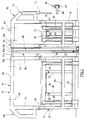
- FIG. 1 to 4 show two protective frames 10, 12, from a lower frame section 14 or 16 and an upper frame section 18 and 20 exist.
- the struts 22 to 28 consist of hollow profile material, for example a box profile.
- the Cross struts 26, 28 are also fastening struts 30, 32 connected in parallel and at a distance to the struts 22, 24 run. They are for attachment to one only schematically illustrated backrest of the rear seats Cars, for example of the caravan type.
- the attachment can for example by means of a snap connection 36, as shown separately in Fig.
- a Mandrel 38 which is in a resilient recess 40 with an undercut snaps into place.
- the cross strut 28 are sliding shoes connected (not visible) that in channel-like guides 38, 40 slide. In the position shown in Fig. 1 the shoes lie against a stop in the guide 38, 40 and therefore support the frame 10 downwards.
- the Snap connections 36 hold the lower frame portion 14 against the appropriately trained back of Backrest 34.
- the guide rails 38, 40 are preferably recessed in the backrest 34.
- the attachment of the lower frame part 16 on the separate Back seat 42 is analogous to that of the lower frame section 14, with guide rails also on the rear seat 42 44, 46 are embedded.
- the snap connection 36 is provided in the same way. Up to the top edge the seats 34, 42 may have the lower frame portion 14, 16 be lined, for example, to close the guide rails cover up.
- the struts 22, 24 have a free extension 50, 52, the corresponding struts 54, 56 of the upper frame section 18 intervene telescopically.
- the upper frame section 18 or 20 is completely pulled out shown. However, it can be lowered, whereby the upper cross strut 58 and 60 approximately at the level of the top the backrest 34, 42 is.
- section 50 beveled, as can be seen in dashed lines at 62.
- This can the upper frame section 20 is pivoted into the vertical be, while the lower frame portion 16 accordingly the inclination of the backrest 42 is arranged.
- a stable screw 64 can be provided, around lower and upper frame sections 16, 20 connect with each other, both in position 1 as well as that of FIG. 2 (see also FIG. 4).
- this requires two different ones To provide through holes in the section 50, 52.
- the cross struts 58, 60 can, as in dash-dotted lines at 66 indicated, screwed to the ceiling of the body or can be connected via a snap connection.
- the approach 68, 70 is articulated with a telescopic rod 72, as indicated at 74, with the telescopic rod 72 running horizontally in the vehicle with a rear pillar or another part of the body is connected.
- this requires that the length of the Telescopic connection 72 is permanently adjustable.
- Fig. 1 are the Protective frame 10, 12 on the back of the backrests Rear seats with the contact of the frame sections 14, 16 the back of the backrest.
- the backrests 34, 42 are in the direction of the front seats worked.
- the frame 18, 20 are with the help of guide shoes, not shown, along the guide rails 38, 40 or 44, 46 pushed forward against you Stop (not shown), whereby the frame 18, 20th behind the front seats in the free edge area folded backrest. You will be in this Position also on the ceiling or over the side Lugs 68, 70 attached to a column. Besides, can a releasable fixation of the lower frame section 14, 16 be provided to prevent backward movement.
- This position of the protective frame is shown in Fig. 2.
- a third is shown in Figures 3 and 4.
- the frame 12 has the same position as in the position according to FIG. 1, i.e. behind the folded back of one back seat.
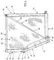
- the second frame 10 has a position as shown in Fig. 2, i.e. advanced behind the front seats (as can be seen, are the front seats and also the position of the rear seats of the body as well the body parts not shown). Between the frames 10, 12 a distance is thus created, as in Fig. 4 can be seen. This creates a gap through the passage from the cargo area to the cabin seating area of objects is possible.
- a connecting strut 80 is proposed (FIG. 4) which has lateral approaches at the ends, which in corresponding hollow profiles of the struts 58 (see also Fig.
- the connecting strut 80 supports the frames 10, 12 against each other.
- a roller is stored, as dashed lines indicated at 82.
- a network 84 for example made of carbon fibers, rolled up. The network can look after kind of a roller blind pulled from the roller 82 and suitable Way to be attached to the floor of the vehicle (attachment Not shown).
- a telescopic rod 86 consisting of a tube 88 and one slidable therein received rod 90, at the upper end at 92 is articulated on the connecting strut 80.
- the bottom end the rod 90 has an eyelet (shown in broken lines), which is designated 94 and on a hook 96 on the floor the vehicle can be pushed on.
- the telescopic pole is also an obstacle to the passage through the space between frames 10, 12.
- screws 96 are indicated with knurled head. she can, as in the embodiment of FIG. 5, hint is shown, are taken up by the approach 68, 70, as shown at 98. In this way it can be special simply attach the top frame section 14, 16 accomplish on a pillar of the body.
- the connecting strut 80 is articulated Telescopic strut 86 shown separately.
- Fig. 7 shows a wrinkle of the connecting strut 80 constantly via a ring 100 on a round rod 102, the the ends of insert pieces 104, 106 carries. Over a ring 108, the telescopic tube 86 is also articulated.
- Fig. 7 gives the arrangement for the position of FIG. 2 again, in the both frame parts 10, 20 arranged behind the front sides are.
- the right piece 106 is completely in that Hollow profile 60 inserted and the left gives the profile 58 free.
- a leaf spring 110 is attached over both with a centrally welded spigot that fits into one Slot (not shown) of profile 60 engages and in this can be locked by suitable measures.
- a block 112 is around the end of the connecting strut Axis of the strut 80 is pivotally mounted to either to be inserted into the associated lower hollow profile.
- the frame parts can be filled in a suitable manner be, e.g. with a grid, a wire mesh or Textile fibers or the like to the protective effect to unfold smaller objects.
Landscapes
- Engineering & Computer Science (AREA)
- Mechanical Engineering (AREA)
- Body Structure For Vehicles (AREA)
- Seats For Vehicles (AREA)
Claims (15)
- Séparation de protection de l'espace situé derrière les sièges avant ou les sièges arrière d'une voiture automobile, comportant les caractéristiques suivantes:a) un cadre de protection (10, 12) en matériau rigide est divisé en une partie inférieure et une partie supérieure (14, 16, 18, 20), lesdites parties pouvant être positionnées de façon téléscopique en étant guidées l'une contre l'autre, pour régler la position en hauteur du cadre de protection (10, 12);b) la partie inférieure (14, 16) du cadre, dans la position haute du dossier (34, 42) du siège arrière, peut être fixée sur la face arrière du dossier (34, 42), en contact par sa surface;c) la partie supérieure (18, 20) du cadre peut être positionée entre une position inférieure, dans laquelle elle est largement recouverte par le dossier (34, 42), et une position supérieure, dans laquelle elle touche le toít de la carrosserie, etd) la partie supérieure (18, 20) du cadre, dans sa position supérieure, peut être fixée de façon démontable sur une partie de la carrosserie,
caractérisée en ce que, sur un appendice latéral (68, 70) de la partie supérieure (18, 20) du cadre, s'articule une tige (72), réglable en longueur de façon télescopique et pouvant être bloquée à la longueur désirée, pour fixer la partie du cadre sur une colonne arrière ou une autre pièce de la carrosserie. - Séparation suivant la revendication 1, caractérisée en ce que, dans le cas d'un dossier (34, 42) divisé, un cadre de protection (10, 12) est associé à chaque partie du dossier.
- Séparation suivant la revendication 1 ou la revendication 2, caractérisée en ce que le cadre de protection (10, 12) est réalisé dans un matériau constitué de tiges profilées creuses et en ce que la liaison télescopique de la partie inférieure et de la partie supérieure (14, 16, 18, 20) du cadre est formée par des éléments de tige pouvant coulisser les uns dans les autres.
- Séparation suivant l'une des revendication 1 à 3, caractérisée en ce que la partie supérieure (18, 20) du cadre peut être reliée au toit ou à une colonne latérale de la carrosserie au moyen d'au moins une vis (66) ou d'une liaison à encliquetage (36).
- Séparation suivant l'une des revendications 1 à 4, caractérisée en ce que la partie supérieure (18, 20) du cadre possède, à son extrémité supérieure, du côté tourné vers la carrosserie, un appendice tubulaire (68, 70).
- Séparation suivant l'une des revendications 1 à 5, caractérisée en ce que les extrémités tournées l'une vers l'autre des parties profilées agissant ensemble de façon télescopique sont réalisées de telle façon que la partie supérieure (28) du cadre forme, avec la partie inférieure, un angle obtus et que la partie supérieure (28) du cadre est disposée de façon sensiblement verticale quand elle est dans sa position haute.
- Séparation suivant la revendication 6, caractérisée en ce que les extrémités des profilés creux peuvent être fixées les uns par rapport aux autres au moyen d'une liaison par vis (64).
- Séparation suivant l'une des revendications 1 à 7, caractérisée en ce que la partie inférieure (14, 16) du cadre peut, dans une deuxième position, être placée debout sur la face arrière du dossier (34, 42) basculé vers l'avant, en étant amovible par rapport à ce dernier.
- Séparation suivant la revendication 8, caractérisée en ce que, dans le dossier (34, 42) est placé un guidage (38, 40, 44, 46) sur lequel peut être réglé par coulissement un élément de guidage de la partie inférieure (14, 16) du cadre, entre une butée située dans la zone inférieure et une butée située dans la zone supérieure du dossier (34, 42).
- Séparation suivant la revendication 9, caractérisée en ce que le guidage est constitué d'au moins deux rails en forme de canal, disposés à une certaine distance parallèlement l'un à l'autre, et dans lesquels sont guidés des sabots de glissement, ou similaires, de la partie inférieure (14, 16) du cadre.
- Séparation suivant la revendication 2 et l'une des revendications 8 à 10, caractérisée en ce que, dans le cas d'un cadre de protection (10) en position avant et d'un cadre de protection (12) en position arrière, les parties supérieures (18, 20) de cadre peuvent être reliées par une tige de liaison (80).
- Séparation suivant la revendication 11, caractérisée en ce que la tige (80) présente, à ses extrémités, à une certaine distance, des parties sensiblement verticales, qui s'engagent, dans le profilé creux de la partie supérieure (18, 20) du cadre, en s'ajustant sensiblement.
- Séparation suivant la revendication 11 ou la revendication 12, caractérisée en ce que, dans la tige de liaison (80), est monté un rouleau (82) présentant un filet (84) déroulable, ou similaire, et en ce que, sur le bord inférieur du filet (84), sont prévus des moyens pour le raccordement à la carrosserie.
- Séparation suivant l'une des revendications 11 à 13, caractérisée en ce qu'à une extrémité de la tige (80), s'articule une tige télescopique (86), qui s'étend depuis la partie de bordure supérieure (18), située en position avant, jusqu'à un endroit de raccordement (96) dans la zone du dossier, enclenché en position haute.
- Séparation suivant l'une des revendications 1 à 14, caractérisée en ce qu'entre la partie inférieure (14, 16) du cadre et la face arrière du dossier (34, 42) agissent des moyens de liaison à encliquetage (36, 48), pour maintenir la partie inférieure (14, 16) du cadre au contact du dossier (34, 42).
Applications Claiming Priority (2)
| Application Number | Priority Date | Filing Date | Title |
|---|---|---|---|
| DE4416456A DE4416456C1 (de) | 1994-05-10 | 1994-05-10 | Vorrichtung zur schutzweisen Abtrennung des Raumes hinter dem Vorder- oder Hintersitz eines Personenkraftfahrzeugs |
| DE4416456 | 1994-05-10 |
Publications (2)
| Publication Number | Publication Date |
|---|---|
| EP0683073A1 EP0683073A1 (fr) | 1995-11-22 |
| EP0683073B1 true EP0683073B1 (fr) | 1998-07-22 |
Family
ID=6517763
Family Applications (1)
| Application Number | Title | Priority Date | Filing Date |
|---|---|---|---|
| EP95106624A Expired - Lifetime EP0683073B1 (fr) | 1994-05-10 | 1995-05-03 | Séparation de protection de l'espace en arrière du siège avant ou arrière d'un véhicule |
Country Status (2)
| Country | Link |
|---|---|
| EP (1) | EP0683073B1 (fr) |
| DE (2) | DE4416456C1 (fr) |
Cited By (1)
| Publication number | Priority date | Publication date | Assignee | Title |
|---|---|---|---|---|
| DE102006058475A1 (de) | 2006-12-12 | 2008-07-10 | GM Global Technology Operations, Inc., Detroit | Kraftfahrzeuginneneinrichtung mit einem in eine Trennwandposition bringbaren Kraftfahrzeugsitz und Kraftfahrzeug mit einer solchen Kraftfahrzeuginneneinrichtung |
Families Citing this family (8)
| Publication number | Priority date | Publication date | Assignee | Title |
|---|---|---|---|---|
| DE19605907B4 (de) * | 1996-02-17 | 2005-11-03 | Bos Gmbh & Co. Kg | Sicherungsvorrichtung für einen Innenraum eines Kraftfahrzeugs |
| DE102004010142B4 (de) * | 2004-02-27 | 2017-11-23 | Volkswagen Ag | Trennwandanordnung für ein Fahrzeug zum Unterteilen des Fahrzeuginnenraumes |
| DE102005009126A1 (de) * | 2005-03-01 | 2006-09-07 | Keiper Gmbh & Co.Kg | Fahrzeugsitz mit zwei schwenkbaren Lehnen |
| FR2893561B1 (fr) * | 2005-11-21 | 2007-12-21 | Renault Sas | Mecanisme de verrouillage, notamment d'une rangee arriere de sieges d'un vehicule automobile |
| DE102006025818A1 (de) * | 2006-06-02 | 2007-12-06 | Bayerische Motoren Werke Ag | Trennwandeinrichtung zwischen dem Fahrgastraum eines Kraftfahrzeugs und einem hinteren Gepäckraum |
| FR2989649A1 (fr) * | 2012-04-23 | 2013-10-25 | Peugeot Citroen Automobiles Sa | Cloisonnement d'un habitacle de vehicule |
| FR3034367B1 (fr) * | 2015-03-31 | 2017-03-24 | Peugeot Citroen Automobiles Sa | Dispositif de liaison d’une cloison de protection mobile entraine par le coulissement d’un siege de vehicule |
| US12365299B2 (en) * | 2021-08-17 | 2025-07-22 | Westin Automotive Products, Inc. | Modular public safety vehicle security partition |
Family Cites Families (5)
| Publication number | Priority date | Publication date | Assignee | Title |
|---|---|---|---|---|
| FR1257096A (fr) * | 1960-01-26 | 1961-03-31 | Dispositif pour assurer la protection du chauffeur et de son compagnon contre l'agression venant de passagers disposés à l'arrière d'un véhicule | |
| US3214211A (en) * | 1964-01-27 | 1965-10-26 | John R Setina | Automobile partition apparatus |
| US4213636A (en) * | 1978-09-18 | 1980-07-22 | King William B | Safety barrier for a vehicle |
| DE3635992C2 (de) * | 1985-11-15 | 1995-09-07 | Volkswagen Ag | Vorrichtung zur Befestigung eines Rückhaltesystems |
| DE4128555A1 (de) * | 1990-09-08 | 1992-03-12 | Volkswagen Ag | Anordnung mit einer schutzeinrichtung zwischen fahrgastraum und laderaum eines kombifahrzeuges |
-
1994
- 1994-05-10 DE DE4416456A patent/DE4416456C1/de not_active Expired - Fee Related
-
1995
- 1995-05-03 EP EP95106624A patent/EP0683073B1/fr not_active Expired - Lifetime
- 1995-05-03 DE DE59502866T patent/DE59502866D1/de not_active Expired - Fee Related
Cited By (1)
| Publication number | Priority date | Publication date | Assignee | Title |
|---|---|---|---|---|
| DE102006058475A1 (de) | 2006-12-12 | 2008-07-10 | GM Global Technology Operations, Inc., Detroit | Kraftfahrzeuginneneinrichtung mit einem in eine Trennwandposition bringbaren Kraftfahrzeugsitz und Kraftfahrzeug mit einer solchen Kraftfahrzeuginneneinrichtung |
Also Published As
| Publication number | Publication date |
|---|---|
| DE4416456C1 (de) | 1995-09-14 |
| DE59502866D1 (de) | 1998-08-27 |
| EP0683073A1 (fr) | 1995-11-22 |
Similar Documents
| Publication | Publication Date | Title |
|---|---|---|
| DE19605907B4 (de) | Sicherungsvorrichtung für einen Innenraum eines Kraftfahrzeugs | |
| DE102012112527B3 (de) | Nutzfahrzeugsitz mit integrierter Drehverstelleinrichtung | |
| DE102008060747B4 (de) | Bedarfsitz für ein Kraftfahrzeug | |
| AT518405B1 (de) | Fahrerhauslagerung für ein kippbares Fahrerhaus eines Nutzfahrzeugs | |
| DE3242593A1 (de) | Hoehenverstellvorrichtung fuer einen kraftfahrzeug-sicherheitsgurt | |
| EP1449711A2 (fr) | Siège pliable pour véhicules automobiles | |
| EP0683073B1 (fr) | Séparation de protection de l'espace en arrière du siège avant ou arrière d'un véhicule | |
| DE10359226A1 (de) | Rollstuhl-Halterungssystem | |
| DE10261393A1 (de) | Höhenverstellbares Laderaumbodensystem | |
| EP2910412B1 (fr) | Siège, en particulier siège de véhicule | |
| DE20016393U1 (de) | Klapptisch für Land-, Wasser- und Luftfahrzeuge | |
| EP0289832A1 (fr) | Disposition de protection pour l'intérieur d'un véhicule automobile | |
| DE10057572C2 (de) | Laderaum-Abdeck- und/oder Laderaum-Trennvorrichtung für den Lade-oder Gepäckraum eines Fahrzeugs | |
| DE4400934C1 (de) | Kraftwagen | |
| DE3607724C1 (en) | Slide for a deploying lever of a tilt-and-slide sun roof | |
| DE3018060A1 (de) | Handgriff fuer die insassen von fahrzeugen | |
| DE69814570T2 (de) | Anordnung für einen ausnehmbaren und in Längsrichtung verstellbaren Sitz im Innenraum eines Kraftfahrzeuges | |
| DE10038813A1 (de) | Kopfstützenanordnung | |
| DE3529735A1 (de) | Lagerung einer kraftfahrzeug-hintersitzlehne | |
| DE102005013170A1 (de) | Fußauflage für Kraftfahrzeuge | |
| DE9308942U1 (de) | Sitzbank für Kraftfahrzeuge, insbesondere Wohnmobile | |
| DE2931875C2 (de) | Sicherheitsgurtvorrichtung für den Insassen eines Fahrzeugs | |
| EP0960764B1 (fr) | Dispositif pour régler la hauteur d'un siège de véhicule | |
| DE69628531T2 (de) | Fahrzeugrücksitz | |
| DE10064793A1 (de) | Vorrichtung zur Anordnung eines Fahrzeugsitzes, insbesondere eines Beifahrersitzes, in seiner Nichtgebrauchsstellung innerhalb eines Fahrzeuges |
Legal Events
| Date | Code | Title | Description |
|---|---|---|---|
| PUAI | Public reference made under article 153(3) epc to a published international application that has entered the european phase |
Free format text: ORIGINAL CODE: 0009012 |
|
| AK | Designated contracting states |
Kind code of ref document: A1 Designated state(s): DE FR IT SE |
|
| 17P | Request for examination filed |
Effective date: 19960509 |
|
| 17Q | First examination report despatched |
Effective date: 19970228 |
|
| GRAG | Despatch of communication of intention to grant |
Free format text: ORIGINAL CODE: EPIDOS AGRA |
|
| GRAG | Despatch of communication of intention to grant |
Free format text: ORIGINAL CODE: EPIDOS AGRA |
|
| GRAH | Despatch of communication of intention to grant a patent |
Free format text: ORIGINAL CODE: EPIDOS IGRA |
|
| GRAH | Despatch of communication of intention to grant a patent |
Free format text: ORIGINAL CODE: EPIDOS IGRA |
|
| GRAA | (expected) grant |
Free format text: ORIGINAL CODE: 0009210 |
|
| AK | Designated contracting states |
Kind code of ref document: B1 Designated state(s): DE FR IT SE |
|
| REF | Corresponds to: |
Ref document number: 59502866 Country of ref document: DE Date of ref document: 19980827 |
|
| ET | Fr: translation filed | ||
| PLBE | No opposition filed within time limit |
Free format text: ORIGINAL CODE: 0009261 |
|
| STAA | Information on the status of an ep patent application or granted ep patent |
Free format text: STATUS: NO OPPOSITION FILED WITHIN TIME LIMIT |
|
| 26N | No opposition filed | ||
| PGFP | Annual fee paid to national office [announced via postgrant information from national office to epo] |
Ref country code: SE Payment date: 20010502 Year of fee payment: 7 |
|
| PGFP | Annual fee paid to national office [announced via postgrant information from national office to epo] |
Ref country code: DE Payment date: 20010621 Year of fee payment: 7 |
|
| PG25 | Lapsed in a contracting state [announced via postgrant information from national office to epo] |
Ref country code: SE Free format text: LAPSE BECAUSE OF NON-PAYMENT OF DUE FEES Effective date: 20020504 |
|
| PGFP | Annual fee paid to national office [announced via postgrant information from national office to epo] |
Ref country code: FR Payment date: 20020628 Year of fee payment: 8 |
|
| PG25 | Lapsed in a contracting state [announced via postgrant information from national office to epo] |
Ref country code: DE Free format text: LAPSE BECAUSE OF NON-PAYMENT OF DUE FEES Effective date: 20021203 |
|
| EUG | Se: european patent has lapsed | ||
| PG25 | Lapsed in a contracting state [announced via postgrant information from national office to epo] |
Ref country code: FR Free format text: LAPSE BECAUSE OF NON-PAYMENT OF DUE FEES Effective date: 20040130 |
|
| REG | Reference to a national code |
Ref country code: FR Ref legal event code: ST |
|
| PG25 | Lapsed in a contracting state [announced via postgrant information from national office to epo] |
Ref country code: IT Free format text: LAPSE BECAUSE OF NON-PAYMENT OF DUE FEES Effective date: 20050503 |