EP0683219B1 - Verfahren zur lufgeblasenen Vergasung von kohlenstoffhaltigen Brennstoffen - Google Patents
Verfahren zur lufgeblasenen Vergasung von kohlenstoffhaltigen Brennstoffen Download PDFInfo
- Publication number
- EP0683219B1 EP0683219B1 EP95810292A EP95810292A EP0683219B1 EP 0683219 B1 EP0683219 B1 EP 0683219B1 EP 95810292 A EP95810292 A EP 95810292A EP 95810292 A EP95810292 A EP 95810292A EP 0683219 B1 EP0683219 B1 EP 0683219B1
- Authority
- EP
- European Patent Office
- Prior art keywords
- gasification
- flow
- fuel
- mixture
- air
- Prior art date
- Legal status (The legal status is an assumption and is not a legal conclusion. Google has not performed a legal analysis and makes no representation as to the accuracy of the status listed.)
- Expired - Lifetime
Links
Images


Classifications
-
- C—CHEMISTRY; METALLURGY
- C10—PETROLEUM, GAS OR COKE INDUSTRIES; TECHNICAL GASES CONTAINING CARBON MONOXIDE; FUELS; LUBRICANTS; PEAT
- C10J—PRODUCTION OF PRODUCER GAS, WATER-GAS, SYNTHESIS GAS FROM SOLID CARBONACEOUS MATERIAL, OR MIXTURES CONTAINING THESE GASES; CARBURETTING AIR OR OTHER GASES
- C10J3/00—Production of combustible gases containing carbon monoxide from solid carbonaceous fuels
- C10J3/46—Gasification of granular or pulverulent flues in suspension
- C10J3/48—Apparatus; Plants
- C10J3/485—Entrained flow gasifiers
- C10J3/487—Swirling or cyclonic gasifiers
-
- C—CHEMISTRY; METALLURGY
- C10—PETROLEUM, GAS OR COKE INDUSTRIES; TECHNICAL GASES CONTAINING CARBON MONOXIDE; FUELS; LUBRICANTS; PEAT
- C10J—PRODUCTION OF PRODUCER GAS, WATER-GAS, SYNTHESIS GAS FROM SOLID CARBONACEOUS MATERIAL, OR MIXTURES CONTAINING THESE GASES; CARBURETTING AIR OR OTHER GASES
- C10J2200/00—Details of gasification apparatus
- C10J2200/15—Details of feeding means
- C10J2200/152—Nozzles or lances for introducing gas, liquids or suspensions
-
- C—CHEMISTRY; METALLURGY
- C10—PETROLEUM, GAS OR COKE INDUSTRIES; TECHNICAL GASES CONTAINING CARBON MONOXIDE; FUELS; LUBRICANTS; PEAT
- C10J—PRODUCTION OF PRODUCER GAS, WATER-GAS, SYNTHESIS GAS FROM SOLID CARBONACEOUS MATERIAL, OR MIXTURES CONTAINING THESE GASES; CARBURETTING AIR OR OTHER GASES
- C10J2300/00—Details of gasification processes
- C10J2300/12—Heating the gasifier
- C10J2300/1223—Heating the gasifier by burners
-
- C—CHEMISTRY; METALLURGY
- C10—PETROLEUM, GAS OR COKE INDUSTRIES; TECHNICAL GASES CONTAINING CARBON MONOXIDE; FUELS; LUBRICANTS; PEAT
- C10J—PRODUCTION OF PRODUCER GAS, WATER-GAS, SYNTHESIS GAS FROM SOLID CARBONACEOUS MATERIAL, OR MIXTURES CONTAINING THESE GASES; CARBURETTING AIR OR OTHER GASES
- C10J2300/00—Details of gasification processes
- C10J2300/18—Details of the gasification process, e.g. loops, autothermal operation
- C10J2300/1861—Heat exchange between at least two process streams
-
- F—MECHANICAL ENGINEERING; LIGHTING; HEATING; WEAPONS; BLASTING
- F23—COMBUSTION APPARATUS; COMBUSTION PROCESSES
- F23C—METHODS OR APPARATUS FOR COMBUSTION USING FLUID FUEL OR SOLID FUEL SUSPENDED IN A CARRIER GAS OR AIR
- F23C2900/00—Special features of, or arrangements for combustion apparatus using fluid fuels or solid fuels suspended in air; Combustion processes therefor
- F23C2900/07002—Premix burners with air inlet slots obtained between offset curved wall surfaces, e.g. double cone burners
Definitions
- Oxygen-blown processes for example Shell coal gasification processes, are currently mainly used for gasifying coal or residual oil. These processes produce a gas with a relatively high calorific value, 12-15 MJ / kg, which, due to its low mass flows, can be desulphurized without great loss of enthalpy and can be dedusted by washing equipment.
- the typical gasification reactions run CH4 + H2O ⁇ CO + 3H2 C + H2O ⁇ CO + H2 endothermic.
- the energy required is, for example, by exothermic reaction 2C + O2 ⁇ 2CO made available.
- the process is carried out with the help of a gasification tank carried out, in which a combustion Swirl flow is generated. It is in a swirl burner a substoichiometric fuel / air mixture on the axis burned, being essentially the exothermic reaction (3b) expires. Countercurrent is in the outer radius area also fuel with superheated steam at 700-1200 ° C gasified after the endothermic reactions (1) and (2). Due to the stable layering in the cylindrical reaction chamber it is avoided that the energy supplying partial flow in the Center where the combustion temperature is around 1800 ° C, with the fuel / steam mixture to be gasified in outer radius area mixes.
- An advantage of the invention can be seen in the fact that two-stage combustion control is possible, including fuels use with fuel-bound nitrogen, without in the exhaust gas maintain high nitrogen oxide levels.
Landscapes
- Chemical & Material Sciences (AREA)
- Engineering & Computer Science (AREA)
- Combustion & Propulsion (AREA)
- Oil, Petroleum & Natural Gas (AREA)
- Organic Chemistry (AREA)
- Combustion Of Fluid Fuel (AREA)
Description
Die benötigte Energie wird z.B. durch exotherme Reaktion
Bei einem luftgeblasenen Vergasungsprozess gemäss Stand der Technik würde die exotherme Reaktion (3a) zu:
- Es wird keine Luftzerlegungsanlage mehr benötigt;
- Das Verfahren kann sowohl atmosphärisch als auch unter Druck betrieben werden;
- Es entsteht ein Vergasungsprodukt mit einem moderaten Heizwert ≈ 10 MJ/kg, das in einer Gasturbine schadstoffarm verbrannt werden kann.
- Fig. 1
- einen zylindrischen Vergasungsbehälter, in welchem ein Vergasungsprodukt mit einem Heizwert ≈ 10 MJ/kg bereitgestellt wird,
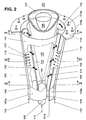
- Fig. 2
- einen Vormischbrenner in der Ausführung als "Doppelkegelbrenner" in perspektivischer Darstellung, entsprechend aufgeschnitten und
- Fig. 3-5
- Schnitte durch verschiedene Ebenen des Vormischbrenners gemäss Fig. 2.
- Radial geschichtete Drallströmung mit heissem Kern geringerer Dichte und kälterer Aussenströmung hoher Dichte.
- Gestufte Verbrennungsführung zur Minimierung der NOx-Emissionen.
- Strahlungswärmeaustausch zwischen unterstöchiometrischem heissem Kern und Reaktionsraumwand bzw. direkter Strahlungswärmeaustausch zwischen heissem Kern und VergasungsGemisch.
- 1
- Vergasungsbehälter
- 2
- Reaktionsraum
- 3
- Durchflussraum
- 4
- Zwischenrohr
- 5
- Heissgase, Heissgas-Schichtung
- 5a
- Neue Heissgase
- 6
- Zentrum, Kern
- 7
- Oeffnungen
- 8
- Sekundärluft
- 9
- Dampf
- 10
- Drallkörper
- 11
- Vergasungsgemisch
- 12
- Drallkörper
- 13
- Primärluft
- 14
- Abgasen
- 15
- Brennstoff
- 100
- Vormischbrenner
- 101, 102
- Teilkörper
- 101a, 102a
- Zylindrische Angangsteile
- 101b, 102b
- Längssymmetrieachsen
- 103
- Brennstoffdüse
- 104
- Brennstoffeindüsung
- 105
- Brennstoffeindüsungsprofil
- 106
- Rückströmzone (Vortex Breakdown)
- 107
- Flammenfront
- 108, 109
- Brennstoffleitungen
- 110
- Frontwand
- 110a
- Luftbohrungen
- 110b
- Kühlluft
- 112
- Flüssiger Brennstoff
- 113
- Gasförmiger Brennstoff
- 114
- Kegelhohlraum
- 115
- Verbrennungsluft
- 116
- Brennstoff-Eindüsung
- 117
- Brennstoffdüsen
- 119, 120
- Tangentiale Lufteintrittsschlitze
- 121a, 121b
- Leitbleche
- 122
- Brennraum
- 123
- Drehpunkt der Leitbleche
Claims (8)
- Verfahren zur luftgeblasenen Vergasung von kohlenstoffhaltigen Brennstoffen, wobei die benötigte Energie für die Vergasung durch Wärmeaustausch zwischen einer endothermen und einer exothermen Reaktion bereitgestellt wird, wobei durch die exotherme Reaktion aus der Verbrennung eines unterstöchiometrischen Brennstoff/Luft-Gemisches ein Heissgas entsteht, und durch die endotherme Reaktion aus einem Vergasungsprozess zwischen einem Brennstoff und überhitztem Dampf ein Vergasungsgemisch entsteht, dadurch gekennzeichnet, dass das Brennstoff/Luft-Gemisch zentral verdrallt in einen Reaktionsraum einströmt, wodurch eine zentrale verdrallte Heissgasströmung in Längsrichtung des Reaktionsraumes erzeugt wird, dass das Vergasungsgemisch in Längsrichtung entgegengesetzt zu der Heissgasströmung ringförmig verdrallt in den Reaktionsraum eingebracht wird, wodurch in einem gemeinsamen Reaktionsraum das Vergasungsgemisch als in Längsrichtung im Gegenstrom strömende verdrallte Ringströmung die verdrallte zentrale Heissgasströmung ummantelt, und dass der Wärmeaustausch durch Strahlungswärme zwischen dem Heissgas und dem Vergasungsgemisch bewerkstelligt wird.
- Verfahren nach Anspruch 1, dadurch gekennzeichnet, dass dem Heissgas nach dem Wärmetauschverfahren eine Sekundärluft zugemischt wird, dass dieses neue Heissgas im Wärmetauschverfahren den überhitzten Dampf aufbereitet und als Abgas abströmt, und dass das Vergasungsgemisch im Wärmetauschverfahren eine Primärluft aufwärmt und anschliessend als Brennstoff abströmt.
- Vorrichtung zur Durchführung eines Verfahrens zur luftgeblasenen Vergasung von kohlenstoffhaltigen Brennstoffen, wobei die Vorrichtung im wesentlichen aus einem Vergasungsbehälter besteht, dadurch gekennzeichnet, dass der Vergasungsbehälter (1) aus einem Reaktionsraum (2), einem in Strömungsrichtung der Heissgase (5) nachgeschalteten Zwischenstück (4) und einem Durchflussraum (3) besteht, dass kopfseitig des Reaktionsraumes (2) ein Brenner (100) angeordnet ist, der eine zentrale verdrallte Heissgas-Strömung (5) in Längsrichtung des Reaktionsraumes (2) erzeugt, dass das Zwischenstück (4) eine Reihe von in Umfangsrichtung angeordneten Drallkörpern (10) aufweist, welche das dort durchströmende Vergasungsgemisch (11) verdrallen, und dass die Heissgase (5) von diesem Vergasungsgemisch (11) in entgegengesetzter Strömungsrichtung ummantelt sind.
- Vorrichtung nach Anspruch 3, dadurch gekennzeichnet, dass der Brenner (100) aus mindestens zwei hohlen, kegelförmigen, in Strömungsrichtung ineinandergeschachtelten Teilkörpern (101, 102) besteht, deren jeweilige Längssymmetrieachsen (101b, 102b) gegeneinander versetzt verlaufen, dass die benachbarten Wandungen der Teilkörper (101, 102) in deren Längserstrekkung tangentiale Kanäle (119, 120) für einen Verbrennungsluftstrom (115) bilden, dass im von den Teilkörpern (101, 102) gebildeten Kegelhohlraum (114) mindestens eine Brennstoffdüse (103) vorhanden ist.
- Vorrichtung nach Anspruch 4, dadurch gekennzeichnet, dass im Bereich der tangentialen Kanäle (119, 120) in deren Längserstreckung weitere Brennstoffdüsen (117) angeordnet sind.
- Vorrichtung nach Anspruch 4, dadurch gekennzeichnet, dass sich die Teilkörper (101, 102) in Strömungsrichtung unter einem festen Winkel kegelig erweitern.
- Vorrichtung nach Anspruch 4, dadurch gekennzeichnet, dass die Teilkörper (101, 102) in Strömungsrichtung eine zunehmende Kegelneigung aufweisen.
- Vorrichtung nach Anspruch 4, dadurch gekennzeichnet, dass die Teilkörper (101, 102) in Strömungsrichtung eine abnehmende Kegelneigung aufweisen.
Applications Claiming Priority (2)
| Application Number | Priority Date | Filing Date | Title |
|---|---|---|---|
| DE4417539A DE4417539A1 (de) | 1994-05-19 | 1994-05-19 | Verfahren zur luftgeblasenen Vergasung von kohlenstoffhaltigen Brennstoffen |
| DE4417539 | 1994-05-19 |
Publications (3)
| Publication Number | Publication Date |
|---|---|
| EP0683219A2 EP0683219A2 (de) | 1995-11-22 |
| EP0683219A3 EP0683219A3 (de) | 1996-01-10 |
| EP0683219B1 true EP0683219B1 (de) | 2001-07-25 |
Family
ID=6518483
Family Applications (1)
| Application Number | Title | Priority Date | Filing Date |
|---|---|---|---|
| EP95810292A Expired - Lifetime EP0683219B1 (de) | 1994-05-19 | 1995-05-03 | Verfahren zur lufgeblasenen Vergasung von kohlenstoffhaltigen Brennstoffen |
Country Status (3)
| Country | Link |
|---|---|
| US (1) | US5656043A (de) |
| EP (1) | EP0683219B1 (de) |
| DE (2) | DE4417539A1 (de) |
Families Citing this family (4)
| Publication number | Priority date | Publication date | Assignee | Title |
|---|---|---|---|---|
| US6920988B1 (en) * | 2003-01-29 | 2005-07-26 | Calvin A. Ratliff | Towel bar, ring or hook anchoring device and wet towel shield |
| US8888872B2 (en) * | 2010-07-06 | 2014-11-18 | General Electric Company | Gasifier cooling system |
| US10920987B2 (en) * | 2016-08-18 | 2021-02-16 | Mf Fire, Inc. | Apparatus and method for burning solid fuel |
| EP3747537A1 (de) * | 2019-06-06 | 2020-12-09 | CMI UVK GmbH | Reaktor zur behandlung einer metallhaltigen säurelösung, insbesondere eines beizschlamms, und/oder zum regenerieren einer säurekomponente aus einer metallhaltigen säurelösung, vorwärmer, vorrichtung und verfahren |
Family Cites Families (29)
| Publication number | Priority date | Publication date | Assignee | Title |
|---|---|---|---|---|
| US1530281A (en) * | 1923-07-26 | 1925-03-17 | Murrie John Lester | Manufacture of gas |
| US1963167A (en) * | 1928-04-02 | 1934-06-19 | Heller Max | Method of and apparatus for generating water gas from pulverized fuel |
| US2028946A (en) * | 1929-11-02 | 1936-01-28 | Phelps Dodge Corp | Gas generator |
| US2038657A (en) * | 1930-10-04 | 1936-04-28 | Sylvia Remsen Hillhouse | Method for making gas |
| US2010634A (en) * | 1931-12-28 | 1935-08-06 | Sylvia Remsen Hillhouse | Method of making water gas |
| US2011339A (en) * | 1932-11-10 | 1935-08-13 | Sylvia Remsen Hillhouse | Method of screening combustion from materials heated thereby |
| US2085510A (en) * | 1934-05-08 | 1937-06-29 | Henry L Rosenfeld Jr | Apparatus for generating fuel gas |
| US2077236A (en) * | 1934-08-31 | 1937-04-13 | Walter B Harris | Oil gas generator |
| US2656264A (en) * | 1947-08-28 | 1953-10-20 | Inst Gas Technology | Manufacture of calorific gas |
| US2675295A (en) * | 1949-05-12 | 1954-04-13 | Daniels Joseph | Process for rapidly and continuously performing a high temperature endothermic reaction between a solid and a gaseous reactant |
| US2684896A (en) * | 1950-10-10 | 1954-07-27 | Texas Co | Process for the production of carbon monoxide and hydrogen |
| LU31508A1 (de) * | 1951-07-14 | |||
| US3009795A (en) * | 1958-11-10 | 1961-11-21 | Texaco Inc | Gasification of solid carbonaceous materials |
| EP0001857A1 (de) * | 1977-10-31 | 1979-05-16 | PPS Polyvalent Patent Service AG, | Anlage und Verfahren zur kontinuierlichen Erzeugung von hochwertigem Generator- und Wassergas |
| US4150953A (en) * | 1978-05-22 | 1979-04-24 | General Electric Company | Coal gasification power plant and process |
| JPS58206687A (ja) * | 1982-05-26 | 1983-12-01 | Sanwa Kigyo Kk | 液状石炭の水性ガス化装置並びにその方法、関連還元装置並びにその方法及び脱硫方法 |
| US4490157A (en) * | 1983-01-10 | 1984-12-25 | Combustion Engineering, Inc. | Indirectly heated fluidized bed gasifier |
| EP0144094B1 (de) * | 1983-12-07 | 1988-10-19 | Kabushiki Kaisha Toshiba | Verbrennungsmethode mit verringertem Stickoxyd-Ausstoss |
| AT384007B (de) * | 1984-04-02 | 1987-09-25 | Voest Alpine Ag | Verfahren zur herstellung von synthesegasen sowie vorrichtung zur durchfuehrung des verfahrens |
| US4737161A (en) * | 1987-01-27 | 1988-04-12 | International Fuel Cells Corporation | Compact hydrogen generator |
| DE3904712A1 (de) * | 1989-02-16 | 1990-08-23 | Saarbergwerke Ag | Verfahren und anlage zur ent- oder teilvergasung von festem brennstoff |
| DE3915740A1 (de) * | 1989-05-13 | 1990-11-15 | Ludger Schumacher | Einrichtung zur durchfuehrung von hochtemperaturprozessen |
| CH680467A5 (de) * | 1989-12-22 | 1992-08-31 | Asea Brown Boveri | |
| HU9201539D0 (en) * | 1990-09-11 | 1992-08-28 | Kortec Ag | Method and device for gasifying gasifiable materials and/or transforming gas as well as heat exchanger of high temperature for executing said method |
| EP0518072A1 (de) * | 1991-06-14 | 1992-12-16 | Asea Brown Boveri Ag | Brenner zum Betrieb einer Brennkraftmaschine, einer Brennkammer einer Gasturbogruppe oder einer Feuerungsanlage |
| SE501334C2 (sv) * | 1991-11-04 | 1995-01-16 | Kvaerner Pulping Tech | Sätt att termiskt sönderdela ett kolhaltigt råmaterial vid understökiometrisk syretillförsel samt anordning för genomförande av sättet |
| JPH0673384A (ja) * | 1992-05-07 | 1994-03-15 | Hylsa Sa | 有機物質をガス化するための方法および装置 |
| DE4335136C2 (de) * | 1992-10-22 | 1999-12-16 | Alstom Energy Syst Gmbh | Verfahren und Vorrichtung zur Durchführung des Verfahrens zur Erzeugung von Gasen zum Betreiben einer Gasturbine in einem kombinierten Gas- und Dampfkraftwerk |
| US5441546A (en) * | 1993-11-08 | 1995-08-15 | Moard; David | Apparatus and method for decreasing nitrogen oxide emissions from internal combustion power sources |
-
1994
- 1994-05-19 DE DE4417539A patent/DE4417539A1/de not_active Withdrawn
-
1995
- 1995-04-13 US US08/421,251 patent/US5656043A/en not_active Expired - Fee Related
- 1995-05-03 DE DE59509437T patent/DE59509437D1/de not_active Expired - Fee Related
- 1995-05-03 EP EP95810292A patent/EP0683219B1/de not_active Expired - Lifetime
Also Published As
| Publication number | Publication date |
|---|---|
| US5656043A (en) | 1997-08-12 |
| DE4417539A1 (de) | 1995-11-23 |
| EP0683219A2 (de) | 1995-11-22 |
| DE59509437D1 (de) | 2001-08-30 |
| EP0683219A3 (de) | 1996-01-10 |
Similar Documents
| Publication | Publication Date | Title |
|---|---|---|
| EP0616023B1 (de) | Vergasungsapparat für die Druckvergasung von feinteiligen Brennstoffen | |
| DE3530918C2 (de) | Flugstrom-Kohlenstaub-Vergaser | |
| EP0681099B1 (de) | Kraftwerksanlage | |
| EP0694740A2 (de) | Brennkammer | |
| DE60112861T2 (de) | Vorrichtung und Verfahren zur Reformierung von Kohlenwasserstoff | |
| DE60011425T2 (de) | Sekundär reformierungsverfahren und brenner | |
| EP0724114A2 (de) | Brenner | |
| EP0392158B1 (de) | Verfahren zum Betrieb einer Feuerungsanlage mit fossilen Brennstoffen | |
| EP0616022B1 (de) | Verfahren für die Druckvergasung von feinteiligen Brennstoffen | |
| EP1078203A1 (de) | Verfahren zur thermischen behandlung von feststoffen | |
| DE19718261A1 (de) | Verfahren und Vorrichtung zur Umwandlung von Schwefelwasserstoff in elementaren Schwefel | |
| EP0683219B1 (de) | Verfahren zur lufgeblasenen Vergasung von kohlenstoffhaltigen Brennstoffen | |
| EP0040690B1 (de) | Einrichtung zur Verbrennung oxidierbarer Substanzen in Abgasen | |
| DE3238941A1 (de) | Verfahren zur wiederaufwaermung bzw. vortrocknung von durch eine rauchgaswaesche aus rohgas einer dampfkesselanlage gewonnenem reingas sowie regenerativ-waermeaustauscher zur ausuebung des verfahrens | |
| EP0690263B1 (de) | Verfahren zum Betrieb einer Feuerungsanlage | |
| EP4314655B1 (de) | Brenner | |
| DE2534438A1 (de) | Verfahren und vorrichtung zur kalzinierung von zementmaterial | |
| EP0602396B1 (de) | Verfahren zum Betrieb eines Wärmeerzeugers | |
| DE3220546C2 (de) | ||
| DE3047734A1 (de) | Brenner zum vermischen einzelner einsatzstroeme zur bildung eines mehrphasengemisches zur umsetzung in einem partialoxidations-gaserzeuger | |
| DE60012291T2 (de) | Verfahren zur Rückgewinnung von Schwefelverbindungen | |
| AT390248B (de) | Verfahren und vorrichtung zum brennen von karbonathaltigem, mineralischem brenngut | |
| DE19704802A1 (de) | Vorrichtung und Verfahren zum Verbrennen von Brennstoff | |
| DE3441355A1 (de) | Verfahren und einrichtung zur reduktion von oxidischem material | |
| DE4436728A1 (de) | Verfahren und Vorrichtung für eine schadstoffarme gestufte Verbrennung |
Legal Events
| Date | Code | Title | Description |
|---|---|---|---|
| PUAI | Public reference made under article 153(3) epc to a published international application that has entered the european phase |
Free format text: ORIGINAL CODE: 0009012 |
|
| AK | Designated contracting states |
Kind code of ref document: A2 Designated state(s): DE FR GB |
|
| PUAL | Search report despatched |
Free format text: ORIGINAL CODE: 0009013 |
|
| AK | Designated contracting states |
Kind code of ref document: A3 Designated state(s): DE FR GB |
|
| K1C1 | Correction of patent application (title page) published |
Effective date: 19951122 |
|
| 17P | Request for examination filed |
Effective date: 19960603 |
|
| 17Q | First examination report despatched |
Effective date: 19981002 |
|
| GRAG | Despatch of communication of intention to grant |
Free format text: ORIGINAL CODE: EPIDOS AGRA |
|
| GRAG | Despatch of communication of intention to grant |
Free format text: ORIGINAL CODE: EPIDOS AGRA |
|
| GRAH | Despatch of communication of intention to grant a patent |
Free format text: ORIGINAL CODE: EPIDOS IGRA |
|
| GRAH | Despatch of communication of intention to grant a patent |
Free format text: ORIGINAL CODE: EPIDOS IGRA |
|
| GRAA | (expected) grant |
Free format text: ORIGINAL CODE: 0009210 |
|
| AK | Designated contracting states |
Kind code of ref document: B1 Designated state(s): DE FR GB |
|
| REF | Corresponds to: |
Ref document number: 59509437 Country of ref document: DE Date of ref document: 20010830 |
|
| GBT | Gb: translation of ep patent filed (gb section 77(6)(a)/1977) |
Effective date: 20011003 |
|
| ET | Fr: translation filed | ||
| REG | Reference to a national code |
Ref country code: GB Ref legal event code: IF02 |
|
| PLBE | No opposition filed within time limit |
Free format text: ORIGINAL CODE: 0009261 |
|
| STAA | Information on the status of an ep patent application or granted ep patent |
Free format text: STATUS: NO OPPOSITION FILED WITHIN TIME LIMIT |
|
| 26N | No opposition filed | ||
| REG | Reference to a national code |
Ref country code: FR Ref legal event code: TP |
|
| REG | Reference to a national code |
Ref country code: GB Ref legal event code: 732E |
|
| PGFP | Annual fee paid to national office [announced via postgrant information from national office to epo] |
Ref country code: GB Payment date: 20040427 Year of fee payment: 10 |
|
| PGFP | Annual fee paid to national office [announced via postgrant information from national office to epo] |
Ref country code: DE Payment date: 20040510 Year of fee payment: 10 |
|
| PGFP | Annual fee paid to national office [announced via postgrant information from national office to epo] |
Ref country code: FR Payment date: 20040512 Year of fee payment: 10 |
|
| PG25 | Lapsed in a contracting state [announced via postgrant information from national office to epo] |
Ref country code: GB Free format text: LAPSE BECAUSE OF NON-PAYMENT OF DUE FEES Effective date: 20050503 |
|
| PG25 | Lapsed in a contracting state [announced via postgrant information from national office to epo] |
Ref country code: DE Free format text: LAPSE BECAUSE OF NON-PAYMENT OF DUE FEES Effective date: 20051201 |
|
| GBPC | Gb: european patent ceased through non-payment of renewal fee |
Effective date: 20050503 |
|
| PG25 | Lapsed in a contracting state [announced via postgrant information from national office to epo] |
Ref country code: FR Free format text: LAPSE BECAUSE OF NON-PAYMENT OF DUE FEES Effective date: 20060131 |
|
| REG | Reference to a national code |
Ref country code: FR Ref legal event code: ST Effective date: 20060131 |
|
| REG | Reference to a national code |
Ref country code: FR Ref legal event code: TP Owner name: ALSTOM (SWITZERLAND) LTD, CH Effective date: 20131003 |