EP4314655B1 - Brenner - Google Patents
Brenner Download PDFInfo
- Publication number
- EP4314655B1 EP4314655B1 EP22716206.2A EP22716206A EP4314655B1 EP 4314655 B1 EP4314655 B1 EP 4314655B1 EP 22716206 A EP22716206 A EP 22716206A EP 4314655 B1 EP4314655 B1 EP 4314655B1
- Authority
- EP
- European Patent Office
- Prior art keywords
- supply line
- secondary air
- air supply
- fuel
- burner
- Prior art date
- Legal status (The legal status is an assumption and is not a legal conclusion. Google has not performed a legal analysis and makes no representation as to the accuracy of the status listed.)
- Active
Links
Images




Classifications
-
- F—MECHANICAL ENGINEERING; LIGHTING; HEATING; WEAPONS; BLASTING
- F23—COMBUSTION APPARATUS; COMBUSTION PROCESSES
- F23L—SUPPLYING AIR OR NON-COMBUSTIBLE LIQUIDS OR GASES TO COMBUSTION APPARATUS IN GENERAL ; VALVES OR DAMPERS SPECIALLY ADAPTED FOR CONTROLLING AIR SUPPLY OR DRAUGHT IN COMBUSTION APPARATUS; INDUCING DRAUGHT IN COMBUSTION APPARATUS; TOPS FOR CHIMNEYS OR VENTILATING SHAFTS; TERMINALS FOR FLUES
- F23L9/00—Passages or apertures for delivering secondary air for completing combustion of fuel
- F23L9/06—Passages or apertures for delivering secondary air for completing combustion of fuel by discharging the air into the fire bed
-
- F—MECHANICAL ENGINEERING; LIGHTING; HEATING; WEAPONS; BLASTING
- F23—COMBUSTION APPARATUS; COMBUSTION PROCESSES
- F23D—BURNERS
- F23D14/00—Burners for combustion of a gas, e.g. of a gas stored under pressure as a liquid
- F23D14/20—Non-premix gas burners, i.e. in which gaseous fuel is mixed with combustion air on arrival at the combustion zone
- F23D14/22—Non-premix gas burners, i.e. in which gaseous fuel is mixed with combustion air on arrival at the combustion zone with separate air and gas feed ducts, e.g. with ducts running parallel or crossing each other
- F23D14/24—Non-premix gas burners, i.e. in which gaseous fuel is mixed with combustion air on arrival at the combustion zone with separate air and gas feed ducts, e.g. with ducts running parallel or crossing each other at least one of the fluids being submitted to a swirling motion
-
- F—MECHANICAL ENGINEERING; LIGHTING; HEATING; WEAPONS; BLASTING
- F23—COMBUSTION APPARATUS; COMBUSTION PROCESSES
- F23D—BURNERS
- F23D14/00—Burners for combustion of a gas, e.g. of a gas stored under pressure as a liquid
- F23D14/02—Premix gas burners, i.e. in which gaseous fuel is mixed with combustion air upstream of the combustion zone
- F23D14/04—Premix gas burners, i.e. in which gaseous fuel is mixed with combustion air upstream of the combustion zone induction type, e.g. Bunsen burner
-
- F—MECHANICAL ENGINEERING; LIGHTING; HEATING; WEAPONS; BLASTING
- F23—COMBUSTION APPARATUS; COMBUSTION PROCESSES
- F23C—METHODS OR APPARATUS FOR COMBUSTION USING FLUID FUEL OR SOLID FUEL SUSPENDED IN A CARRIER GAS OR AIR
- F23C9/00—Combustion apparatus characterised by arrangements for returning combustion products or flue gases to the combustion chamber
-
- F—MECHANICAL ENGINEERING; LIGHTING; HEATING; WEAPONS; BLASTING
- F23—COMBUSTION APPARATUS; COMBUSTION PROCESSES
- F23C—METHODS OR APPARATUS FOR COMBUSTION USING FLUID FUEL OR SOLID FUEL SUSPENDED IN A CARRIER GAS OR AIR
- F23C9/00—Combustion apparatus characterised by arrangements for returning combustion products or flue gases to the combustion chamber
- F23C9/08—Combustion apparatus characterised by arrangements for returning combustion products or flue gases to the combustion chamber for reducing temperature in combustion chamber, e.g. for protecting walls of combustion chamber
-
- F—MECHANICAL ENGINEERING; LIGHTING; HEATING; WEAPONS; BLASTING
- F23—COMBUSTION APPARATUS; COMBUSTION PROCESSES
- F23D—BURNERS
- F23D14/00—Burners for combustion of a gas, e.g. of a gas stored under pressure as a liquid
- F23D14/02—Premix gas burners, i.e. in which gaseous fuel is mixed with combustion air upstream of the combustion zone
- F23D14/04—Premix gas burners, i.e. in which gaseous fuel is mixed with combustion air upstream of the combustion zone induction type, e.g. Bunsen burner
- F23D14/08—Premix gas burners, i.e. in which gaseous fuel is mixed with combustion air upstream of the combustion zone induction type, e.g. Bunsen burner with axial outlets at the burner head
-
- F—MECHANICAL ENGINEERING; LIGHTING; HEATING; WEAPONS; BLASTING
- F23—COMBUSTION APPARATUS; COMBUSTION PROCESSES
- F23D—BURNERS
- F23D14/00—Burners for combustion of a gas, e.g. of a gas stored under pressure as a liquid
- F23D14/02—Premix gas burners, i.e. in which gaseous fuel is mixed with combustion air upstream of the combustion zone
- F23D14/04—Premix gas burners, i.e. in which gaseous fuel is mixed with combustion air upstream of the combustion zone induction type, e.g. Bunsen burner
- F23D14/08—Premix gas burners, i.e. in which gaseous fuel is mixed with combustion air upstream of the combustion zone induction type, e.g. Bunsen burner with axial outlets at the burner head
- F23D14/085—Premix gas burners, i.e. in which gaseous fuel is mixed with combustion air upstream of the combustion zone induction type, e.g. Bunsen burner with axial outlets at the burner head with injector axis inclined to the burner head axis
-
- F—MECHANICAL ENGINEERING; LIGHTING; HEATING; WEAPONS; BLASTING
- F23—COMBUSTION APPARATUS; COMBUSTION PROCESSES
- F23D—BURNERS
- F23D14/00—Burners for combustion of a gas, e.g. of a gas stored under pressure as a liquid
- F23D14/46—Details
- F23D14/48—Nozzles
-
- F—MECHANICAL ENGINEERING; LIGHTING; HEATING; WEAPONS; BLASTING
- F23—COMBUSTION APPARATUS; COMBUSTION PROCESSES
- F23D—BURNERS
- F23D14/00—Burners for combustion of a gas, e.g. of a gas stored under pressure as a liquid
- F23D14/46—Details
- F23D14/48—Nozzles
- F23D14/58—Nozzles characterised by the shape or arrangement of the outlet or outlets from the nozzle, e.g. of annular configuration
-
- F—MECHANICAL ENGINEERING; LIGHTING; HEATING; WEAPONS; BLASTING
- F23—COMBUSTION APPARATUS; COMBUSTION PROCESSES
- F23D—BURNERS
- F23D14/00—Burners for combustion of a gas, e.g. of a gas stored under pressure as a liquid
- F23D14/46—Details
- F23D14/62—Mixing devices; Mixing tubes
- F23D14/64—Mixing devices; Mixing tubes with injectors
-
- F—MECHANICAL ENGINEERING; LIGHTING; HEATING; WEAPONS; BLASTING
- F23—COMBUSTION APPARATUS; COMBUSTION PROCESSES
- F23D—BURNERS
- F23D14/00—Burners for combustion of a gas, e.g. of a gas stored under pressure as a liquid
- F23D14/46—Details
- F23D14/66—Preheating the combustion air or gas
-
- F—MECHANICAL ENGINEERING; LIGHTING; HEATING; WEAPONS; BLASTING
- F23—COMBUSTION APPARATUS; COMBUSTION PROCESSES
- F23J—REMOVAL OR TREATMENT OF COMBUSTION PRODUCTS OR COMBUSTION RESIDUES; FLUES
- F23J11/00—Devices for conducting smoke or fumes, e.g. flues
-
- F—MECHANICAL ENGINEERING; LIGHTING; HEATING; WEAPONS; BLASTING
- F23—COMBUSTION APPARATUS; COMBUSTION PROCESSES
- F23J—REMOVAL OR TREATMENT OF COMBUSTION PRODUCTS OR COMBUSTION RESIDUES; FLUES
- F23J15/00—Arrangements of devices for treating smoke or fumes
-
- F—MECHANICAL ENGINEERING; LIGHTING; HEATING; WEAPONS; BLASTING
- F23—COMBUSTION APPARATUS; COMBUSTION PROCESSES
- F23K—FEEDING FUEL TO COMBUSTION APPARATUS
- F23K5/00—Feeding or distributing other fuel to combustion apparatus
- F23K5/002—Gaseous fuel
- F23K5/007—Details
-
- F—MECHANICAL ENGINEERING; LIGHTING; HEATING; WEAPONS; BLASTING
- F23—COMBUSTION APPARATUS; COMBUSTION PROCESSES
- F23L—SUPPLYING AIR OR NON-COMBUSTIBLE LIQUIDS OR GASES TO COMBUSTION APPARATUS IN GENERAL ; VALVES OR DAMPERS SPECIALLY ADAPTED FOR CONTROLLING AIR SUPPLY OR DRAUGHT IN COMBUSTION APPARATUS; INDUCING DRAUGHT IN COMBUSTION APPARATUS; TOPS FOR CHIMNEYS OR VENTILATING SHAFTS; TERMINALS FOR FLUES
- F23L11/00—Arrangements of valves or dampers after the fire
-
- F—MECHANICAL ENGINEERING; LIGHTING; HEATING; WEAPONS; BLASTING
- F23—COMBUSTION APPARATUS; COMBUSTION PROCESSES
- F23L—SUPPLYING AIR OR NON-COMBUSTIBLE LIQUIDS OR GASES TO COMBUSTION APPARATUS IN GENERAL ; VALVES OR DAMPERS SPECIALLY ADAPTED FOR CONTROLLING AIR SUPPLY OR DRAUGHT IN COMBUSTION APPARATUS; INDUCING DRAUGHT IN COMBUSTION APPARATUS; TOPS FOR CHIMNEYS OR VENTILATING SHAFTS; TERMINALS FOR FLUES
- F23L15/00—Heating of air supplied for combustion
-
- F—MECHANICAL ENGINEERING; LIGHTING; HEATING; WEAPONS; BLASTING
- F23—COMBUSTION APPARATUS; COMBUSTION PROCESSES
- F23L—SUPPLYING AIR OR NON-COMBUSTIBLE LIQUIDS OR GASES TO COMBUSTION APPARATUS IN GENERAL ; VALVES OR DAMPERS SPECIALLY ADAPTED FOR CONTROLLING AIR SUPPLY OR DRAUGHT IN COMBUSTION APPARATUS; INDUCING DRAUGHT IN COMBUSTION APPARATUS; TOPS FOR CHIMNEYS OR VENTILATING SHAFTS; TERMINALS FOR FLUES
- F23L9/00—Passages or apertures for delivering secondary air for completing combustion of fuel
- F23L9/02—Passages or apertures for delivering secondary air for completing combustion of fuel by discharging the air above the fire
-
- F—MECHANICAL ENGINEERING; LIGHTING; HEATING; WEAPONS; BLASTING
- F23—COMBUSTION APPARATUS; COMBUSTION PROCESSES
- F23D—BURNERS
- F23D2203/00—Gaseous fuel burners
- F23D2203/007—Mixing tubes, air supply regulation
-
- F—MECHANICAL ENGINEERING; LIGHTING; HEATING; WEAPONS; BLASTING
- F23—COMBUSTION APPARATUS; COMBUSTION PROCESSES
- F23D—BURNERS
- F23D2204/00—Burners adapted for simultaneous or alternative combustion having more than one fuel supply
- F23D2204/10—Burners adapted for simultaneous or alternative combustion having more than one fuel supply gaseous and liquid fuel
-
- F—MECHANICAL ENGINEERING; LIGHTING; HEATING; WEAPONS; BLASTING
- F23—COMBUSTION APPARATUS; COMBUSTION PROCESSES
- F23D—BURNERS
- F23D2204/00—Burners adapted for simultaneous or alternative combustion having more than one fuel supply
- F23D2204/20—Burners adapted for simultaneous or alternative combustion having more than one fuel supply gaseous and pulverulent fuel
-
- F—MECHANICAL ENGINEERING; LIGHTING; HEATING; WEAPONS; BLASTING
- F23—COMBUSTION APPARATUS; COMBUSTION PROCESSES
- F23D—BURNERS
- F23D2214/00—Cooling
-
- F—MECHANICAL ENGINEERING; LIGHTING; HEATING; WEAPONS; BLASTING
- F23—COMBUSTION APPARATUS; COMBUSTION PROCESSES
- F23D—BURNERS
- F23D2900/00—Special features of, or arrangements for burners using fluid fuels or solid fuels suspended in a carrier gas
- F23D2900/11403—Flame surrounding tubes in front of burner nozzle
-
- F—MECHANICAL ENGINEERING; LIGHTING; HEATING; WEAPONS; BLASTING
- F23—COMBUSTION APPARATUS; COMBUSTION PROCESSES
- F23D—BURNERS
- F23D2900/00—Special features of, or arrangements for burners using fluid fuels or solid fuels suspended in a carrier gas
- F23D2900/14—Special features of gas burners
- F23D2900/14021—Premixing burners with swirling or vortices creating means for fuel or air
-
- F—MECHANICAL ENGINEERING; LIGHTING; HEATING; WEAPONS; BLASTING
- F23—COMBUSTION APPARATUS; COMBUSTION PROCESSES
- F23J—REMOVAL OR TREATMENT OF COMBUSTION PRODUCTS OR COMBUSTION RESIDUES; FLUES
- F23J2215/00—Preventing emissions
- F23J2215/10—Nitrogen; Compounds thereof
-
- F—MECHANICAL ENGINEERING; LIGHTING; HEATING; WEAPONS; BLASTING
- F23—COMBUSTION APPARATUS; COMBUSTION PROCESSES
- F23J—REMOVAL OR TREATMENT OF COMBUSTION PRODUCTS OR COMBUSTION RESIDUES; FLUES
- F23J2215/00—Preventing emissions
- F23J2215/10—Nitrogen; Compounds thereof
- F23J2215/101—Nitrous oxide (N2O)
-
- F—MECHANICAL ENGINEERING; LIGHTING; HEATING; WEAPONS; BLASTING
- F23—COMBUSTION APPARATUS; COMBUSTION PROCESSES
- F23J—REMOVAL OR TREATMENT OF COMBUSTION PRODUCTS OR COMBUSTION RESIDUES; FLUES
- F23J2215/00—Preventing emissions
- F23J2215/40—Carbon monoxide
-
- F—MECHANICAL ENGINEERING; LIGHTING; HEATING; WEAPONS; BLASTING
- F23—COMBUSTION APPARATUS; COMBUSTION PROCESSES
- F23J—REMOVAL OR TREATMENT OF COMBUSTION PRODUCTS OR COMBUSTION RESIDUES; FLUES
- F23J2219/00—Treatment devices
-
- F—MECHANICAL ENGINEERING; LIGHTING; HEATING; WEAPONS; BLASTING
- F23—COMBUSTION APPARATUS; COMBUSTION PROCESSES
- F23J—REMOVAL OR TREATMENT OF COMBUSTION PRODUCTS OR COMBUSTION RESIDUES; FLUES
- F23J2219/00—Treatment devices
- F23J2219/20—Non-catalytic reduction devices
-
- F—MECHANICAL ENGINEERING; LIGHTING; HEATING; WEAPONS; BLASTING
- F23—COMBUSTION APPARATUS; COMBUSTION PROCESSES
- F23J—REMOVAL OR TREATMENT OF COMBUSTION PRODUCTS OR COMBUSTION RESIDUES; FLUES
- F23J2900/00—Special arrangements for conducting or purifying combustion fumes; Treatment of fumes or ashes
- F23J2900/15081—Reheating of flue gases
-
- F—MECHANICAL ENGINEERING; LIGHTING; HEATING; WEAPONS; BLASTING
- F23—COMBUSTION APPARATUS; COMBUSTION PROCESSES
- F23J—REMOVAL OR TREATMENT OF COMBUSTION PRODUCTS OR COMBUSTION RESIDUES; FLUES
- F23J99/00—Subject matter not provided for in other groups of this subclass
-
- F—MECHANICAL ENGINEERING; LIGHTING; HEATING; WEAPONS; BLASTING
- F23—COMBUSTION APPARATUS; COMBUSTION PROCESSES
- F23K—FEEDING FUEL TO COMBUSTION APPARATUS
- F23K2400/00—Pretreatment and supply of gaseous fuel
- F23K2400/20—Supply line arrangements
- F23K2400/201—Control devices
-
- F—MECHANICAL ENGINEERING; LIGHTING; HEATING; WEAPONS; BLASTING
- F23—COMBUSTION APPARATUS; COMBUSTION PROCESSES
- F23L—SUPPLYING AIR OR NON-COMBUSTIBLE LIQUIDS OR GASES TO COMBUSTION APPARATUS IN GENERAL ; VALVES OR DAMPERS SPECIALLY ADAPTED FOR CONTROLLING AIR SUPPLY OR DRAUGHT IN COMBUSTION APPARATUS; INDUCING DRAUGHT IN COMBUSTION APPARATUS; TOPS FOR CHIMNEYS OR VENTILATING SHAFTS; TERMINALS FOR FLUES
- F23L2900/00—Special arrangements for supplying or treating air or oxidant for combustion; Injecting inert gas, water or steam into the combustion chamber
- F23L2900/07005—Injecting pure oxygen or oxygen enriched air
Definitions
- This invention relates to a burner producing an exhaust gas with a low NOx content and to a method for burning fuel with a low proportion of NOx in the exhaust gas.
- Nitrogen oxides chemically represented by the general formula NOx for various nitrogen oxides, are an environmentally harmful exhaust gas for which strict emission limits apply.
- Nitrogen oxides (NOx) are formed at high combustion temperatures from the nitrogen N2 in the air. These limits must be adhered to under all circumstances. The NOx limits can be achieved either on the burner side by controlling the combustion of the fuel and the air supply, or on the exhaust side by subsequently removing NOx produced during combustion.
- DE102004059888A1 describes a burner for dusty, liquid and gaseous fuels with a tubular primary air and dust supply, which forms a primary air and dust nozzle at its front end, an annular secondary air supply surrounding this with an annular secondary air nozzle through which part of the combustion air can be introduced in a swirled manner, a tertiary air nozzle ring arranged in a ring outside the secondary air supply and a conical burner block, wherein the conical burner block is directly connected to the secondary air nozzle and is designed as a half combustor, and the tertiary air nozzle ring is arranged outside the conical funnel-shaped opening of the burner block and comprises several individual nozzles.
- DE112011103913T5 describes a fuel dust-fired boiler system in which a first nozzle for shooting out fuel dust to a furnace wall of a furnace and a second nozzle for shooting out air for high-temperature combustion as air for combustion are arranged alternately in the horizontal direction.
- DE3623103A1 describes a flow-through or storage water heater with a combustion chamber heated by an atmospheric gas burner, via which heat is exchanged with the water and which is connected to a supply air supply and flue gas discharge line via a fan, the flue gas discharge line being directly connected to the supply air line via a branch line.
- DE3832016A1 describes a process for the combustion of liquid or gaseous fuels, whereby a mixture consisting of fuel and primary air as well as secondary air is supplied to this combustion, whereby a portion of the exhaust gases produced during combustion is added to the primary air and a portion of the fuel is added to the secondary air.
- DE4133176A1 describes a burner for liquid and/or gaseous fuels, which has in a burner housing a primary air pipe with a fuel supply having a fuel outlet head and coaxial to the primary air pipe a secondary air pipe with a secondary air outlet at its free end, wherein the secondary air pipe delimits the secondary air outlet by a secondary air duct reducing ring whose diameter tapers towards the burner axis.
- DE4435640A1 describes a method for the combustion of pulverulent fuel, in particular coal, by means of a burner with a primary air pipe carrying a mixture of air and fuel (primary air) and a jacket air pipe carrying and surrounding the primary air pipe, in which the primary air and swirled jacket air exits into a burner muffle to form a primary combustion zone with an internal recirculation area, in which, when the primary air exits, the coal dust concentration in the edge region of the primary air tube is torn apart to create vortices, and in which swirled stage air is fed to the primary flame, wherein before the coal dust concentration in the edge region is torn apart, the flow velocity of the primary air is changed and the stage air is introduced in a ring of individual jets surrounding the primary combustion zone in such a way that a swirl is imposed on the overall stage air.
- EP2498002B1 describes an industrial burner of a thermal processing plant for the direct or indirect heating of a furnace chamber, which has a combustion chamber with at least one opening opening into a heating chamber, through which a material flow from the combustion chamber enters the heating chamber, and at least one heat exchange device which cools exhaust gas conveyed from the heating chamber into the heat exchange device by heat exchange with combustion air, wherein the at least one heat exchange device extends at least partially along the combustion chamber in the axial direction, wherein thermal insulation is arranged between the combustion chamber and the at least one heat exchange device.
- US6652268B1 describes a burner assembly comprising a housing with an air inlet and a burner end.
- An impeller mounted in the housing communicates with the air inlet and is adapted to direct air to the burner end of the housing.
- the burner assembly further comprises an inner air tube mounted on the burner end of the housing to define an inner and an outer combustion zone.
- the assembly further comprises a plurality of radiant plates mounted on the burner end of the housing adjacent to the outer combustion zone, an inner air swirl vane mounted on the inner air tube to direct a portion of the air from the impeller into the inner combustion zone, an inner gas injector mounted on the inner air tube to direct gaseous fuel into the inner combustion zone, an outer air swirl vane mounted on the burner end of the casing to direct a portion of the air from the impeller into the outer combustion zone, and a plurality of outer gas injectors mounted on the burner end of the casing to direct gaseous fuel into the outer combustion zone.
- a first crenellation ring is mounted around the circumference of the inner air tube
- a second crenellation ring is mounted around the circumference of the burner end of the casing.
- US5807094A describes an air-premixed natural gas burner with reduced thermal and instantaneous NOx emissions, utilizing a central cylindrical core chamber and an outer annular chamber separated by a hollow cylinder having a plurality of gas nozzles at a forward end of the burner adjacent to a burner throat.
- the plurality of gas nozzles introduce natural gas into a core chamber, with airflow passing through a fixed swirler and controlled by a slidable airflow damper connected to the central cylindrical core chamber.
- a reduced stoichiometric air-fuel ratio (of approximately 0.6) is preferably maintained at an outlet of the central cylindrical core chamber.
- the remainder of the combustion air is supplied through the outer annular chamber to maintain a total or cumulative burner stoichiometric ratio of about 1.05.
- the aim of the present invention is to provide a burner that produces a low NOx content in the exhaust gas.
- This burner design achieves effective fuel combustion with low NOx content in the exhaust gas.
- the secondary air is preheated in the dome-shaped closure located on the hot gas side and enters the combustion chamber preheated.
- the swirl vanes in the outermost tube of the secondary air supply line ensure an even distribution of the secondary air around the circumference of the outermost tube, so that a uniform secondary air flow enters the combustion chamber (i.e., the hot gas side) over the entire circumference of the opening.
- the swirl vanes force a vortex flow that stabilizes the flame.
- the "primary air supply line” can also be called “primary air supply line”
- the “secondary air supply line” can also be called “secondary air supply line”
- the "fuel supply line” can also be called “fuel supply line”.
- the outermost pipe of the secondary air supply line and/or the dome-shaped closure of the middle pipe of the secondary air supply line may be coated with heat-resistant material or be made of heat-resistant material, e.g. ceramic.
- the nozzle design in the fuel supply line ensures even fuel distribution across the entire circumference of the fuel supply line.
- the nozzle design consists of an annular orifice with holes through which the fuel is fed into the combustion chamber, and injector intake nozzles for intake of exhaust gas from the immediate vicinity, which are built into this annular orifice.
- the injector intake nozzles are positioned along the fuel flow channels.
- the injectors have tubular, elongated intake nozzles on the intake side. The length of the injector intake nozzles is longer on the intake side than the thickness of the primary air supply line, i.e., the injector intake nozzles can intake exhaust gas from the immediate vicinity of the burner directly into the gaseous fuel stream.
- the intake openings of the injector intake nozzles are directed inwards and are in fluid communication with the exhaust gas volume surrounding the secondary air nozzle.
- the design of the exhaust gas intake from the inside or outside depends on the structural conditions of the thermal processing plant to be fired.
- the design with external extraction offers the advantage that the exhaust gas drawn in is cooled in the injector intake pipes by the outflowing primary air.
- the drawn-in and cooled exhaust gas stream is introduced into the fuel stream. This creates a fuel-exhaust gas mixture at the fuel nozzle outlet, which is converted into oxygen in a combustion reaction.
- the exhaust gas component in the fuel stream has a NOx-reducing effect because the peak temperature in the flame remains low, thus producing less thermal NOx.
- the first dead volume serves for thermal insulation and can be filled with a suitable material for thermal insulation between the secondary air and fuel areas.
- the conical taper in the primary air supply line serves to accelerate the primary air flow.
- the adjustable ring orifice and the swirl vanes with adjustable angle of attack serve to uniform distribution of the primary air over the entire circumference of the supply line or to create a vortex structure in the outflowing fluid.
- this arrangement allows the secondary air flow to be fed into the combustion reaction with the fuel at a location offset along the longitudinal axis.
- This arrangement concept enables staged combustion based on air staging.
- a burner can cover a capacity range from 10 kWh to 100,000 kWh, corresponding to an hourly natural gas consumption of 1 m3 to 10,000 m3 .
- the burner can be operated with any gaseous fuel, such as natural gas, methane, ethane, propane, butane, etc., as well as with pulverized solid fuels, such as coal dust, or gasified liquid fuels, such as hydrazine.
- the secondary air supply line can be length-adjustable, with the pipe-in-pipe system for supplying the secondary air extending into the combustion chamber by a length L.
- D the outer diameter of the primary air supply line
- f 0 ⁇ f ⁇ 3.
- approximately one-third of the secondary air supply line can extend into the hot gas side area. This ensures good heat transfer to the secondary air. Preheating the secondary air ensures more stable and complete combustion of the remaining fuel.
- the ratio of (outer diameter of innermost tube of the secondary air supply line) (hereinafter: ADi) : (outer diameter of middle tube of the secondary air supply line) (hereinafter: ADm) : (outer diameter of outermost tube of the secondary air supply line) (hereinafter: ADa) can be approximately 0.7-1.3 : 1.26-2.34 : 1.82-3.38, preferably approximately 1 : 1.8 : 2.6. This represents an excellent geometry that delivers improved combustion results.
- the second dead volume can be approximately 1/5 of the length of the secondary air supply line. This serves to provide thermal insulation between the secondary air area and the fuel supply line.
- the ratio of (inner diameter of the fuel supply line) (hereinafter: IDZ) : (outer diameter of the fuel supply line) (hereinafter: ADZ) can be approximately 0.7-1.3 : 0.98-1.82, preferably approximately 1 : 1.4. This represents an excellent geometry that delivers improved combustion results.
- the ratio of (inner diameter of the primary air supply line) (hereinafter: IDP) : (outer diameter of the primary air supply line) (hereinafter: ADP) can be approximately 0.7-1.3 : 0.91-1.69, preferably approximately 1 : 1.3. This represents an excellent geometry that delivers improved combustion results.
- the first dead volume may have a vacuum or thermal insulation. This ensures that the fuel does not heat up before entering the hot gas side.
- the outermost tube of the secondary air supply line can have overflow channels that open into the first dead volume, and the first dead volume can have partitions that reduce the first dead volume.
- the annular orifice can be adjustable and have passages on the inside. This creates a tertiary air flow that flows into the hot gas side region via an adjustable annular orifice on the inside of the fuel nozzle. This achieves more efficient and stable combustion.
- the radially aligned injector intake nozzle can have at least one guide plate aligned in the same direction as the swirl plate in the primary air supply line. This imparts additional swirl to the primary air. The formation of a vortex flow of the primary air is thereby further supported.
- the outermost pipe of the supply line for secondary air can have a nozzle ring with radially or radially and axially aligned outflow openings at the outlet into the hot gas side region.
- pipe sections can be arranged in the dome-shaped closure of the middle pipe of the secondary air supply line. These pipe sections protrude through the dome-shaped closure at one end and through a dust baffle at the opposite end.
- the backflowing secondary air by means of an injector effect, "carries" exhaust gas from the combustion chamber and mixes it with the secondary air. This gas mixture is combusted with the fuel at the outlet openings of the secondary air supply line.
- the dust baffle creates the back pressure necessary for the injector effect and the associated downstream pressure drop.
- the cross section of the natural gas-carrying annular orifice has an outwardly directed cone, over which the primary air flows.
- This geometry of the annular baffle forces an inward flow of the primary air.
- a cylindrical annular baffle can be placed on the cone to better direct the primary air flow.
- holes can be arranged on the inner side of the annular orifice, which are in fluid communication with the holes in the annular orifice. This allows exhaust gas to be drawn into the fuel stream from the inner side via the injector intake nozzle.
- a supply line for additives can be arranged centrally along the burner axis and protrude through the dome-shaped closure of the middle pipe of the secondary air supply line, which supply line has a nozzle on the hot gas side area.
- the supply line can also be arranged radially around the burner.
- flammable or non-flammable additives such as waste oils and heating oils, fatty solutions of animal or plant origin, organic waste materials and solvents, waste acids and alkalis, wastewater, sulfur-containing liquids, chlorinated and halogenated gases and liquids, can be co-combusted via this additional injection system.
- These substances are fed into the combustion chamber via the additional supply line, which is arranged centrally along the burner axis or radially around the burner.
- the additives are finely atomized and injected into the burner flame via a nozzle. Exhaust gas can also be extracted to the outside through this supply line in countercurrent to the secondary air, thereby preheating the secondary air stream.
- the outlet openings of the pipe sections on the side of the baffles can be narrowed by a longitudinally adjustable cone (valve). This allows the total exhaust gas mass flow in the secondary air flow to be regulated.
- an outer annular gap can be formed by two tubes that surround the burner on the outside, the inner of the two tubes having an opening and the outer of the two tubes having an outlet. Exhaust gas can be drawn out through the outer annular gap in counterflow to the primary air via the outlet located in the outer of the two tubes, thereby preheating the primary air flow.
- the interior of the two tubes creates a closed combustion chamber in which the staged combustion takes place and the hot gases can flow out through the opening located on the interior of the two tubes.
- Another aspect of the invention relates to a method for combustion of fuel in a burner as defined above, wherein secondary air is introduced into the secondary air supply line in a burner as defined above, the secondary air being swirled by the swirl vanes; fuel is introduced into the fuel supply line, the fuel being injected through the holes in the annular orifice at an outward angle of attack into the swirled primary air; primary air is introduced into the primary air supply line, the primary air being swirled by the swirl vanes.
- the proportion of secondary air can be 20-50 vol.% and the proportion of primary air 50-80 vol.% of the total air required for combustion. This distribution ratio results in excellent exhaust gas behavior.
- the total air ratio for the sum of primary and secondary air ⁇ can be about 1.0 to 2.0, preferably about 1.0 to 1.5, in particular about 1.0 to 1.1. This allows a stoichiometric excess of air or oxygen to be used.
- the oxygen concentration in the secondary air and primary air can range from 21 vol.% to 100 vol.%. Accordingly, the nitrogen content decreases with increasing oxygen concentrations. Higher oxygen concentrations allow combustion processes to be conducted much more efficiently, since the combustion temperature and heat transfer based on gas radiation increase significantly with increasing oxygen concentrations in the oxidizer stream. Thus, this burner can achieve increased energy efficiency while simultaneously achieving low NOx emissions.
- the primary air and secondary air can be an air-exhaust gas mixture, an air-oxygen mixture, or an exhaust gas-oxygen mixture.
- the present burner can be used to implement a process for external exhaust gas circulation with oxygen enrichment. A partial exhaust gas flow is diverted from the main flow, enriched with oxygen, and fed to the burner at the primary and secondary air inlets as air replacement. The enthalpy of the recirculated exhaust gas-oxygen mass flow can then be used directly for energy savings. Based on this concept, not only NOx but also CO2 emissions can be drastically reduced.
- the fuel may comprise nitrogen.
- Nitrogen-containing fuels such as hydrazine may be used.
- Hydrocarbons used as fuels may also contain small amounts of nitrogen. With this burner, these nitrogen-laden fuels can be combusted without causing significant NOx emissions.
- the fuel may comprise or be gaseous hydrocarbons, hydrogen, biogases, coal dust-air mixtures, hydrogen sulfides, carbon monoxide gas, carbon monoxide-hydrogen mixtures, coke oven gases, tail gases.
- exhaust gas can be drawn directly into the fuel stream through the injector effect. This results in more efficient NOx reduction.
- the outward-facing injector intake nozzles can be cooled by the outflowing primary air. This minimizes the thermal load on the injector intake nozzles.
- the intake exhaust gas stream can be cooled inside the injector intake nozzles below the condensation temperature (dew point) for the exhaust gas moisture, whereby water in the exhaust stream condenses and the liquid water is introduced into the fuel stream. This also achieves a lower combustion temperature, thereby suppressing thermal NOx formation.
- exhaust gas can be drawn into the secondary air stream, and subsequently an air-exhaust gas mixture is brought to the secondary air nozzle opening for combustion with the injected fuel.
- the introduced exhaust gas reduces the combustion temperature and thus NOx emissions.
- the quantities of the material flows can be automatically controlled for low NOx and CO emissions based on a rigidly functioning programmed logic or a neural network individually trained for the respective process conditions. This makes it easy to comply with legal limits.
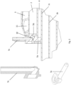
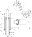
- Fig. 1 shows a cross section of a burner of the invention.
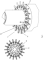
- Fig. 2 shows a cross section of a nozzle construction of the invention.
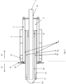
- Fig. 3 shows a burner of the invention with an axial outflow of the secondary air into the hot gas area.
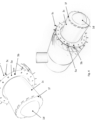
- Fig. 4 shows a three-dimensional view of a burner of the invention.
- Fig. 5 shows an embodiment of the invention with overflow openings and partitions.
- Fig. 6 shows a nozzle construction of an embodiment of the invention.
- Fig. 7 shows another embodiment of the invention with integrated guide vanes on the injector intake nozzles.
- Fig. 8 shows yet another embodiment of the invention with a supply line for additives.
- Fig. 9 shows yet another embodiment of the invention with injector intake pipes for mixing exhaust gas from the combustion chamber into the secondary air flow.
- Fig. 10 shows another embodiment of the invention with an adjustable ring aperture in the primary air supply line.
- Fig. 11 shows a serrated nozzle gap that allows the secondary air to flow out both axially and radially in relation to the longitudinal axis.
- Fig. 12 shows a control concept for regulating the low-NOx burner.
- the secondary air supply line 1a, 1b, 1c is adjustable in length. Approximately 1/3 of the secondary air supply line 1 extends into the hot gas side area 21.
- the ratio of the outer diameter of the innermost pipe 1a of the secondary air supply line : the outer diameter of the middle pipe 1b of the secondary air supply line : the outer diameter of the outermost pipe 1c of the secondary air supply line is approximately 1 : 1.8 : 2.6.
- the second dead volume 9 is approximately 1/5 of the length of the secondary air supply line 1.
- the ratio of the inner diameter of the supply line for fuel 2 : the outer diameter of the supply line for fuel 2 is approximately 1 : 1.4.
- the ratio of the inner diameter of the supply line for primary air 3 : the outer diameter of the supply line for primary air 3 is approximately 1 : 1.3.
- the first dead volume 4 has vacuum or thermal insulation.
- the burner as described in Example 1 is modified as follows: the outermost pipe of the supply line for secondary air 1c has overflow channels 1g, which open into the first dead volume 4, and the first dead volume 4 has partitions 4a, which reduce the first dead volume 4, and the annular orifice 5a is adjustable and has passages 5d on the inside.
- the burner as described in Example 1 or Example 2 has the following modification: the radially aligned injector intake nozzle 5c has at least one guide plate 5e which is aligned in the same way as the swirl plate 11 in the primary air supply line 3.
- the burner as shown in one of the above examples has the following modification: the outermost pipe of the secondary air supply line 1c has a nozzle ring 1h with radially or radially and axially aligned outflow openings at the outlet into the hot gas side region 21.
- the burner as shown in one of the above examples has the following modification: in the dome-shaped closure 1d of the middle pipe of the secondary air supply line 1b, pipe pieces 1i are arranged, which protrude at one end through the dome-shaped closure 1d and at the opposite end through a dust baffle 1j.
- a feed line for additives 2a is arranged centrally along the burner axis and protrudes through the dome-shaped closure of the middle pipe of the feed line for Secondary air 1d, which supply line 2a has a nozzle 2b on the hot gas side area 21.
- secondary air is introduced into the secondary air supply line 1, the secondary air being swirled by the swirl plates 1f; fuel is introduced into the fuel supply line 2, the fuel being injected into the swirled primary air at an outward angle of attack through the holes in the annular orifice 5a; Primary air is introduced into the primary air supply line 3, whereby the primary air is swirled by the swirl plates 11.
- the proportion of secondary air is 40 vol.% and the proportion of primary air is 60 vol.% of the total air required for combustion.
- the total air ratio for the sum of primary and secondary air ⁇ is approximately 1.1.
- the primary air and secondary air is an air-exhaust gas mixture.
- the fuel is natural gas.
- the outwardly directed injector intake nozzles 5c are cooled by the outflowing primary air.
- the quantities of the material flows are controlled based on a rigidly functioning programmed logic for low NOx and CO emissions.
Landscapes
- Engineering & Computer Science (AREA)
- Mechanical Engineering (AREA)
- General Engineering & Computer Science (AREA)
- Chemical & Material Sciences (AREA)
- Combustion & Propulsion (AREA)
Description
- Diese Erfindung betrifft einen Brenner, der ein Abgas mit niedrigem NOx-Gehalt erzeugt, sowie ein Verfahren zur Verbrennung von Brennstoff mit geringem Anteil von NOx im Abgas.
- Stickoxide, chemisch als allgemeine Formel NOx für diverse Stickoxide dargestellt, sind ein umweltschädliches Abgas, für die strenge Grenzwerte bei der Emission bestehen. Stickoxide NOx entstehen bei hohen Verbrennungstemperaturen aus dem Stickstoff N2 der Luft. Diese Grenzwerte gilt es unter allen Umständen einzuhalten. Die NOx-Grenzwerte können entweder auf der Seite des Brenners durch Steuerung der Verbrennung des Brennstoffes und der Luftzufuhr oder auf der Abgasseite durch nachträgliches Entfernen von bei der Verbrennung entstandenem NOx erreicht werden.
- In der Literatur wurden verschiedene Brennertypen beschrieben, die teilweise eine geringe NOx-Konzentration im Abgas erreichen.
-
DE102004059888A1 beschreibt einen Brenner für staubförmige, flüssige und gasförmige Brennstoffe mit einer rohrförmigen Primärluft- und Staubzuführung, die an ihrem vorderen Ende eine Primärluft- und Staubdüse bildet, einer diese umgebenden ringförmigen Sekundärluftzuführung mit einer ringförmigen Sekundärluftdüse, durch die ein Teil der Verbrennungsluft verdrallt einleitbar ist, einem ringförmig außerhalb der Sekundärluftzuführung angeordneten Tertiärluftdüsenring und einem konischen Brennerstein, wobei der konische Brennerstein sich unmittelbar an die Sekundärluftdüse anschließt und als Halbcombustor ausgebildet ist, und der Tertiärluftdüsenring außerhalb der konisch-trichterförmige Öffnung des Brennersteins angeordnet ist und mehrere Einzeldüsen umfasst. -
DE112011103913T5 beschreibt ein mit Brennstoffstaub befeuertes Kesselsystem, bei dem in horizontaler Richtung abwechselnd eine erste Düse, um Brennstoffstaub zu einer Ofenwand eines Ofens herauszuschießen, und eine zweite Düse, um als Luft zur Verbrennung Luft zur Hochtemperaturverbrennung herauszuschießen, angeordnet sind. -
DE3623103A1 beschreibt einen Durchlauf- oder Speicherwasserheizer mit einer von einem atmosphärischen Gasbrenner beheizten Brennkammer, über die ein Wärmeaustausch zum Wasser stattfindet und die unter Zwischenschaltung eines Ventilators mit einer Zuluftzufuhr- und Abgasabfuhrleitung verbunden ist, wobei die Abgasabfuhrleitung über eine Zweigleitung unmittelbar mit der Zuluftleitung verbunden ist. -
DE3832016A1 beschreibt ein Verfahren zur Verbrennung flüssiger oder gasförmiger Brennstoffe, wobei dieser Verbrennung ein aus Brennstoff und Primärluft bestehendes Gemisch sowie Sekundärluft zugeführt wird, wobei der Primärluft ein Anteil der bei der Verbrennung entstehenden Abgase und der Sekundärluft ein Anteil des Brennstoffes beigemischt wird. -
DE4133176A1 beschreibt einen Brenner für flüssige und/oder gasförmige Brennstoffe, welcher in einem Brennergehäuse ein Primärluftrohr mit einer einen Brennstoffaustrittskopf aufweisenden Brennstoffzuführung und koaxial zu dem Primärluftrohr ein Sekundärluftrohr mit einem Sekundärluftauslass an seinem freien Ende hat, wobei das Sekundärluftrohr den Sekundärluftauslass durch einen zur Brennerachse hin sich im Durchmesser verjüngenden Sekundärluftkanal-Reduzierring begrenzt.DE4435640A1 beschreibt ein Verfahren zur Verbrennung von staubförmigem Brennstoff, insbesondere Kohle, mittels eines Brenners mit einem ein Gemisch aus Luft und Brennstoff (Primärluft) führenden Primärluftrohr und einem Mantelluft führenden und das Primärluftrohr umgebenden Mantelluftrohr, bei dem die Primärluft und verdrallte Mantelluft in eine Brennermuffel unter Bildung einer Primärverbrennungszone mit internem Rezirkulationsgebiet austreten, bei dem beim Austritt der Primärluft die Kohlenstaubkonzentration im Randbereich des Primärluftrohrs unter Erzeugung von Wirbeln aufgerissen wird und bei dem verdrallte Stufenluft der Primärflamme zugeführt wird, wobei vor dem Aufreißen der Kohlenstaubkonzentration im Randbereich die Strömungsgeschwindigkeit der Primärluft verändert wird und die Stufenluft in einem die Primärverbrennungszone umgebenden Kranz von Einzelstrahlen eingebracht wird derart, dass der Gesamtstufenluft ein Drall aufgeprägt wird. -
EP2498002B1 beschreibt einen Industriebrenner einer Thermoprozessanlage zur direkten oder indirekten Beheizung eines Ofenraumes, der eine Brennkammer mit wenigstens einer in einem Heizraum mündenden Öffnung, durch die ein Stoffstrom aus der Brennkammer in den Heizraum gelangt, und zumindest eine Wärmetauschvorrichtung aufweist, die aus dem Heizraum in die Wärmetauschvorrichtung gefördertes Abgas durch Wärmeaustausch mit Brennluft abkühlt, wobei die zumindest eine Wärmetauschvorrichtung sich in Axialrichtung zumindest teilweise entlang der Brennkammer erstreckt, wobei eine Wärmedämmung zwischen der Brennkammer und der zumindest einen Wärmetauschvorrichtung angeordnet ist. -
US6652268B1 beschreibt eine Brennerbaugruppe mit einem Gehäuse mit einem Lufteinlass und einem Brennerende. Ein im Gehäuse montiertes Laufrad steht mit dem Lufteinlass in Verbindung und ist dazu geeignet, Luft zum Brennerende des Gehäuses zu leiten. Die Brennerbaugruppe umfasst außerdem ein inneres Luftrohr, das am Brennerende des Gehäuses montiert ist, um eine innere und eine äußere Verbrennungszone zu definieren. Die Baugruppe umfasst außerdem mehrere Strahlungsplatten, die am Brennerende des Gehäuses neben der äußeren Verbrennungszone montiert sind, eine innere Luftwirbelschaufel, die auf dem inneren Luftrohr montiert ist, um einen Teil der Luft vom Laufrad in die innere Verbrennungszone zu leiten, eine innere Gaseinspritzdüse, die auf dem inneren Luftrohr montiert ist, um gasförmigen Brennstoff in die innere Verbrennungszone zu leiten, eine äußere Luftwirbelschaufel, die am Brennerende des Gehäuses montiert ist, um einen Teil der Luft vom Laufrad in die äußere Verbrennungszone zu leiten, und mehrere äußere Gaseinspritzdüsen, die am Brennerende des Gehäuses montiert sind, um gasförmigen Brennstoff in die äußere Verbrennungszone zu leiten. Ein erster Zinnenring ist um den Umfang des inneren Luftrohrs herum montiert, und ein zweiter Zinnenring ist um den Umfang des Brennerendes des Gehäuses herum montiert. -
US5807094A beschreibt einen mit Luft vorgemischten Erdgasbrenner mit verringerten thermischen und sofortigen NOx-Emissionen, der eine zentrale, zylindrische Kernkammer und eine äußere ringförmige Kammer verwendet, die durch einen hohlen Zylinder getrennt sind, der an einem vorderen Ende des Brenners neben einer Brennerkehle eine Vielzahl von Gasdüsen aufweist. Die Vielzahl der Gasdüsen leitet Erdgas in eine Kernkammer ein, wobei der Luftstrom durch einen festen Verwirbler strömt und durch eine verschiebbare Luftstromklappe gesteuert wird, die mit der zentralen, zylindrischen Kernkammer verbunden ist. An einem Auslass der zentralen, zylindrischen Kernkammer wird vorzugsweise ein reduziertes stöchiometrisches Luft-Kraftstoff-Verhältnis (von ungefähr 0,6) aufrechterhalten. Der Rest der Verbrennungsluft wird durch die äußere Ringkammer zugeführt, um ein Gesamt- oder kumulatives stöchiometrisches Brennerverhältnis von etwa 1,05 aufrechtzuerhalten. - Ziel der vorliegenden Erfindung ist, einen Brenner bereitzustellen, der einen geringen NOx-Gehalt im Abgas erzeugt.
- Erfindungsgemäß wird dies dadurch erreicht, indem ein Brenner bereitgestellt wird, der einen Heißgasseitenbereich und einen Außenbereich, eine Zuleitung für Primärluft, eine Zuleitung für Sekundärluft, eine Zuleitung für Brennstoff umfasst, wobei
- die Zuleitung für Sekundärluft drei konzentrisch angeordnete zylindrische Rohre (ein innerstes Rohr, ein mittleres Rohr und ein äußerstes Rohr) umfasst, wobei:
- die Zuleitung für Sekundärluft in den Heißgasseitenbereich hineinragt;
- das innerste Rohr zum Außenbereich hin offen ist und zur Heißgasseite hin offen ist;
- das mittlere Rohr konzentrisch um das innerste Rohr angeordnet ist und einen kuppelförmigen Verschluss aufweist, der das innerste Rohr auf der Heißgasseite kuppelförmig umschließt,
- und zum Außenbereich hin verschlossen ist;
- das mittlere Rohr Überströmkanäle aufweist, die im Außenbereich angeordnet sind, Bohrungen aufweisen und in Richtung des äußersten Rohrs offen sind;
- das äußerste Rohr zum Außenbereich hin verschlossen ist und zur Heißgasseite hin offen ist und verstellbare Drallbleche bei der Öffnung auf der Heißgasseite aufweist, die einen Anstellwinkel von 15° bis 80° aufweisen;
- die Zuleitung für Brennstoff konzentrisch um die Zuleitung für Sekundärluft angeordnet ist, die unmittelbar nach Eintritt in den Heißgasseitenbereich endet;
- wobei ein erstes Totvolumen im Inneren des Brenners zwischen der Zuleitung für Sekundärluft und der Zuleitung für Brennstoff besteht und
- wobei die Zuleitung für Brennstoff auf der Heißgasseite eine Düsenkonstruktion aufweist, die Folgendes umfasst:
- eine Ringblende mit Löchern;
- radial ausgerichtete Injektoransaugdüsen, die in Fluid-Verbindung mit den Löchern stehen und die an der Ansaugseite über den äußeren Durchmesser der Zuleitung für Primärluft hinausragen;
- wobei die Löcher in der Ringblende einen Anstellwinkel aufweisen, der 0° - 60 °, vorzugsweise 10° - 45°, insbesondere 45°, beträgt,
- wobei die Ringblende einen Kegelstumpf ausbildet, der einen Anstellwinkel von 0° - 70°, vorzugsweise 20° - 45°, aufweist,
- wobei die Kegelbasis Richtung Außenbereich zeigt;
- ein zweites Totvolumen zwischen Zuleitung für Sekundärluft und Zuleitung für Brennstoff auf der Seite des Außenbereichs angeordnet ist;
- die Zuleitung für Primärluft konzentrisch um die Zuleitung für Brennstoff angeordnet ist, die unmittelbar nach Eintritt in den Heißgasseitenbereich endet und Folgendes aufweist:
- bei der Öffnung auf der Heißgasseite eine konische Verjüngung des Durchmessers, wobei die konische Verjüngung einen Kegelstumpf ausbildet, der einen Winkel von 0° - 20° aufweist;
- eine verstellbare Ringblende an der der Heißgasseite zugewandten Öffnung der konischen Verjüngung;
- im Anstellwinkel verstellbare Drallbleche, die in einem Winkel von 10° bis 90°, vorzugsweise 40° - 70°, angeordnet sind.
- Durch diesen Aufbau eines Brenners wird eine effektive Verbrennung des Brennstoffs mit einem geringen NOx-Gehalt im Abgas erreicht. Die Sekundärluft wird im kuppelförmigen Verschluss, der sich auf der Heißgasseite befindet, vorgewärmt und tritt vorgewärmt in den Brennraum ein. Die Drallbleche im äußersten Rohr der Zuleitung für Sekundärluft bewirken eine gleichmäßige Verteilung der Sekundärluft um den Umfang des äußersten Rohrs, sodass über den gesamten Umfang der Öffnung ein gleichmäßiger Sekundärluftstrom in den Brennraum (d. h. in die Heißgasseite) eintritt. Zusätzlich dazu wird durch die Drallbleche eine Vortexströmung erzwungen, die die Flamme stabilisiert.
- Die "Zuleitung für Primärluft" kann auch "Primärluft-Zuleitung", die "Zuleitung für Sekundärluft" kann auch "Sekundärluft-Zuleitung" und die "Zuleitung für Brennstoff" auch "BrennstoffZuleitung" genannt werden.
- Das äußerste Rohr der Zuleitung für Sekundärluft und/oder der kuppelförmige Verschluss des mittleren Rohrs der Zuleitung für Sekundärluft können hitzebeständig beschichtet sein oder aus hitzebeständigem Material ausgebildet sein, z.B. Keramik.
- Die Düsenkonstruktion in der Zuleitung für Brennstoff bewirkt eine gleichmäßige Verteilung des Brennstoffs über den gesamten Umfang der Zuleitung für Brennstoff. Die Düsenkonstruktion besteht aus einer Ringblende mit Löchern, über die der Brennstoff in den Brennraum geleitet wird, und Injektoransaugdüsen zur Ansaugung von Abgas aus der näheren Umgebung, die in dieser Ringblende eingebaut sind. Dabei sind die Injektoransaugdüsen entlang der Strömungskanäle für den Brennstoff platziert. Die Injektoren verfügen ansaugseitig über röhrenförmige, längliche Ansaugdüsen. Die Länge der Injektoransaugdüsen ist an der Ansaugseite länger als die Dicke der Zuleitung für Primärluft, d.h. die Injektoransaugdüsen können Abgas aus dem näheren Umfeld des Brenners direkt in den gasförmigen Brennstoffstrom einsaugen. Alternativ dazu sind die Ansaugöffnungen der Injektoransaugdüsen nach innen gerichtet und stehen in Fluid-Verbindung mit dem Abgasvolumen, das die Sekundärluftdüse umgibt. Die Ausführungsform der Abgasansaugung von innen oder von außen richtet sich nach den baulichen Gegebenheiten der zu befeuernden Thermoprozessanlage, wobei die Ausführungsform mit der Absaugung von außen den Vorteil bietet, dass das angesaugte Abgas in den Ansaugrohren der Injektoren durch die ausströmende Primärluft gekühlt wird. Der angesaugte und gekühlte Abgasstrom wird in den Brennstoffstrom eingebracht. Dadurch erhält man am Austritt der Brennstoffdüsen ein Brennstoff-Abgas-Gemisch, das in einer Verbrennungsreaktion mit Sauerstoff umgesetzt wird. Der Abgasanteil im Brennstoffstrom wirkt NOx-mindernd, da die Spitzentemperatur in der Flamme niedrig bleibt, wodurch weniger thermisches NOx entsteht.
- Das erste Totvolumen dient zur Wärmeisolation und kann mit einem geeigneten Material zur thermischen Isolation zwischen den Bereichen Sekundärluft und Brennstoff ausgefüllt sein.
- Die konische Verjüngung in der Zuleitung für Primärluft dient der Beschleunigung des Primärluftstroms. Die verstellbare Ringblende und die im Anstellwinkel verstellbaren Drallbleche dienen der gleichmäßigen Verteilung der Primärluft über den gesamten Umfang der Zuleitung bzw. zur Erzeugung einer Vortexstruktur im abströmenden Fluid.
- Außerdem wird durch diese Anordnung der Sekundärluftstrom örtlich in der Längsachse versetzt der Verbrennungsreaktion mit dem Brennstoff zugeführt. Mit diesem Anordnungskonzept wird eine gestufte Verbrennung auf Basis einer Luftstufung realisiert.
- Ein Brenner kann einen Leistungsbereich von 10 kWh bis 100 000 kWh abdecken, was einem stündlichen Erdgasverbrauch von 1 m3 bis 10.000 m3 entspricht. Der Brenner kann mit einem beliebigen gasförmigen Brennstoff betrieben werden, wie beispielsweise Erdgas, Methan, Ethan, Propan, Butan usw., sowie auch mit staubförmigen festen Brennstoffen, wie beispielsweise Kohlenstaub, oder vergasten flüssigen Brennstoffen, wie beispielsweise Hydrazin.
- In einer Ausführungsform der Erfindung kann die Zuleitung für Sekundärluft in der Länge verschiebbar sein, wobei das Rohr-in-Rohr-System zur Zuleitung der Sekundärluft mit einer Länge L in den Brennraum hineinragt, wobei die Länge L entsprechend der Beziehung L = D * f mit D = Außendurchmesser der Primärluftzuleitung und f = 0 ≤ f ≤ 3 variiert werden kann. Dadurch kann die Konstruktion den Strömungsgeschwindigkeiten der Gase (Primärluft, Sekundärluft, Brennstoff) und die Anforderungen der Verbrennung angepasst werden. Insbesondere das Konzept der Luftstufung zur NOx-Reduktion kann hiermit variabel gestaltet werden und in Hinblick einer möglichst hohen NOx-Reduktion optimiert werden.
- In einer Ausführungsform der Erfindung kann etwa 1/3 der Zuleitung für Sekundärluft in den Heißgasseitenbereich hineinragen. Dadurch wird eine gute Wärmeübertragung auf die Sekundärluft gewährleistet. Durch die Vorwärmung der Sekundärluft wird ein stabilerer und vollständiger Ausbrand des restlichen Brennstoffes sichergestellt.
- In einer anderen Ausführungsform der Erfindung kann das Verhältnis von (Außendurchmesser von innerstem Rohr der Zuleitung für Sekundärluft) (im Folgenden: ADi) : (Außendurchmesser von mittlerem Rohr der Zuleitung für Sekundärluft) (im Folgenden: ADm) : (Außendurchmesser von äußerstem Rohr der Zuleitung für Sekundärluft) (im Folgenden: ADa) etwa 0,7-1,3 : 1,26-2,34 : 1,82-3,38, vorzugsweise etwa 1 : 1,8 : 2,6, betragen. Dies stellt eine hervorragende Geometrie dar, die ein verbessertes Verbrennungsergebnis liefert.
- In einer Ausführungsform der Erfindung kann das zweite Totvolumen etwa 1/5 der Länge der Zuleitung für Sekundärluft betragen. Dies dient zur thermischen Isolation zwischen Sekundärluftbereich und Brennstoffzuleitung.
- In einer Ausführungsform der Erfindung kann das Verhältnis von (Innendurchmesser der Zuleitung für Brennstoff) (im Folgenden: IDZ) : (Außendurchmesser der Zuleitung für Brennstoff) im Folgenden: ADZ) etwa 0,7-1,3 : 0,98-1,82, vorzugsweise etwa 1 : 1,4, betragen. Dies stellt eine hervorragende Geometrie dar, die ein verbessertes Verbrennungsergebnis liefert.
- In einer Ausführungsform der Erfindung kann das Verhältnis von (Innendurchmesser der Zuleitung für Primärluft) (im Folgenden: IDP) : (Außendurchmesser der Zuleitung für Primärluft) (im Folgenden: ADP) etwa 0,7-1,3 : 0,91-1,69, vorzugsweise etwa 1 : 1,3, betragen. Dies stellt eine hervorragende Geometrie dar, die ein verbessertes Verbrennungsergebnis liefert.
- In einer Ausführungsform der Erfindung kann das erste Totvolumen Vakuum oder eine thermische Isolierung aufweisen. Dies stellt sicher, dass sich der Brennstoff nicht vor dem Eintritt in die Heißgasseite erwärmt.
- In einer Ausführungsform der Erfindung kann das äußerste Rohr der Zuleitung für Sekundärluft Überströmkanäle aufweisen, die in das erste Totvolumen münden, und das erste Totvolumen Abschottungen aufweisen, die das erste Totvolumen verkleinern, und die Ringblende verstellbar sein und Durchlässe an der Innenseite aufweisen. Dadurch entsteht ein Tertiärluftstrom, der in den Heißgasseitenbereich über eine verstellbare Ringblende an der Innenseite der Brennstoffdüse strömt. Dadurch wird eine effizientere und stabilere Verbrennung erreicht.
- In einer Ausführungsform der Erfindung kann die radial ausgerichtete Injektoransaugdüse zumindest ein Leitblech aufweisen, das gleich ausgerichtet ist wie das Drallblech in der Zuleitung für Primärluft. Dies verleiht der Primärluft einen zusätzlichen Drall. Die Ausbildung einer Vortexströmung der Primärluft wird dadurch zusätzlich unterstützt.
- In einer Ausführungsform der Erfindung kann das äußerste Rohr der Zuleitung für Sekundärluft einen Düsenring mit radial oder radial und axial ausgerichteten Ausströmungsöffnungen beim Auslass in den Heißgasseitenbereich aufweisen.
- In einer Ausführungsform der Erfindung können in dem kuppelförmigen Verschluss des mittleren Rohrs der Zuleitung für Sekundärluft Rohrstücke angeordnet sein, die an einem Ende durch den kuppelförmigen Verschluss ragen und am gegenüberliegenden Ende durch eine Staublende ragen. Durch die rückströmende Sekundärluft wird mittels Injektorwirkung Abgas aus dem Brennraum "mitgenommen" und mit der Sekundärluft vermischt. Dieses Gasgemisch wird mit dem Brennstoff bei den Ausströmungsöffnungen der Zuleitung für Sekundärluft verbrannt. Die Staublende verursacht den für die Injektorwirkung notwendigen Staudruck und den damit verbundenen abströmseitigen Druckabfall.
- In einer Ausführungsform der Erfindung weist der Querschnitt der erdgasführenden Ringblende einen nach außen gerichteten Konus auf, über den die Primärluft strömt. Mit dieser Geometrie der Ringblende wird eine nach innen gerichtete Strömung der Primärluft erzwungen. Zusätzlich dazu kann zur besseren Ausrichtung der Primärluftströmung auf dem Konus eine zylindrische Ringblende aufgesetzt sein.
- In einer Ausführungsform der Erfindung können auf der Ringblende auf der Innenseite Löcher angeordnet sein, die in Fluid-Verbindung mit den Löchern in der Ringblende stehen. Dadurch wird Abgas von der Innenseite über die Injektoransaugdüse in den Brennstoffstrom eingesaugt.
- In einer Ausführungsform kann eine Zuleitung für Zusatzstoffe zentral entlang der Brennerachse angeordnet sein und durch den kuppelförmigen Verschluss des mittleren Rohrs der Zuleitung für Sekundärluft ragen, welche Zuleitung auf dem Heißgasseitenbereich eine Düse aufweist. Die Zuleitung kann auch radial um den Brenner herum angeordnet sein. Durch diese Zuleitung können brennbare oder nicht brennbare Zusatzstoffe, wie Altöle und Heizöle, fetthaltige Lösungen tierischen oder pflanzlichen Ursprungs, organische Abfallstoffe und Lösemittel, Abfallsäuren und Laugen, Abwässer, schwefelhaltige Flüssigkeiten, chlorierte und halogenierte Gase und Flüssigkeiten über dieses zusätzliche Einspritzsystem mitverbrannt werden. Die genannten Stoffe werden mittels der zusätzlichen Zuleitung, die zentral entlang der Brennerachse oder radial um den Brenner herum angeordnet sind, dem Brennraum zugeführt. Über eine Düse werden die Zusatzstoffe fein zerstäubt in die Flamme des Brenners eingedüst. Durch diese Zuleitung kann auch Abgas im Gegenstrom zur Sekundärluft nach außen abgezogen werden, wodurch der Sekundärluftstrom vorgewärmt wird.
- In einer Ausführungsform können die Ausströmöffnungen der Rohrstücke an der Seite der Staublenden durch einen in der Längsrichtung verstellbaren Kegel (Ventil) verengbar sein. Dadurch kann der Gesamtabgasmassenstrom in dem Sekundärluftstrom geregelt werden.
- In einer Ausführungsform kann ein äußerer Ringspalt durch zwei Rohre, die den Brenner außen umgeben, ausgebildet sein, wobei das innere der beiden Rohre eine Öffnung aufweist und das äußere der beiden Rohre einen Ausgang aufweist. Über den äußeren Ringspalt kann Abgas im Gegenstrom zur Primärluft über den Ausgang, der im äußeren der beiden Rohre angeordnet ist, nach außen abgezogen werden, wodurch der Primärluftstrom vorgewärmt wird. Zusätzlich dazu wird durch das Innere der beiden Rohre ein abgeschlossener Brennraum geschaffen, in dem die gestufte Verbrennung stattfindet und die Heißgase über die Öffnung, die am Inneren der beiden Rohre angeordnet ist, ausströmen können.
- Ein anderer Aspekt der Erfindung betrifft ein Verfahren zur Verbrennung von Brennstoff in einem wie oben definierten Brenner, wobei in einen wie oben definierten Brenner Sekundärluft in die Zuleitung für Sekundärluft eingeleitet wird, wobei durch die Drallbleche die Sekundärluft verdrallt wird; Brennstoff in die Zuleitung für Brennstoff eingeleitet wird, wobei durch die Löcher in der Ringblende der Brennstoff in einem nach außen gerichteten Anstellwinkel in die verdrallte Primärluft eingedüst wird; Primärluft in die Zuleitung für Primärluft eingeleitet wird, wobei durch die Drallbleche die Primärluft verdrallt wird. Dadurch wird eine effiziente Verbrennung mit niedrigem NOx-Gehalt im Abgas erreicht.
- In einer Ausführung des anderen Aspekts der Erfindung kann der Anteil an Sekundärluft 20-50 Vol.-% und der Anteil an Primärluft 50-80 Vol.-% der gesamten, für die Verbrennung notwendigen Luft betragen. Dieses Aufteilungsverhältnis ergibt ein hervorragendes Abgasverhalten.
- In einer Ausführung des anderen Aspekts der Erfindung kann die Gesamtluftzahl für die Summe aus Primär- und Sekundärluft λ etwa 1,0 bis 2,0, vorzugsweise etwa 1,0 bis 1,5, insbesondere etwa 1,0 bis 1,1, betragen. So kann ein stöchiometrischer Überschuss an Luft bzw. Sauerstoff verwendet werden.
- In einer Ausführung des anderen Aspekts der Erfindung kann die Sauerstoffkonzentration in der Sekundärluft und Primärluft von 21 Vol.-% bis 100 Vol.-% betragen. Dementsprechend weist der Stickstoffgehalt mit steigenden Sauerstoffkonzentrationen niedrigere Konzentrationen auf. Durch höhere Sauerstoffkonzentrationen können Verbrennungsprozesse wesentlich effizienter geführt werden, da die Verbrennungstemperatur und der Wärmeübergang auf Basis der Gasstrahlung mit steigenden Sauerstoffkonzentrationen im Oxidatorstrom deutlich ansteigen. Somit lässt sich mit diesem Brenner eine Steigerung der Energieeffizienz bei gleichzeitig niedrigen NOx-Emissionen erzielen.
- In einer Ausbildung des Verfahrens kann die Primärluft und Sekundärluft ein Luft-Abgas-Gemisch, ein Luft-Sauerstoff-Gemisch oder ein Abgas-Sauerstoff-Gemisch sein. Somit lässt sich mit dem vorliegenden Brenner ein Verfahren der externen Abgaszirkulation mit Sauerstoffanreicherung realisieren. Dabei wird ein Abgasteilstrom aus dem Hauptstrom abgezweigt, mit Sauerstoff angereichert und dem Brenner an den Eingängen für Primär- und Sekundärluft als Luftersatz zugeführt. Die Enthalpie des rückgeführten Abgas-Sauerstoff-Massenstromes kann dann für die Energieeinsparung direkt verwendet werden. Auf Basis dieses Konzeptes lassen sich nicht nur NOx-, sondern auch CO2-Emissionen drastisch reduzieren.
- In einer Ausführung des anderen Aspekts der Erfindung kann der Brennstoff Stickstoff umfassen. Es können stickstoffhältige Brennstoffe wie beispielsweise Hydrazin verwendet werden. Ebenfalls können Kohlenwasserstoffe, die als Brennstoffe eingesetzt werden, geringe Mengen an Stickstoff enthalten. Mit diesem Brenner können diese mit Stickstoff belasteten Brennstoffe ohne nennenswerte NOx-Emissionen zu verursachen verbrannt werden.
- In einer Ausführungsform kann der Brennstoff gasförmige Kohlenwasserstoffe, Wasserstoff, Biogase, Kohlenstaub-LuftGemische, Schwefelwasserstoffe, Kohlenmonoxidgas, Kohlenmonoxid-Wasserstoff-Gemische, Kokereigase, Tailgase umfassen bzw. sein.
- In einer Ausbildung des Verfahrens kann Abgas direkt in den Brennstoffstrom durch die Injektorwirkung eingesaugt werden. Dadurch wird eine effizientere NOx-Reduktion erzielt.
- In einer Ausbildung des Verfahrens können die nach außen gerichteten Injektoransaugdüsen durch die ausströmende Primärluft gekühlt werden. Die thermische Belastung der Injektoransaugdüsen wird dadurch minimiert.
- In einer Ausbildung des Verfahrens kann der angesaugte Abgasstrom im Inneren der Injektoransaugdüsen unter die Kondensationstemperatur (Taupunkt) für die Abgasfeuchte gekühlt werden, wobei Wasser im Abgasstrom auskondensiert und das flüssige Wasser in den Brennstoffstrom eingebracht wird. Dadurch wird ebenfalls eine geringere Verbrennungstemperatur erreicht, wodurch die thermische NOx-Bildung unterdrückt wird.
- In einer Ausbildung des Verfahrens kann Abgas in den Sekundärluftstrom eingesaugt werden und in der Folge ein Luft-Abgas-Gemisch an der Düsenöffnung der Sekundärluft zur Verbrennung mit dem eingedüsten Brennstoff gebracht werden. Das eingebrachte Abgas reduziert die Verbrennungstemperatur und damit die NOx-Emissionen.
- In einer Ausbildung des Verfahrens können die Mengen der Stoffströme auf Basis einer starr funktionierenden programmierten Logik oder eines für die jeweiligen Prozessbedingungen individuell antrainierten neuronalen Netzes automatisch für niedrige NOx- und CO-Emissionen gesteuert werden. So können die gesetzlichen Grenzwerte einfach eingehalten werden.
- In den Beispielen und den Figuren werden folgende Bezugszeichen verwendet:
- 1
- Zuleitung für Sekundärluft
- 1a
- innerstes Rohr der Zuleitung für Sekundärluft
- 1b
- mittleres Rohr der Zuleitung für Sekundärluft
- 1c
- äußerstes Rohr der Zuleitung für Sekundärluft
- 1d
- kuppelförmiger Verschluss des mittleren Rohrs der Zuleitung für Sekundärluft
- 1e
- Überströmkanäle des mittleren Rohrs der Zuleitung für Sekundärluft
- 1f
- Drallbleche für axiale oder radiale Verdrallung der Sekundärluft
- 1g
- Überströmkanal zum ersten Totvolumen
- 1h
- Düsenring mit radialen oder radial und axial ausgerichteten Ausströmungsöffnungen
- 1i
- Injektoransaugrohre zur Einmischung von Abgas aus dem Brennraum in den Sekundärluftstrom
- 1j
- Staublende zur Querschnittsverjüngung in der Rückleitung der Sekundärluft für Injektorsystem zur Einmischung von Abgas in die Sekundärluft
- 1k
- äußerer Ringspalt, der durch Rohre 1m und 1n gebildet ist
- 1l
- Ausgang am äußeren der beiden Rohre 1n, die den äußeren Ringspalt 1k bilden
- 1m
- das innere der beiden Rohre, die den äußeren Ringspalt 1k bilden
- 1n
- das äußere der beiden Rohre, die den äußeren Ringspalt 1k bilden
- 1o
- Öffnung am inneren der beiden Rohre 1m, die den äußeren Ringspalt 1k bilden
- 2
- Zuleitung für Brennstoff
- 2a
- Zuleitung für Zusatzstoffe
- 2b
- Düse auf der Zuleitung für Zusatzstoffe
- 3
- Zuleitung für Primärluft
- 4
- erstes Totvolumen
- 4a
- Abschottung
- 5
- Düsenkonstruktion in der Zuleitung für Brennstoff
- 5a
- Ringblende mit Löchern
- 5b
- Löcher in der Ringblende für Brennstoffzuführung
- 5c
- Injektoransaugdüsen mit radial nach außen oder nach innen gerichtete Ansaugdüsen
- 5d
- Durchlass für Tertiärluft in der Ringblende
- 5e
- integrierte Leitbleche auf den Injektoransaugdüsen
- 5f
- Löcher auf der Innenseite der Ringblende zur Abgasansaugung
- 9
- zweites Totvolumen
- 10
- verstellbare Ringblende in der Zuleitung für Primärluft
- 11
- Drallbleche in der Zuleitung für Primärluft
- 21
- Heißgasseitenbereich
- 22
- Außenbereich
-
Fig. 1 zeigt einen Querschnitt eines Brenners der Erfindung. -
Fig. 2 zeigt einen Querschnitt einer Düsenkonstruktion der Erfindung. -
Fig. 3 zeigt einen Brenner der Erfindung mit einer axialen Ausströmung der Sekundärluft in den Heißgasbereich. -
Fig. 4 zeigt eine dreidimensionale Ansicht eines Brenners der Erfindung. -
Fig. 5 zeigt eine Ausführungsform der Erfindung mit Überströmöffnungen und Abschottungen. -
Fig. 6 zeigt eine Düsenkonstruktion einer Ausführungsform der Erfindung. -
Fig. 7 zeigt eine andere Ausführungsform der Erfindung mit integrierten Leitblechen auf den Injektoransaugdüsen. -
Fig. 8 zeigt eine wieder andere Ausführungsform der Erfindung mit einer Zuleitung für Zusatzstoffe. -
Fig. 9 zeigt noch ein andere Ausführungsform der Erfindung mit Injektoransaugrohren zur Einmischung von Abgas aus dem Brennraum in den Sekundärluftstrom. -
Fig. 10 zeigt wieder eine andere Ausführungsform der Erfindung mit einer verstellbaren Ringblende in der Zuleitung für Primärluft. -
Fig. 11 zeigt einen gezackten Düsenspalt, der die Sekundärluft sowohl axial als auch radial in Relation zur Längsachse ausströmen lässt. -
Fig. 12 zeigt ein Steuerungskonzept zur Regelung des Low-NOx-Brenners. - Ein erfindungsgemäßer Brenner umfasst einen Heißgasseitenbereich 21 und einen Außenbereich 22, eine Zuleitung für Primärluft 3, eine Zuleitung für Sekundärluft 1, eine Zuleitung für Brennstoff 2, wobei
- die Zuleitung für Sekundärluft 1 drei konzentrisch angeordnete zylindrische Rohre ein innerstes Rohr 1a, ein mittleres Rohr 1b und ein äußerstes Rohr 1c umfasst, wobei:
- die Zuleitung für Sekundärluft 1 in den Heißgasseitenbereich 21 hineinragt;
- das innerste Rohr 1a zum Außenbereich 22 hin offen ist und zur Heißgasseite 21 hin offen ist;
- das mittlere Rohr 1b konzentrisch um das innerste Rohr 1a angeordnet ist und einen kuppelförmigen Verschluss 1d aufweist, der das innerste Rohr 1a auf der Heißgasseite 21 kuppelförmig umschließt, und zum Außenbereich 22 hin verschlossen ist;
- das mittlere Rohr 1b Überströmkanäle 1e aufweist, die im Außenbereich 22 angeordnet sind, Bohrungen aufweisen und in Richtung des äußersten Rohrs 1c offen sind;
- das äußerste Rohr 1c zum Außenbereich 22 hin verschlossen ist und zur Heißgasseite 21 hin offen ist und verstellbare Drallbleche 1f bei der Öffnung auf der Heißgasseite 21 aufweist, die einen Anstellwinkel von 40° aufweisen;
- die Zuleitung für Brennstoff 2 konzentrisch um die Zuleitung für Sekundärluft 1 angeordnet ist, die unmittelbar nach Eintritt in den Heißgasseitenbereich 21 endet;
- wobei ein erstes Totvolumen 4 im Inneren des Brenners zwischen der Zuleitung für Sekundärluft 1 und der Zuleitung für Brennstoff 2 besteht und
- wobei die Zuleitung für Brennstoff 2 auf der Heißgasseite 21 eine Düsenkonstruktion 5 aufweist, die Folgendes umfasst:
- eine Ringblende 5a mit Löchern 5b ;
- radial ausgerichtete Injektoransaugdüsen 5c, die in Fluid-Verbindung mit den Löchern 5b stehen und die an der Ansaugseite über den äußeren Durchmesser der Zuleitung für Primärluft 3 hinausragen;
- wobei die Löcher 5b in der Ringblende 5a einen Anstellwinkel aufweisen, der 45° beträgt,
- wobei die Ringblende 5a einen Kegelstumpf ausbildet, der einen Anstellwinkel von 30° aufweist, wobei die Kegelbasis Richtung Außenbereich 22 zeigt;
- ein zweites Totvolumen 9 zwischen Zuleitung für Sekundärluft 1 und Zuleitung für Brennstoff 2 auf der Seite des Außenbereichs 22 angeordnet ist;
- die Zuleitung für Primärluft 3 konzentrisch um die Zuleitung für Brennstoff 2 angeordnet ist, die unmittelbar nach Eintritt in den Heißgasseitenbereich 21 endet und Folgendes aufweist:
- bei der Öffnung auf der Heißgasseite 21 eine konische Verjüngung des Durchmessers, wobei die konische Verjüngung einen Kegelstumpf ausbildet, der einen Winkel von 10° aufweist;
- eine verstellbare Ringblende 10 an der der Heißgasseite 21 zugewandten Öffnung der konischen Verjüngung;
- im Anstellwinkel verstellbare Drallbleche 11, die in einem Winkel von 55° angeordnet sind.
- Die Zuleitung für Sekundärluft 1a, 1b, 1c ist in der Länge verschiebbar. Etwa 1/3 der Zuleitung für Sekundärluft 1 ragt in den Heißgasseitenbereich 21 hinein.
- Das Verhältnis von Außendurchmesser von innerstem Rohr 1a der Zuleitung für Sekundärluft : Außendurchmesser von mittlerem Rohr 1b der Zuleitung für Sekundärluft : Außendurchmesser von äußerstem Rohr 1c der Zuleitung für Sekundärluft beträgt etwa 1 : 1,8 : 2,6.
- Das zweite Totvolumen 9 beträgt etwa 1/5 der Länge der Zuleitung für Sekundärluft 1.
- Das Verhältnis von Innendurchmesser der Zuleitung für Brennstoff 2 : Außendurchmesser der Zuleitung für Brennstoff 2 beträgt etwa 1 : 1,4.
- Das Verhältnis von Innendurchmesser der Zuleitung für Primärluft 3 : Außendurchmesser der Zuleitung für Primärluft 3 beträgt etwa 1 : 1,3.
- Das erste Totvolumen 4 weist Vakuum oder eine thermische Isolierung auf.
- Der Brenner wie in Beispiel 1 beschrieben ist wie folgt modifiziert: das äußerste Rohr der Zuleitung für Sekundärluft 1c weist Überströmkanäle 1g auf, die in das erste Totvolumen 4 münden, und das erste Totvolumen 4 weist Abschottungen 4a auf, die das erste Totvolumen 4 verkleinern, und die Ringblende 5a ist verstellbar und weist Durchlässe 5d an der Innenseite auf.
- Der Brenner wie in Beispiel 1 oder Beispiel 2 beschrieben weist folgende Modifikation auf: die radial ausgerichtete Injektoransaugdüse 5c weist zumindest ein Leitblech 5e auf, das gleich ausgerichtet ist wie das Drallblech 11 in der Zuleitung für Primärluft 3.
- Der Brenner wie in einem der obigen Beispiele angeführt weist folgende Modifikation auf: das äußerste Rohr der Zuleitung für Sekundärluft 1c weist einen Düsenring 1h mit radial oder radial und axial ausgerichteten Ausströmungsöffnungen beim Auslass in den Heißgasseitenbereich 21 auf.
- Der Brenner wie in einem der obigen Beispiele angeführt weist folgende Modifikation auf: in dem kuppelförmigen Verschluss 1d des mittleren Rohrs der Zuleitung für Sekundärluft 1b sind Rohrstücke 1i angeordnet, die an einem Ende durch den kuppelförmigen Verschluss 1d ragen und am gegenüberliegenden Ende durch eine Staublende 1j ragen.
- Der Brenner wie in einem der obigen Beispiele angeführt weist folgende Modifikation auf: eine Zuleitung für Zusatzstoffe 2a ist zentral entlang der Brennerachse angeordnet und ragt durch den kuppelförmigen Verschluss des mittleren Rohrs der Zuleitung für Sekundärluft 1d, welche Zuleitung 2a auf dem Heißgasseitenbereich 21 eine Düse 2b aufweist.
- In einen Brenner wie in einem der Beispiel 1 bis 6 beschrieben wird Sekundärluft in die Zuleitung für Sekundärluft 1 eingeleitet, wobei durch die Drallbleche 1f die Sekundärluft verdrallt wird; Brennstoff in die Zuleitung für Brennstoff 2 eingeleitet, wobei durch die Löcher in der Ringblende 5a der Brennstoff in einem nach außen gerichteten Anstellwinkel in die verdrallte Primärluft eingedüst wird;
Primärluft in die Zuleitung für Primärluft 3 eingeleitet, wobei durch die Drallbleche 11 die Primärluft verdrallt wird. - Der Anteil an Sekundärluft beträgt 40 Vol.-% und der Anteil an Primärluft 60 Vol.-% der gesamten, für die Verbrennung notwendigen Luft.
- Die Gesamtluftzahl für die Summe aus Primär- und Sekundärluft λ beträgt etwa 1,1.
- Die Primärluft und Sekundärluft ist ein Luft-Abgas-Gemisch.
- Der Brennstoff ist Erdgas.
- Abgas wird direkt in den Brennstoffstrom durch die Injektorwirkung eingesaugt.
- Die nach außen gerichteten Injektoransaugdüsen 5c werden durch die ausströmende Primärluft gekühlt.
- Die Mengen der Stoffströme werden auf Basis einer starr funktionierenden programmierten Logik für niedrige NOx- und CO-Emissionen gesteuert.
Claims (18)
- Brenner, umfassend einen Heißgasseitenbereich (21) und einen Außenbereich (22), eine Zuleitung für Primärluft (3), eine Zuleitung für Sekundärluft (1), eine Zuleitung für Brennstoff (2),wobei die Zuleitung für Sekundärluft (1) drei konzentrisch angeordnete zylindrische Rohre (ein innerstes Rohr (1a), ein mittleres Rohr (1b) und ein äußerstes Rohr (1c)) umfasst, wobei:die Zuleitung für Sekundärluft (1) in den Heißgasseitenbereich (21) hineinragt;das innerste Rohr (1a) zum Außenbereich (22) hin offen ist und zur Heißgasseite (21) hin offen ist;das mittlere Rohr (1b) konzentrisch um das innerste Rohr (1a) angeordnet ist und einen kuppelförmigen Verschluss (1d) aufweist, der das innerste Rohr (1a) auf der Heißgasseite (21) kuppelförmig umschließt, und zum Außenbereich (22) hin verschlossen ist;das mittlere Rohr (1b) Überströmkanäle (1e) aufweist, die im Außenbereich (22) angeordnet sind, Bohrungen aufweisen und in Richtung des äußersten Rohrs (1c) offen sind;das äußerste Rohr (1c) zum Außenbereich (22) hin verschlossen ist und zur Heißgasseite (21) hin offen ist und verstellbare Drallbleche (1f) bei der Öffnung auf der Heißgasseite (21) aufweist, die einen Anstellwinkel von 15° bis 80° aufweisen;wobei gegebenenfalls in dem kuppelförmigen Verschluss (1d) des mittleren Rohrs der Zuleitung für Sekundärluft (1b) Rohrstücke (1i) angeordnet sind, die an einem Ende durch den kuppelförmigen Verschluss (1d) ragen und am gegenüberliegenden Ende durch eine Staublende (1j) ragen;die Zuleitung für Brennstoff (2) konzentrisch um die Zuleitung für Sekundärluft (1) angeordnet ist, die unmittelbar nach Eintritt in den Heißgasseitenbereich (21) endet;wobei ein erstes Totvolumen (4) im Inneren des Brenners zwischen der Zuleitung für Sekundärluft (1) und der Zuleitung für Brennstoff (2) besteht undwobei die Zuleitung für Brennstoff (2) auf der Heißgasseite (21) eine Düsenkonstruktion (5) aufweist, die Folgendes umfasst:eine Ringblende (5a) mit Löchern (5b);radial ausgerichtete Injektoransaugdüsen (5c), die in Fluid-Verbindung mit den Löchern (5b) stehen und die an der Ansaugseite über den äußeren Durchmesser der Zuleitung für Primärluft (3) hinausragen;wobei die Löcher (5b) in der Ringblende (5a) einen Anstellwinkel aufweisen, der 0° - 60 °, vorzugsweise 10° - 45°, insbesondere 45°, beträgt,wobei die Ringblende (5a) einen Kegelstumpf ausbildet, der einen Anstellwinkel von 0° - 70°, vorzugsweise 20° - 45°, aufweist, wobei die Kegelbasis Richtung Außenbereich (22) zeigt;ein zweites Totvolumen (9) zwischen Zuleitung für Sekundärluft (1) und Zuleitung für Brennstoff (2) auf der Seite des Außenbereichs (22) angeordnet ist;die Zuleitung für Primärluft (3) konzentrisch um die Zuleitung für Brennstoff (2) angeordnet ist, die unmittelbar nach Eintritt in den Heißgasseitenbereich (21) endet und Folgendes aufweist:bei der Öffnung auf der Heißgasseite (21) eine konische Verjüngung des Durchmessers, wobei die konische Verjüngung einen Kegelstumpf ausbildet, der einen Winkel von 0° - 20° aufweist;eine verstellbare Ringblende (10) an der der Heißgasseite (21) zugewandten Öffnung der konischen Verjüngung;im Anstellwinkel verstellbare Drallbleche (11), die in einem Winkel von 10° bis 90°, vorzugsweise 40° - 70°, angeordnet sind.
- Brenner nach Anspruch 1, wobei A die Zuleitung für Sekundärluft (1a, 1b, 1c) in der Länge verschiebbar ist, wobei das Rohr-in-Rohr-System zur Zuleitung der Sekundärluft mit einer Länge L in den Brennraum hineinragt, wobei die Länge L entsprechend der Beziehung L = D * f mit D = Außendurchmesser der Primärluftzuleitung und f einen Wert von 0 ≤ f ≤ 3 annehmen kann, oder etwa 1/3 der Zuleitung für Sekundärluft (1) in den Heißgasseitenbereich (21) hineinragt.
- Brenner nach einem der Ansprüche 1 oder 2,wobei das Verhältnis von ADi : ADm : ADa etwa 0,7-1,3 : 1,26-2,34 : 1,82-3,38, vorzugsweise etwa 1 : 1,8 : 2,6, beträgt,wobei ADi für den Außendurchmesser des innersten Rohrs der Zuleitung für Sekundärluft (1a) steht,ADm für den Außendurchmesser des mittleren Rohrs der Zuleitung für Sekundärluft (1b) steht undADa für den Außendurchmesser des äußersten Rohrs der Zuleitung für Sekundärluft (1c) steht.
- Brenner nach einem der vorangegangenen Ansprüche,wobei das Verhältnis von IDZ : ADZ etwa 0,7-1,3 : 0,98-1,82, vorzugsweise etwa 1 : 1,4, beträgt,wobei IDZ für den Innendurchmesser der Zuleitung für Brennstoff (2) steht undADZ für den Außendurchmesser der Zuleitung für Brennstoff (2) steht.
- Brenner nach einem der vorangegangenen Ansprüche,wobei das Verhältnis von IDP : ADP etwa 0,7-1,3 : 0,91-1,69, vorzugsweise etwa 1 : 1,3, beträgt,wobei IDP für den Innendurchmesser der Zuleitung für Primärluft (3) steht undADP für den Außendurchmesser der Zuleitung für Primärluft (3) steht.
- Brenner nach einem der vorangegangenen Ansprüche,wobei das äußerste Rohr der Zuleitung für Sekundärluft (1c) Überströmkanäle (1g) aufweist, die in das erste Totvolumen (4) münden, unddas erste Totvolumen (4) Abschottungen (4a) aufweist, die das erste Totvolumen (4) verkleinern, unddie Ringblende (5a) verstellbar ist und Durchlässe (5d) an der Innenseite aufweist.
- Brenner nach einem der vorangegangenen Ansprüche, wobei die radial ausgerichtete Injektoransaugdüse (5c) zumindest ein Leitblech (5e) aufweist, das gleich ausgerichtet ist wie das Drallblech (11) in der Zuleitung für Primärluft (3).
- Brenner nach einem der vorangegangenen Ansprüche, wobei das äußerste Rohr der Zuleitung für Sekundärluft (1c) einen Düsenring (1h) mit radial oder radial und axial ausgerichteten Ausströmungsöffnungen beim Auslass in den Heißgasseitenbereich (21) aufweist.
- Brenner nach einem der vorangegangenen Ansprüche, wobei der Querschnitt der Brennstoff führenden Ringblende (5a) einen nach außen gerichteten Konus aufweist, über den die Primärluft strömt.
- Brenner nach einem der vorangegangenen Ansprüche, wobei auf der Ringblende (5a) auf der Innenseite Löcher (5f) angeordnet sind, die in Fluid-Verbindung mit den Löchern in der Ringblende (5b) stehen.
- Brenner nach einem der vorangegangenen Ansprüche, wobei eine Zuleitung für Zusatzstoffe (2a) zentral entlang der Brennerachse angeordnet ist und durch den kuppelförmigen Verschluss des mittleren Rohrs der Zuleitung für Sekundärluft (1d) ragt, welche Zuleitung (2a) auf dem Heißgasseitenbereich (21) eine Düse (2b) aufweist.
- Brenner nach einem der vorangegangenen Ansprüche, wobei die Ausströmöffnungen der Rohrstücke (1i) an der Seite der Staublenden (1j) durch einen in der Längsrichtung verstellbaren Kegel (Ventil) verengbar sind.
- Brenner nach einem der vorangegangenen Ansprüche, wobei ein äußerer Ringspalt (1k) durch zwei Rohre (1m, 1n), die den Brenner außen umgeben, ausgebildet ist, wobei das innere der beiden Rohre (1m) eine Öffnung (1o) aufweist und das äußere der beiden Rohre (1n) einen Ausgang (1l) aufweist.
- Verfahren zur Verbrennung von Brennstoff,wobei in einen Brenner nach einem der Ansprüche 1 bis 13 Sekundärluft in die Zuleitung für Sekundärluft (1) eingeleitet wird, wobei durch die Drallbleche (1f) die Sekundärluft verdrallt wird;Brennstoff in die Zuleitung für Brennstoff (2) eingeleitet wird, wobei durch die Löcher in der Ringblende (5a) der Brennstoff in einem nach außen gerichteten Anstellwinkel in die verdrallte Primärluft eingedüst wird;Primärluft in die Zuleitung für Primärluft (3) eingeleitet wird, wobei durch die Drallbleche (11) die Primärluft verdrallt wird; wobei gegebenenfalls der Anteil an Sekundärluft 20-50 Vol.-% und der Anteil an Primärluft 50-80 Vol.-% der gesamten, für die Verbrennung notwendigen Luft beträgt.
- Verfahren nach Anspruch 14,wobei die Gesamtluftzahl für die Summe aus Primär- und Sekundärluft λ etwa 1,0 bis 2,0, vorzugsweise etwa 1,0 bis 1,5, insbesondere etwa 1,0 bis 1,1, beträgt; und/oderdie Sauerstoffkonzentration in der Sekundärluft und Primärluft von 21 Vol.-% bis 100 Vol.-% beträgt; und/oderdie Primärluft und Sekundärluft ein Luft-Abgas-Gemisch, ein Luft-Sauerstoff-Gemisch oder ein Abgas-Sauerstoff-Gemisch ist.
- Verfahren nach einem der Ansprüche 14 oder 15, wobei der Brennstoff Stickstoffverbindungen, gasförmige Kohlenwasserstoffe, Wasserstoff, Biogase, Kohlenstaub-LuftGemische, Schwefelwasserstoffe, Kohlenmonoxidgas, Kohlenmonoxid-Wasserstoff-Gemische, Kokereigase, Tailgase oder Gemische davon umfasst.
- Verfahren nach einem der Ansprüche 14 bis 16, wobei Abgas direkt in den Brennstoffstrom durch die Injektorwirkung eingesaugt wird.
- Verfahren nach einem der Ansprüche 14 bis 17,wobei die nach außen gerichteten Injektoransaugdüsen (5c) durch die ausströmende Primärluft gekühlt werden;wobei gegebenenfalls der angesaugte Abgasstrom im Inneren der Injektoransaugdüsen (5c) unter die Kondensationstemperatur (Taupunkt) für die Abgasfeuchte gekühlt wird, wobei Wasser im Abgasstrom auskondensiert und das flüssige Wasser in den Brennstoffstrom eingebracht wird.
Applications Claiming Priority (2)
| Application Number | Priority Date | Filing Date | Title |
|---|---|---|---|
| ATA61/2021A AT524888A1 (de) | 2021-03-23 | 2021-03-23 | Ultra-Low-NOx-Brenner |
| PCT/EP2022/057025 WO2022200174A1 (de) | 2021-03-23 | 2022-03-17 | Brenner |
Publications (3)
| Publication Number | Publication Date |
|---|---|
| EP4314655A1 EP4314655A1 (de) | 2024-02-07 |
| EP4314655B1 true EP4314655B1 (de) | 2025-04-23 |
| EP4314655C0 EP4314655C0 (de) | 2025-04-23 |
Family
ID=81307457
Family Applications (1)
| Application Number | Title | Priority Date | Filing Date |
|---|---|---|---|
| EP22716206.2A Active EP4314655B1 (de) | 2021-03-23 | 2022-03-17 | Brenner |
Country Status (4)
| Country | Link |
|---|---|
| US (1) | US20240175576A1 (de) |
| EP (1) | EP4314655B1 (de) |
| AT (1) | AT524888A1 (de) |
| WO (1) | WO2022200174A1 (de) |
Families Citing this family (2)
| Publication number | Priority date | Publication date | Assignee | Title |
|---|---|---|---|---|
| CN116576483B (zh) * | 2023-05-16 | 2025-12-02 | 北京航空航天大学 | 一种用于氢燃料亚燃冲压发动机的支板火焰稳定装置 |
| CN120043117B (zh) * | 2025-03-06 | 2025-12-05 | 北京科技大学 | 一种小型低氮燃烧器及燃烧方法 |
Family Cites Families (19)
| Publication number | Priority date | Publication date | Assignee | Title |
|---|---|---|---|---|
| FR1518756A (fr) * | 1967-01-18 | 1968-03-29 | Pillard Chauffage | Brûleur à gaz à flamme rayonnante |
| JPS6086312A (ja) * | 1983-10-19 | 1985-05-15 | Daido Steel Co Ltd | 微粉炭バ−ナ− |
| DE3623103A1 (de) | 1985-07-11 | 1987-03-26 | Vaillant Joh Gmbh & Co | Durchlauf- oder speicherwasserheizer |
| US4659305A (en) * | 1985-12-30 | 1987-04-21 | Aqua-Chem, Inc. | Flue gas recirculation system for fire tube boilers and burner therefor |
| AT391195B (de) | 1987-09-21 | 1990-08-27 | Vaillant Gmbh | Verfahren zur verbrennung fluessiger oder gasfoermiger brennstoffe und vorrichtung zur durchfuehrung des verfahrens |
| DE4133176A1 (de) | 1991-10-07 | 1993-04-08 | Wulff Maschf Appbau Gmbh | Brenner fuer fluessige und/oder gasfoermige brennstoffe |
| DE4435640C2 (de) * | 1994-10-06 | 2001-01-04 | Steinmueller Gmbh L & C | Brenner zur Verbrennung von staubförmigem Brennstoff |
| US5709541A (en) * | 1995-06-26 | 1998-01-20 | Selas Corporation Of America | Method and apparatus for reducing NOx emissions in a gas burner |
| US5807094A (en) * | 1997-08-08 | 1998-09-15 | Mcdermott Technology, Inc. | Air premixed natural gas burner |
| US6652268B1 (en) * | 2003-01-31 | 2003-11-25 | Astec, Inc. | Burner assembly |
| DE102004010063A1 (de) * | 2004-03-02 | 2005-09-22 | Khd Humboldt Wedag Ag | Drehofenbrenner |
| DE102004059888A1 (de) | 2004-12-10 | 2006-06-22 | Dr. Wiedmann Kg | Brenner |
| DE102006060867B4 (de) * | 2006-12-22 | 2020-07-02 | Khd Humboldt Wedag Gmbh | Drehofenbrenner |
| JP5707897B2 (ja) | 2010-11-25 | 2015-04-30 | 株式会社Ihi | 微粉燃料焚きボイラ装置 |
| EP2498002B1 (de) | 2011-03-08 | 2016-05-11 | Elster GmbH | Industriebrenner mit hohem Wirkungsgrad |
| US8920159B2 (en) * | 2011-11-23 | 2014-12-30 | Honeywell International Inc. | Burner with oxygen and fuel mixing apparatus |
| US20130255551A1 (en) * | 2012-03-27 | 2013-10-03 | American Air Liquide, Inc. | Biomass Combustion |
| US20140182491A1 (en) * | 2012-12-31 | 2014-07-03 | Air Liquide, Societe Anonyme pour Etude et Exploitation des Procedes Gorges Claude | Biomass combustion |
| ES2809462T5 (es) * | 2016-03-11 | 2024-01-15 | Air Prod & Chem | Aparato quemador y método de combustión |
-
2021
- 2021-03-23 AT ATA61/2021A patent/AT524888A1/de unknown
-
2022
- 2022-03-17 EP EP22716206.2A patent/EP4314655B1/de active Active
- 2022-03-17 US US18/283,500 patent/US20240175576A1/en active Pending
- 2022-03-17 WO PCT/EP2022/057025 patent/WO2022200174A1/de not_active Ceased
Also Published As
| Publication number | Publication date |
|---|---|
| WO2022200174A1 (de) | 2022-09-29 |
| US20240175576A1 (en) | 2024-05-30 |
| AT524888A1 (de) | 2022-10-15 |
| EP4314655C0 (de) | 2025-04-23 |
| EP4314655A1 (de) | 2024-02-07 |
Similar Documents
| Publication | Publication Date | Title |
|---|---|---|
| DE2461078C2 (de) | Verfahren zur Verringerung des Gehalts an Stickstoffoxiden, Kohlenmonoxid und Kohlenstoff in einem Abgas, sowie Feuerungsanlage zur Durchführung des Verfahrens | |
| DE2415036C2 (de) | Brennkammer für Gasturbinentriebwerke mit Regenerativ-Wärmetauschern | |
| DE69828916T2 (de) | Emissionsarmes Verbrennungssystem für Gasturbinentriebwerke | |
| DE69303617T2 (de) | BRENNER ZUR NOx-ARMEN VERBRENNUNG MIT GESTUFTER LUFTZUFUHR UND ABGASRÜCKFÜHRUNG | |
| DE102011008009B4 (de) | Verfahren zum Betreiben einer Gasturbine und Gasturbine | |
| DE2940431A1 (de) | Brennkammer mit abgestufter brennstoffeinspritzung und verfahren zum betreiben einer hochtemperaturbrennkammer | |
| EP0463218A1 (de) | Verfahren und Vorrichtung zum Verbrennen von Brennstoff in einem Verbrennungsraum | |
| CH680014A5 (de) | ||
| DE2841637A1 (de) | Brenneranlage zum verbrennen gasfoermiger oder fluessiger brennstoffe | |
| DE3041177A1 (de) | Brenner | |
| DE112011103722T5 (de) | Brennkammer für Gasturbine für niederkalorischen Teibstoff | |
| DE10055613A1 (de) | Verfahren zur Zufuhr von Brennstoff und/oder thermischer Energie in einen Gasstrom | |
| EP3417207A1 (de) | Brennereinheit und vorrichtung zum temperieren von gegenständen | |
| DE4446842A1 (de) | Verfahren und Vorrichtung zum Zuleiten eines gasförmigen Brennstoffs in einen Vormischbrenner | |
| EP4314655A1 (de) | Brenner | |
| EP0040690B1 (de) | Einrichtung zur Verbrennung oxidierbarer Substanzen in Abgasen | |
| EP0602396B1 (de) | Verfahren zum Betrieb eines Wärmeerzeugers | |
| EP0484777B1 (de) | Verfahren zur Stabilisierung eines Verbrennungsvorganges | |
| DE4422535A1 (de) | Verfahren zum Betrieb einer Feuerungsanlage | |
| EP1754937B1 (de) | Brennkopf und Verfahren zur Verbrennung von Brennstoff | |
| DE19542644B4 (de) | Vormischverbrennung | |
| EP2453174B1 (de) | Strahlungsheizrohrbrenner-Vorrichtung mit interner und externer Rekuperation | |
| DE4436728A1 (de) | Verfahren und Vorrichtung für eine schadstoffarme gestufte Verbrennung | |
| EP0543155B1 (de) | Verfahren für eine schadstoffarme Verbrennung in einem Kraftwerkskessel | |
| DE4417539A1 (de) | Verfahren zur luftgeblasenen Vergasung von kohlenstoffhaltigen Brennstoffen |
Legal Events
| Date | Code | Title | Description |
|---|---|---|---|
| STAA | Information on the status of an ep patent application or granted ep patent |
Free format text: STATUS: UNKNOWN |
|
| STAA | Information on the status of an ep patent application or granted ep patent |
Free format text: STATUS: THE INTERNATIONAL PUBLICATION HAS BEEN MADE |
|
| PUAI | Public reference made under article 153(3) epc to a published international application that has entered the european phase |
Free format text: ORIGINAL CODE: 0009012 |
|
| STAA | Information on the status of an ep patent application or granted ep patent |
Free format text: STATUS: REQUEST FOR EXAMINATION WAS MADE |
|
| 17P | Request for examination filed |
Effective date: 20231023 |
|
| AK | Designated contracting states |
Kind code of ref document: A1 Designated state(s): AL AT BE BG CH CY CZ DE DK EE ES FI FR GB GR HR HU IE IS IT LI LT LU LV MC MK MT NL NO PL PT RO RS SE SI SK SM TR |
|
| DAV | Request for validation of the european patent (deleted) | ||
| DAX | Request for extension of the european patent (deleted) | ||
| GRAP | Despatch of communication of intention to grant a patent |
Free format text: ORIGINAL CODE: EPIDOSNIGR1 |
|
| STAA | Information on the status of an ep patent application or granted ep patent |
Free format text: STATUS: GRANT OF PATENT IS INTENDED |
|
| INTG | Intention to grant announced |
Effective date: 20241119 |
|
| GRAS | Grant fee paid |
Free format text: ORIGINAL CODE: EPIDOSNIGR3 |
|
| GRAA | (expected) grant |
Free format text: ORIGINAL CODE: 0009210 |
|
| STAA | Information on the status of an ep patent application or granted ep patent |
Free format text: STATUS: THE PATENT HAS BEEN GRANTED |
|
| AK | Designated contracting states |
Kind code of ref document: B1 Designated state(s): AL AT BE BG CH CY CZ DE DK EE ES FI FR GB GR HR HU IE IS IT LI LT LU LV MC MK MT NL NO PL PT RO RS SE SI SK SM TR |
|
| REG | Reference to a national code |
Ref country code: GB Ref legal event code: FG4D Free format text: NOT ENGLISH |
|
| REG | Reference to a national code |
Ref country code: CH Ref legal event code: EP |
|
| REG | Reference to a national code |
Ref country code: DE Ref legal event code: R096 Ref document number: 502022003676 Country of ref document: DE |
|
| REG | Reference to a national code |
Ref country code: IE Ref legal event code: FG4D Free format text: LANGUAGE OF EP DOCUMENT: GERMAN |
|
| U01 | Request for unitary effect filed |
Effective date: 20250515 |
|
| U07 | Unitary effect registered |
Designated state(s): AT BE BG DE DK EE FI FR IT LT LU LV MT NL PT RO SE SI Effective date: 20250521 |
|
| PG25 | Lapsed in a contracting state [announced via postgrant information from national office to epo] |
Ref country code: ES Free format text: LAPSE BECAUSE OF FAILURE TO SUBMIT A TRANSLATION OF THE DESCRIPTION OR TO PAY THE FEE WITHIN THE PRESCRIBED TIME-LIMIT Effective date: 20250423 |
|
| PG25 | Lapsed in a contracting state [announced via postgrant information from national office to epo] |
Ref country code: NO Free format text: LAPSE BECAUSE OF FAILURE TO SUBMIT A TRANSLATION OF THE DESCRIPTION OR TO PAY THE FEE WITHIN THE PRESCRIBED TIME-LIMIT Effective date: 20250723 Ref country code: GR Free format text: LAPSE BECAUSE OF FAILURE TO SUBMIT A TRANSLATION OF THE DESCRIPTION OR TO PAY THE FEE WITHIN THE PRESCRIBED TIME-LIMIT Effective date: 20250724 |
|
| PG25 | Lapsed in a contracting state [announced via postgrant information from national office to epo] |
Ref country code: PL Free format text: LAPSE BECAUSE OF FAILURE TO SUBMIT A TRANSLATION OF THE DESCRIPTION OR TO PAY THE FEE WITHIN THE PRESCRIBED TIME-LIMIT Effective date: 20250423 |
|
| PG25 | Lapsed in a contracting state [announced via postgrant information from national office to epo] |
Ref country code: HR Free format text: LAPSE BECAUSE OF FAILURE TO SUBMIT A TRANSLATION OF THE DESCRIPTION OR TO PAY THE FEE WITHIN THE PRESCRIBED TIME-LIMIT Effective date: 20250423 |
|
| PG25 | Lapsed in a contracting state [announced via postgrant information from national office to epo] |
Ref country code: RS Free format text: LAPSE BECAUSE OF FAILURE TO SUBMIT A TRANSLATION OF THE DESCRIPTION OR TO PAY THE FEE WITHIN THE PRESCRIBED TIME-LIMIT Effective date: 20250723 |
|
| PG25 | Lapsed in a contracting state [announced via postgrant information from national office to epo] |
Ref country code: IS Free format text: LAPSE BECAUSE OF FAILURE TO SUBMIT A TRANSLATION OF THE DESCRIPTION OR TO PAY THE FEE WITHIN THE PRESCRIBED TIME-LIMIT Effective date: 20250823 |
|
| PG25 | Lapsed in a contracting state [announced via postgrant information from national office to epo] |
Ref country code: SM Free format text: LAPSE BECAUSE OF FAILURE TO SUBMIT A TRANSLATION OF THE DESCRIPTION OR TO PAY THE FEE WITHIN THE PRESCRIBED TIME-LIMIT Effective date: 20250423 |
|
| PG25 | Lapsed in a contracting state [announced via postgrant information from national office to epo] |
Ref country code: CZ Free format text: LAPSE BECAUSE OF FAILURE TO SUBMIT A TRANSLATION OF THE DESCRIPTION OR TO PAY THE FEE WITHIN THE PRESCRIBED TIME-LIMIT Effective date: 20250423 |
|
| PG25 | Lapsed in a contracting state [announced via postgrant information from national office to epo] |
Ref country code: SK Free format text: LAPSE BECAUSE OF FAILURE TO SUBMIT A TRANSLATION OF THE DESCRIPTION OR TO PAY THE FEE WITHIN THE PRESCRIBED TIME-LIMIT Effective date: 20250423 |
|
| PLBE | No opposition filed within time limit |
Free format text: ORIGINAL CODE: 0009261 |
|
| STAA | Information on the status of an ep patent application or granted ep patent |
Free format text: STATUS: NO OPPOSITION FILED WITHIN TIME LIMIT |
|
| REG | Reference to a national code |
Ref country code: CH Ref legal event code: L10 Free format text: ST27 STATUS EVENT CODE: U-0-0-L10-L00 (AS PROVIDED BY THE NATIONAL OFFICE) Effective date: 20260304 |
|
| 26N | No opposition filed |
Effective date: 20260126 |
|
| U20 | Renewal fee for the european patent with unitary effect paid |
Year of fee payment: 5 Effective date: 20260327 |