EP0683328B1 - Arbre de transmission - Google Patents
Arbre de transmission Download PDFInfo
- Publication number
- EP0683328B1 EP0683328B1 EP95901602A EP95901602A EP0683328B1 EP 0683328 B1 EP0683328 B1 EP 0683328B1 EP 95901602 A EP95901602 A EP 95901602A EP 95901602 A EP95901602 A EP 95901602A EP 0683328 B1 EP0683328 B1 EP 0683328B1
- Authority
- EP
- European Patent Office
- Prior art keywords
- layer
- main body
- joint
- propeller shaft
- sub
- Prior art date
- Legal status (The legal status is an assumption and is not a legal conclusion. Google has not performed a legal analysis and makes no representation as to the accuracy of the status listed.)
- Expired - Lifetime
Links
- 239000012783 reinforcing fiber Substances 0.000 claims description 33
- 229920002430 Fibre-reinforced plastic Polymers 0.000 claims description 17
- 239000011151 fibre-reinforced plastic Substances 0.000 claims description 17
- 239000012141 concentrate Substances 0.000 claims description 10
- 239000002184 metal Substances 0.000 claims description 10
- 230000006835 compression Effects 0.000 claims 1
- 238000007906 compression Methods 0.000 claims 1
- 239000010410 layer Substances 0.000 description 189
- 229920005989 resin Polymers 0.000 description 10
- 239000011347 resin Substances 0.000 description 10
- 238000010276 construction Methods 0.000 description 7
- 238000000034 method Methods 0.000 description 7
- 230000000694 effects Effects 0.000 description 6
- 239000000835 fiber Substances 0.000 description 5
- 239000003822 epoxy resin Substances 0.000 description 4
- 238000004299 exfoliation Methods 0.000 description 4
- 238000005304 joining Methods 0.000 description 4
- 230000002093 peripheral effect Effects 0.000 description 4
- 229920000647 polyepoxide Polymers 0.000 description 4
- 238000005452 bending Methods 0.000 description 3
- 239000011229 interlayer Substances 0.000 description 3
- 238000010008 shearing Methods 0.000 description 3
- 229920000049 Carbon (fiber) Polymers 0.000 description 2
- 239000000853 adhesive Substances 0.000 description 2
- 230000001070 adhesive effect Effects 0.000 description 2
- 230000005540 biological transmission Effects 0.000 description 2
- 230000015572 biosynthetic process Effects 0.000 description 2
- 239000004917 carbon fiber Substances 0.000 description 2
- 239000003795 chemical substances by application Substances 0.000 description 2
- 238000009730 filament winding Methods 0.000 description 2
- 230000008569 process Effects 0.000 description 2
- 230000003014 reinforcing effect Effects 0.000 description 2
- 239000013585 weight reducing agent Substances 0.000 description 2
- 239000004697 Polyetherimide Substances 0.000 description 1
- 230000001133 acceleration Effects 0.000 description 1
- 230000009471 action Effects 0.000 description 1
- 229920003235 aromatic polyamide Polymers 0.000 description 1
- 230000008094 contradictory effect Effects 0.000 description 1
- 238000005520 cutting process Methods 0.000 description 1
- 230000006378 damage Effects 0.000 description 1
- 230000006866 deterioration Effects 0.000 description 1
- 230000003292 diminished effect Effects 0.000 description 1
- 230000007613 environmental effect Effects 0.000 description 1
- 239000000446 fuel Substances 0.000 description 1
- 239000003365 glass fiber Substances 0.000 description 1
- 230000006872 improvement Effects 0.000 description 1
- 238000004519 manufacturing process Methods 0.000 description 1
- 230000000116 mitigating effect Effects 0.000 description 1
- 239000004745 nonwoven fabric Substances 0.000 description 1
- 239000000123 paper Substances 0.000 description 1
- 239000005011 phenolic resin Substances 0.000 description 1
- 239000002985 plastic film Substances 0.000 description 1
- 229920006255 plastic film Polymers 0.000 description 1
- 229920006122 polyamide resin Polymers 0.000 description 1
- 229920005668 polycarbonate resin Polymers 0.000 description 1
- 239000004431 polycarbonate resin Substances 0.000 description 1
- 229920001601 polyetherimide Polymers 0.000 description 1
- 229920001721 polyimide Polymers 0.000 description 1
- 239000009719 polyimide resin Substances 0.000 description 1
- 238000003825 pressing Methods 0.000 description 1
- 230000009467 reduction Effects 0.000 description 1
- 238000000926 separation method Methods 0.000 description 1
- 229920002994 synthetic fiber Polymers 0.000 description 1
- 239000012209 synthetic fiber Substances 0.000 description 1
- 229920005992 thermoplastic resin Polymers 0.000 description 1
- 229920001187 thermosetting polymer Polymers 0.000 description 1
- 229920006337 unsaturated polyester resin Polymers 0.000 description 1
- 229920001567 vinyl ester resin Polymers 0.000 description 1
Images






Classifications
-
- F—MECHANICAL ENGINEERING; LIGHTING; HEATING; WEAPONS; BLASTING
- F16—ENGINEERING ELEMENTS AND UNITS; GENERAL MEASURES FOR PRODUCING AND MAINTAINING EFFECTIVE FUNCTIONING OF MACHINES OR INSTALLATIONS; THERMAL INSULATION IN GENERAL
- F16C—SHAFTS; FLEXIBLE SHAFTS; ELEMENTS OR CRANKSHAFT MECHANISMS; ROTARY BODIES OTHER THAN GEARING ELEMENTS; BEARINGS
- F16C3/00—Shafts; Axles; Cranks; Eccentrics
- F16C3/02—Shafts; Axles
-
- F—MECHANICAL ENGINEERING; LIGHTING; HEATING; WEAPONS; BLASTING
- F16—ENGINEERING ELEMENTS AND UNITS; GENERAL MEASURES FOR PRODUCING AND MAINTAINING EFFECTIVE FUNCTIONING OF MACHINES OR INSTALLATIONS; THERMAL INSULATION IN GENERAL
- F16C—SHAFTS; FLEXIBLE SHAFTS; ELEMENTS OR CRANKSHAFT MECHANISMS; ROTARY BODIES OTHER THAN GEARING ELEMENTS; BEARINGS
- F16C3/00—Shafts; Axles; Cranks; Eccentrics
- F16C3/02—Shafts; Axles
- F16C3/026—Shafts made of fibre reinforced resin
-
- F—MECHANICAL ENGINEERING; LIGHTING; HEATING; WEAPONS; BLASTING
- F16—ENGINEERING ELEMENTS AND UNITS; GENERAL MEASURES FOR PRODUCING AND MAINTAINING EFFECTIVE FUNCTIONING OF MACHINES OR INSTALLATIONS; THERMAL INSULATION IN GENERAL
- F16C—SHAFTS; FLEXIBLE SHAFTS; ELEMENTS OR CRANKSHAFT MECHANISMS; ROTARY BODIES OTHER THAN GEARING ELEMENTS; BEARINGS
- F16C2326/00—Articles relating to transporting
- F16C2326/01—Parts of vehicles in general
- F16C2326/06—Drive shafts
-
- F—MECHANICAL ENGINEERING; LIGHTING; HEATING; WEAPONS; BLASTING
- F16—ENGINEERING ELEMENTS AND UNITS; GENERAL MEASURES FOR PRODUCING AND MAINTAINING EFFECTIVE FUNCTIONING OF MACHINES OR INSTALLATIONS; THERMAL INSULATION IN GENERAL
- F16D—COUPLINGS FOR TRANSMITTING ROTATION; CLUTCHES; BRAKES
- F16D1/00—Couplings for rigidly connecting two coaxial shafts or other movable machine elements
- F16D1/10—Quick-acting couplings in which the parts are connected by simply bringing them together axially
- F16D2001/103—Quick-acting couplings in which the parts are connected by simply bringing them together axially the torque is transmitted via splined connections
-
- F—MECHANICAL ENGINEERING; LIGHTING; HEATING; WEAPONS; BLASTING
- F16—ENGINEERING ELEMENTS AND UNITS; GENERAL MEASURES FOR PRODUCING AND MAINTAINING EFFECTIVE FUNCTIONING OF MACHINES OR INSTALLATIONS; THERMAL INSULATION IN GENERAL
- F16D—COUPLINGS FOR TRANSMITTING ROTATION; CLUTCHES; BRAKES
- F16D3/00—Yielding couplings, i.e. with means permitting movement between the connected parts during the drive
- F16D3/16—Universal joints in which flexibility is produced by means of pivots or sliding or rolling connecting parts
- F16D3/26—Hooke's joints or other joints with an equivalent intermediate member to which each coupling part is pivotally or slidably connected
- F16D3/38—Hooke's joints or other joints with an equivalent intermediate member to which each coupling part is pivotally or slidably connected with a single intermediate member with trunnions or bearings arranged on two axes perpendicular to one another
- F16D3/382—Hooke's joints or other joints with an equivalent intermediate member to which each coupling part is pivotally or slidably connected with a single intermediate member with trunnions or bearings arranged on two axes perpendicular to one another constructional details of other than the intermediate member
- F16D3/387—Fork construction; Mounting of fork on shaft; Adapting shaft for mounting of fork
Definitions
- This invention relates to a propeller shaft according to the preamble of claim 1 (drive shaft) for automobiles and the like.
- Such an FRP propeller shaft has a cylindrical main body that is made of FRP, and metal joints that are joined to the ends of this main body.
- An automobile propeller shaft which serves to transmit torque generated in the engine to driving wheels, is required to have a torsional strength of approximately 100 ⁇ 400 kgf.m. Further, it is also required to have a critical revolution of approximately 5,000 to 15,000 rpm in order that resonance may be avoided in high-speed rotation.
- various parameters such as the kind, quantity and orientation of reinforcing fibers, the layered structure, the outer and inner diameters, and the wall thickness, are taken into consideration when designing the main body, which is made of FRP.
- the reinforcing fibers are most effectively arranged at an angle of ⁇ 45° with respect to the axial dimension of the main body.
- the most effective angle of arrangement for the reinforcing fibers is ⁇ 80 ⁇ 90° with respect to the axial dimension of the main body.
- the reinforcing fibers are to be arranged in a direction as close as possible to the axial direction in order to achieve an increase in bending elasticity modulus to thereby obtain a high bending resonance frequency.
- the most effective orientation for the reinforcing depends upon the fundamental requirement to be taken into consideration, such as torsional strength or critical revolution, which means the layer structure has to be determined by appropriately combining orientations that are most suitable from the viewpoint of the actual requirements.
- the torsional strength can also be dealt with in terms of dimensions, such as outer diameter and wall thickness, so that, when designing a propeller shaft, first priority is usually given to the critical revolution, which greatly depends upon the orientation of the reinforcing fibers, and the proportion of those layers in which the reinforcing fibers are arranged at a small angle with respect to the axis of the shaft is made relatively large.
- the assurance of safety for the passengers when a collision occurs is an issue no less important than weight reduction.
- the prevailing present-day idea in automobile design regarding safety assurance consists in a crashable body structure, in which the impact energy (compressive load) at the time of collision is absorbed by the compressive destruction of the body, thereby mitigating the rapid acceleration applied to the passengers.
- the body of the FRP propeller shaft is designed in conformity with the above idea, which gives priority to critical revolution, the strength of the body with respect to an axial compressive load must inevitably increase. This leads to a deterioration in the impact energy absorbing effect.
- the propeller shaft will act as a kind of prop.
- Japanese Patent Laid-Open No. 3-37416 and DE-A-3 920 793 propose a propeller shaft as according to the preamble of claim 1 in which the joints are allowed to move axially along the joint surfaces between the main body and these joints, and, in this process, the joints force the main body to gradually enlarge until its rupture, starting from the ends thereof, thereby breaking the propeller shaft.
- this conventional propeller shaft it is necessary for the main body and the joints to be joined together through the intermediation of teeth of a complicated shape, a separating agent, etc., in order to secure the movement of the joints, resulting in a rather complicated structure. Furthermore, a complicated production process is not avoided.
- Japanese Patent Laid-Open No. 4-339022 discloses a propeller shaft in which, when an axial compressive load is applied, the joints are caused to move along the joint surfaces between the main body and these joints toward the interior of the main body, whereby the impact energy is absorbed by the movement resistance.
- the outer diameter of the joints it is absolutely necessary for the outer diameter of the joints to be smaller than the inner diameter of the main body, resulting in a reduction in the degree of freedom in designing.
- the amount of movement is limited to the length of the joints, so that the effect of absorbing the impact energy is not so great.
- the conventional propeller shafts can not be regarded as well balanced in terms of fundamental requirements regarding torsional strength, critical revolution, etc. and safety assurance for the passengers at the time of a collision.
- a propeller shaft according to the preamble of claim 1 which is characterised by the features of the characterising portion of claim 1.
- a second joint made of metal that is joined to the other end of this main body, the main body including a second sub-layer formed at the other end of the main body so as to be integral with and internally of the main layer, the second joint being equipped with a compressive load transmitting section adapted to concentrate a compressive load axially acting in the axial direction of the second joint on an interface between the main layer and the second sub-layer to thereby separate the main layer and the second sub-layers from each other at this interface, wherein the second joint comprises a serration on a surface of said second joint extending in an axial direction thereof and wherein a junction between said second joint and said second sub-layer is effected by press-fitting .
- a propeller shaft comprising a cylindrical main body made of FRP and joints that are joined to one and the other end of this main body, the main body including a main layer extending over the entire length thereof and including helically wound reinforcing fibers, and sub-layers formed at one and the other end of the main body so as to be integral with and internally of the main layer and including hooped reinforcing fibers, the joints provided at one and the other end each being equipped with a compressive load transmitting section adapted to concentrate a compressive load acting in the axial direction of the joint on the interface between the main layer and the sub-layer to thereby separate the main layer and the sub-layer from each other at this interface.
- a propeller shaft comprising a cylindrical main body made of FRP and joints that are respectively joined to one and the other end of this main body, the main body including a main layer extending over the entire length thereof and including reinforcing fibers helically wound at an angle of ⁇ 5 ⁇ 30° with respect to the axial dimension of the main body, and sub-layers formed at one and the other end of the main body so as to be integral with and situated internally of the main layer and including hooped reinforcing fibers, the joints provided at one and the other end of the main body being each equipped with a compressive load transmitting section adapted to concentrate a compressive load acting in the axial direction of the joint on the interface between the main layer and the sub-layer to thereby separate the main layer and the sub-layer from each other at this interface.
- the compressive load transmitting section it is desirable for the compressive load transmitting section to have a slope descending toward the joint surface between the joint and the main body or an erect surface having an outer diameter not larger than the outer diameter of the sub-layer and opposed to the outer end surface of the sub-layer.
- the erect surface construction it is possible for the erect surface to be continuous in the circumferential direction of the joint or divided into a plurality of parts. In the case of the former structure, it would be desirable to partially beveled the outer end surface of the main body.
- a propeller shaft comprising a cylindrical main body made of FRP and metal joints that are joined to one and the other end of this main body, the main body including:
- a propeller shaft comprising a cylindrical main body made of FRP and metal joints that are joined to one and the other end of this main body, the main body including:
- a propeller shaft comprising a cylindrical main body made of FRP and a joint that is joined to an end of this main body, the main body including a main layer extending over the entire length thereof and a sub-layer formed at the end of the main body so as to be integral with and situated internally of the main layer, the joint being equipped with wedge means for causing a compressive load acting in the axial direction of the joint to act on the interface between the main layer and the sub-layer to thereby separate the main layer and the sub-layer from each other.
- a propeller shaft comprising a cylindrical main body made of FRP and joints that are joined to one and the other end of this main body, the main body including a main layer extending over the entire length thereof and a sub-layer formed at one end of the main body so as to be integral with and internally of the main layer, the joint provided at the above-mentioned one end being equipped with wedge means for causing a compressive load acting in the axial direction of the joint to act on the interface between the main layer and the sub-layer to thereby separate the main layer and the sub-layer from each other.
- a propeller shaft comprising a cylindrical main body made of FRP and joints that are joined to one and the other end of the main body, the main body including a main layer extending over the entire length thereof and including reinforcing fibers helically wound and sub-layers formed at one and the other end of the main body so as to be integral with and internally of the main layer and including hooped reinforcing fibers, the joints provided at one and the other end mentioned above being equipped with wedge means adapted to cause a compressive load acting in the axial direction of the joints to act on the interface between the main layer and the sub-layers to thereby separate the main layer and the sub-layer from each other.
- a propeller shaft comprising a cylindrical main body made of FRP and joints that are joined to one and the other end of the main body, the main body including a main layer extending over the entire length thereof and including reinforcing fibers helically wound at an angle of ⁇ 5 ⁇ 30° with respect to the axial dimension of the main body, and sub-layers formed at one and the other end of the main body so as to be integral with and internally of the main layer and including hooped reinforcing fibers, the joints provided at one and the other end mentioned above being equipped with wedge means adapted to cause a compressive load acting in the axial direction of the joints to act on the interface between the main layer and the sub-layers to thereby separate the main layer and the sub-layer from each other.
- a propeller shaft comprising a cylindrical main body made of FRP and metal joints that are joined to one and the other end of this main body, the main body including:
- the above-mentioned wedge means has a ring-like wedge extending along the interface between the main layer and the sub-layer, or a plurality of wedges arranged along the interface.
- the junction between the main body and the joints is effected by press fitting.
- the joints to have a serration extending in the axial direction thereof on the joint surface between the joints and the main body. Further, it is desirable for the main body to contain a damper.
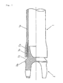
- Figs. 1 and 2 show a propeller shaft having a cylindrical main body 1 formed of FRP, which is obtained by reinforcing a thermosetting resin, such as epoxy resin, unsaturated polyester resin, phenol resin, vinyl ester resin or polyimide resin, or a thermoplastic resin, such as polyamide resin, polycarbonate resin, or polyether imide resin, by means of reinforcing fibers of high strength and high elastic modulus, such as carbon fibers, glass fibers, or polyaramid fibers.
- Metal joints 2 are joined to one and the other end of the main body 1 by press fitting.
- This propeller shaft is symmetrical about the midpoint thereof with respect to the longitudinal direction.
- the main body 1 has a main layer 1a having a uniform inner diameter, extending over the entire length thereof, and including reinforcing fibers helically wound at an angle of ⁇ 5 ⁇ 30° with respect to the axial dimension, and sub-layers (layers in which reinforcing fibers are arranged at an angle of ⁇ 80 ⁇ 90° with respect to the axial dimension) 1b formed at the ends of the main body 1 so as to be integral with and internally of the main layer 1a and including hooped reinforcing fibers.
- the main layer 1a mainly serves to improve the bending elastic modulus in the axial direction of the main body 1 to thereby enhance the flexural resonance frequency, critical revolution, and torsional strength of the propeller shaft.
- the sub-layers 1b mainly serve to impart to the ends of the main body 1, to which the joints are joined by press fitting, a strength large enough to withstand the force applied at the time of press fitting without preventing the progress of rupture as described below, and transmit the torque (torsional torque) from the joints 2 to the main body 1.
- the main body 1 can be formed, for example, by the filament winding method.
- a bundle of reinforcing fibers impregnated with resin is hooped around one end of a mandrel to form a sub-layer to a desired thickness and in a desired length, and then the bundle of reinforcing fibers impregnated with resin is passed as it is to the other end of the mandrel to form a sub-layer at the other end in a similar manner. Subsequently, a bundle of fibers impregnated with resin is helically wound while reciprocating the bundle of layers impregnated with resin between one and the other end to thereby form a main layer having a desired thickness.
- the resin is cured or solidified, preferably rotating them the while. Then, the mandrel is drawn out to thereby obtain the main body.
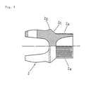
- Each joint 2 is in contact with the inner side of the sub-layer 1b, and has a joint surface 2a that is somewhat shorter than the associated sub-layer 1b.
- the outer diameter of that section of the joint where the joint surface 2a is formed is slightly larger than the inner diameter of the main body 1 before press fitting.
- the sub-layer 1b exists internally, and the main layer 1a on the outer side, so that the circumferential tensile strength generated in the main body 1 as a result of the press fitting is mainly borne by the sub-layer 1b.
- the distortion of the main body 1 is largest on the inner periphery and diminishes toward the outer periphery.
- the sub-layer which is situated internally of the main layer 1a has a relatively large tensile rupture ductility, while the main layer 1a has a relatively small rupture ductility, with the result that an effective joint condition is realized.
- the joining force also varies with the area, surface condition, etc. of the joint surface 2a.
- the ratio of the press fitting margin to the inner diameter of the main body 1 is determined within the range of 0.001 ⁇ 0.02, and the length of the joint surface 2a as measured along the axial direction of the main body 1 is set to be not smaller than 1/10 of the inner diameter of the main body 1. Further, as shown in Fig.
- the above-mentioned joint 2 includes a ring-like protrusion 2b whose outer diameter is somewhat larger than the inner diameter of the main body 1, and a slope 2c descending from this protrusion 2b toward the joint surface 2a.
- the protrusion 2b and the slope 2c constitute a compressive load transmitting section which concentrates a compressive load acting in the axial direction of the joint 2 on the interface between the main layer 1a and the sub-layer 1b to thereby separate the main layer 1a and the sub-layer 1b from each other. It is desirable for the angle which the slope 2c makes with the main body 1 to be in the range of 15 ⁇ 45°.
- the joint 2 When an axial compressive load is applied to the propeller shaft described above, the joint 2 is pressed against the main body 1 to thereby forcibly enlarge the main body 1 under the action of the slope 2c of the protrusion 2b, thereby generating a circumferential tensile strain. Then, while the sub-layer 1b, which is situated internally, remains unbroken due to its high tensile rupture ductility, the main layer 1a, which is situated externally, suffers rupture due to its relatively low tensile rupture ductility. This rupture causes inter-layer exfoliation between the main layer 1a and the sub-layer 1b. That is, the main layer 1a and the sub-layer 1b are separated from each other. From this stage onward, the rupture proceeds rapidly. However, the sub-layer 1b, which is joined to the joint 2, does not suffer rupture but moves axially through the main body 1 while destroying the main layer 1a with the joint 2 as it moves along.
- the axial energy is absorbed through the rupture of the main layer 1a.
- the initial rupture of the main body 1 is induced by the slope 2c of the joint 2, and the protrusion 2b forcibly enlarges the main layer 1a.
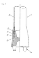
- Fig. 4 shows a propeller shaft according to another embodiment of this invention.
- what corresponds to the slope 2c of the ring-like protrusion 2b, shown in Fig. 1 provides an erect surface 2d that is opposed to the outer axial end surface of the sub-layer 1b.
- the outer diameter of the protrusion 2b is equal to that of the sub-layer 1b.
- a compressive load acting in the axial direction is transmitted to the sub-layer 1b from the erect surface 2d, which is opposed thereto, and further transmitted to the main layer 1a.
- this embodiment differs from the above-described one in that it is the sub-layer 1b that moves while forcibly enlarging the main layer 1a, and the protrusion 2b does not contribute to this forcible enlargement.
- the same effect is to be achieved by making the outer diameter of the protrusion 2b smaller than that of the sub-layer 1b.
- the erect surface 2d may or may not abut the outer axial end surface of the sub-layer 1b.
- the protrusion 2b in the embodiment shown in Figs. 4 and 5, it is also possible, as shown in Fig. 6, for the protrusion 2b to consist of a plurality of protrusions arranged circumferentially on the joint 2 to form a ring-like configuration as a whole. Furthermore, as shown in Fig. 7, it is also possible to partially bevel the outer end surface of the main body, opposed to the protrusion 2b. This localizes the stress that is applied to the sub-layer 1b when the axial compressive load is applied to the joint 2 in the axial direction thereof. Furthermore, the shearing stress acting on the interface between the main layer 1a and the sub-layer 1b is also localized, with the result that the inter-layer exfoliation or rupture is brought about and caused to proceed more reliably. Further, this leads to an increase in the degree of freedom with respect to the starting load for causing the exfoliation or rupture.
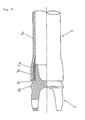
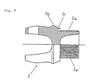
- Figs. 8 and 9 show a propeller shaft according to still another embodiment of this invention.
- the main body 1 is formed as a component that is perfectly identical with that of the above-described embodiments, whereas the construction of the compressive load transmitting section of the joint 2 differs from those in the above embodiments.
- the joint 2 has a ring-like protrusion 2b situated adjacent to the joint surface 2a and having an outer diameter that is somewhat larger than the inner diameter of the main body 1.
- a ring-like protrusion 2b Formed on this ring-like protrusion 2b is a likewise ring-shaped wedge 2f, the tip of which is opposed to the interface between the main layer 1a and the sub-layer 1b.
- the protrusion 2b and the wedge 2f constitute a wedge means, which causes a compressive load acting in the axial direction of the joint 2 to be applied to the interface between the main layer 1a and the sub-layer 1b, thereby separating the main layer 1a and the sub-layer 1b from each other at this interface.
- the wedge may be a single or double-faced one.
- the single-faced structure, in which the face provides an external periphery is the more preferable.
- the rupture of the main layer 1a proceeds rapidly.
- the sub-layer 1b which is joined to the joint 2 does not rupture but moves axially through the main body 1 while destroying the main layer 1a with the joint 2 as it moves along.
- the axial energy is absorbed through rupture of the main layer 1a.
- the initial rupture of the main body 1 is induced by the wedge 2f of the joint 2, and the protrusion 2b enlarges the main layer 1a.
- the main body is symmetrical about the midpoint with respect to the length dimension thereof.
- joints described above have a serration in the joint section.
- Such a joint can be joined to the main body more firmly, which is advantageous from the viewpoint of the transmission of torsional torque.
- joint is joined by press fitting
- press fitting is combined with an adhesive
- the joint that is joined to one end of the main body is the same as that joined to the other end thereof. That is, these propeller shafts are symmetrical about the midpoint with respect to the length dimension.
- this is advantageous in that the number of kinds of parts is relatively small, it is also possible to provide a joint having no compressive load transmitting section at the other end of the main body since it is not absolutely necessary for the rupture of the main body to proceed simultaneously from both ends thereof.
- the joint at the other end of the main body may be formed such that, though of a configuration similar to that shown in Fig.
- the erect surface 2d functions as a stopper at the time of press fitting, and, further, as a seating for receiving a compressive load applied to the main body.
- no joint may be joined to the other end of the main body, with a flange or the like for mounting a joint being joined thereto instead.
- the sub-layer 1b When considered from the viewpoint of the progress of rupture in the main body described above, it is desirable for the sub-layer 1b to be formed such that its inner end portion, which is opposite to the outer end portion, has a wedge-shaped longitudinal-sectional configuration as shown in Fig. 1, etc. Furthermore, as shown in Fig. 12, it is also desirable for the thickness of the sub-layer to be gradually diminished from the axially outer end surface toward the axially inner end surface thereof.
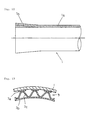
- Fig. 13 shows an example of such a damper.
- the damper 3 which is formed of thick paper, plastic film, non woven fabric of synthetic fiber or the like, comprises a plurality of frictional engagement sections 3a arranged along the inner peripheral surface of the main body 1, a cylindrical holding section 3b spaced apart from the inner peripheral surface of the main body 1, and an elastic support section 3c of a corrugated type which resiliently supports the frictional engagement sections 3a by pressing them against the inner peripheral surface of the main body 1.
- the damper 3 which is formed of thick paper, plastic film, non woven fabric of synthetic fiber or the like, comprises a plurality of frictional engagement sections 3a arranged along the inner peripheral surface of the main body 1, a cylindrical holding section 3b spaced apart from the inner peripheral surface of the main body 1, and an elastic support section 3c of a corrugated type which resiliently supports the frictional engagement sections 3a by pressing them against the inner peripheral surface of the main body 1.
- the damper when seen as a whole, the damper is formed as a cylindrical body having a tendency to expand in the directions indicated by the arrows.
- the damper is incorporated into the main body such that the frictional engagement sections 3a are held slidable on and pressed against the inner peripheral surface of the main body 1 by the elastic support section 3c.
- Fig. 15 shows another example of the damper.
- the apex sections of the corrugated-type elastic support section 3c also function as the frictional engagement sections 3a in the damper shown in Figs. 13 and 14.
- a main body 1 as shown in Fig. 1 was obtained, which had an end-portion outer diameter of 80 mm, a sub-layer outer diameter of 75 mm, an inner diameter of 70 mm, and a length of 1,200 mm.
- a metal joint 2 as shown in Fig. 2 whose joint surface 2a had a serration, an outer diameter of 70.5 mm, and a length of 40 mm, whose protrusion 2b had an outer diameter of 80 mm, and whose slope 2c made an angle of 30° with respect to the axial dimension of the main body 1, was joined to each end of the above main body 1 by press fitting to thereby obtain a propeller shaft according to this invention'as shown in Fig. 1.
- the requisite force for the press fitting was 7,000 kgf.
- the propeller shaft was subjected to a torsion test.
- the torsional strength of the propeller shaft was found to be 350 kgf.m, and the critical revolution 8,000 rpm, both of which proved sufficient as a propeller shaft for automobiles.
- a propeller shaft as shown in Fig. 4 was obtained in the same manner as in Example 1 except that a joint was used the protrusion 2b of which had an outer diameter of 75 mm, which was the same as that of the sub-layer 1b.
- the propeller shaft was found to have a torsional strength of 350 kgf.m and a critical revolution of 8,000 rpm, both of which proved satisfactory for a propeller shaft for automobiles.
- the requisite force for the press fitting was 7,000 kgf.
- the propeller shaft of this invention is equipped with a compressive load transmitting section which concentrates a compressive load acting in the axial direction of the joint on the interface between the main layer and the sub-layer to thereby separate the main layer and the sub-layer from each other.
Landscapes
- Engineering & Computer Science (AREA)
- General Engineering & Computer Science (AREA)
- Mechanical Engineering (AREA)
- Ocean & Marine Engineering (AREA)
- Shafts, Cranks, Connecting Bars, And Related Bearings (AREA)
- Excavating Of Shafts Or Tunnels (AREA)
Claims (14)
- Arbre de transmission comprenant un corps principal cylindrique (1) réalisé en plastique renforcé par des fibres (FRP) et un premier joint (2) qui est relié à une extrémité du corps principal (1), ledit corps principal (1) incluant une couche principale (1a) s'étendant sur toute sa longueur, et une sous-couche (1b) formée à ladite extrémité dudit corps principal (1) de façon à être intégrale avec et à l'intérieur de ladite couche principale (1a), où ledit premier joint (2) présente une section de transmission de charge de compression (2c, 2d, 2f) conçue pour diriger sur l'arbre une charge de compression agissant axialement dans la direction axiale dudit joint (2), où le premier joint comprend une denture (2c) sur une surface de joint (2a) entre ledit premier joint et ledit corps principal s'étendant dans une direction axiale de celui-ci, caractérisé en ce que la jonction entre ledit premier joint réalisé en métal et ladite sous-couche est effectuée par ajustage serré, et en ce que ladite section de transmission de charge de compression dirige ladite charge de compression pour la concentrer sur l'interface entre ladite couche principale (1a) et ladite sous-couche (1b) pour séparer ainsi ladite couche principale (1a) et ladite sous-couche (1b) l'une de l'autre à ladite interface.
- Arbre de transmission selon la revendication 1, où l'arbre de transmission comprend en outre un second joint (2) réalisé en métal qui est relié à l'autre extrémité dudit corps principal (1), ledit corps principal (1) incluant une seconde sous-couche (1b) formée à ladite autre extrémité dudit corps principal (1) de façon à être intégrale avec et à l'intérieur de ladite couche principale (1a), ledit second joint (2) étant équipé d'une section de transmission de charge de compression apte à concentrer une charge de compression agissant axialement dans la direction axiale dudit second joint (2) sur une interface entre ladite couche principale (1a) et ladite seconde sous-couche (1b) pour séparer ainsi ladite couche principale (1a) et ladite seconde sous-couche (1b) l'une de l'autre à ladite interface entre celles-ci, où le second joint présente une denture sur une surface dudit second joint s'étendant dans une direction axiale de celui-ci, et où la jonction entre ledit second joint et ladite sous-couche est effectuée par ajustage serré.
- Arbre de transmission selon la revendication 1 ou la revendication 2, où ladite couche principale (1a) s'étendant sur toute la longueur dudit corps principal (1) comprend des fibres de renforcement enroulées hélicoïdalement, et la ou chaque sous-couche respective (1b) formée à la ou chaque extrémité respective dudit corps principal (1) de façon à être intégrale avec et à l'intérieur de ladite couche principale (1a) comprend des fibres de renforcement bouclées.
- Arbre de transmission selon la revendication 3, où lesdites fibres de renforcement sont enroulées hélicoïdalement selon un angle de ±5 ~ 30° relativement à la direction axiale dudit corps principal (1).
- Arbre de transmission selon l'une des revendications 1 à 4, où le ou chaque joint comprend une ou une surface de joint respective (2a) en contact avec la périphérie interne de la ou de la sous-couche respective (1b).
- Arbre de transmission selon l'une des revendications 1 à 5, où la ou chaque section de transmission de charge de compression présente une ou une portion inclinée respective (2c) descendant vers une ou une surface de joint respective entre le ou chaque joint respectif (2) et la ou chaque sous-couche respective (1b).
- Arbre de transmission selon l'une des revendications 1 à 5, où la ou chaque section de transmission de charge de compression présente une ou une surface d'érection respective (2d) d'un diamètre extérieur qui n'est pas plus grand que le diamètre extérieur de la ou chaque sous-couche respective et opposée à une surface d'extrémité extérieure de la ou de chaque sous-couche respective (1b).
- Arbre de transmission selon la revendication 7, où la ou chaque surface d'érection respective (2d) s'étend d'une manière annulaire autour de la circonférence du ou de chaque joint respectif (2).
- Arbre de transmission selon la revendication 8, dans lequel la surface de la ou de chaque extrémité dudit corps principal (1) est partiellement biseautée.
- Arbre de transmission selon la revendication 7, où une pluralité des surfaces d'érection (2d) est agencée autour de la circonférence de la ou de chaque joint (2).
- Arbre de transmission selon l'une des revendications 1 à 5, où la ou chaque section de transmission de charge de compression est équipée d'un moyen de coin (2f).
- Arbre de transmission selon la revendication 11, où le ou chaque moyen de coin présente un coin annulaire (2f) s'étendant le long d'une ligne circulaire qui est définie par la ou chaque interface respective entre ladite couche principale (1a) et la ou chaque sous-couche respective (1b) à la ou chaque extrémité dudit corps principal (1).
- Arbre de transmission selon la revendication 11, où ledit moyen de coin présente une pluralité de coins (2f) agencés le long d'une ligne circulaire qui est définie par la ou chaque interface respective entre ladite couche principale (1a) et la ou chaque sous-couche respective (1b) à la ou chaque extrémité dudit corps principal (1).
- Arbre de transmission selon l'une des revendications 1 à 13, où ledit corps principal (1) contient un amortisseur (3).
Applications Claiming Priority (7)
| Application Number | Priority Date | Filing Date | Title |
|---|---|---|---|
| JP30031293 | 1993-11-30 | ||
| JP300312/93 | 1993-11-30 | ||
| JP30031393 | 1993-11-30 | ||
| JP30031393 | 1993-11-30 | ||
| JP300313/93 | 1993-11-30 | ||
| JP30031293 | 1993-11-30 | ||
| PCT/JP1994/001996 WO1995015444A1 (fr) | 1993-11-30 | 1994-11-29 | Arbre de transmission |
Publications (3)
| Publication Number | Publication Date |
|---|---|
| EP0683328A1 EP0683328A1 (fr) | 1995-11-22 |
| EP0683328A4 EP0683328A4 (fr) | 1997-08-20 |
| EP0683328B1 true EP0683328B1 (fr) | 2002-02-20 |
Family
ID=26562292
Family Applications (1)
| Application Number | Title | Priority Date | Filing Date |
|---|---|---|---|
| EP95901602A Expired - Lifetime EP0683328B1 (fr) | 1993-11-30 | 1994-11-29 | Arbre de transmission |
Country Status (8)
| Country | Link |
|---|---|
| US (1) | US20010001769A1 (fr) |
| EP (1) | EP0683328B1 (fr) |
| KR (1) | KR100317474B1 (fr) |
| AU (1) | AU1077195A (fr) |
| CA (1) | CA2155099A1 (fr) |
| DE (1) | DE69429911T2 (fr) |
| ES (1) | ES2173164T3 (fr) |
| WO (1) | WO1995015444A1 (fr) |
Cited By (1)
| Publication number | Priority date | Publication date | Assignee | Title |
|---|---|---|---|---|
| DE112007001768B4 (de) * | 2006-08-28 | 2018-05-30 | Xperion Gmbh | Antriebswelle |
Families Citing this family (13)
| Publication number | Priority date | Publication date | Assignee | Title |
|---|---|---|---|---|
| ES2129322B1 (es) * | 1996-04-18 | 2000-02-01 | Castellon Melchor Daumal | Perfeccionamientos en los arboles telescopicos. |
| KR100515800B1 (ko) * | 2002-10-23 | 2005-09-21 | 한국과학기술원 | 복합재료가 내면에 적층된 동력전달축 및 그 제조방법 |
| FR2846942A1 (fr) * | 2002-11-13 | 2004-05-14 | Soc D Const Aeronautique Auver | Arbre et procede de transmission pour helice d'avion deportee |
| DE102008025238A1 (de) * | 2007-06-21 | 2008-12-24 | Ifa-Technologies Gmbh | Längswelle |
| GB0722933D0 (en) | 2007-11-23 | 2008-01-02 | Dewhurst Mike | Mechanical connection between composite tubular structure and an end fitting of any engineering material |
| DE102009012479B4 (de) * | 2009-03-12 | 2012-05-03 | Sew-Eurodrive Gmbh & Co. Kg | Verbindung einer Welle mit einem Aufnahmeteil |
| DE102013103769B3 (de) * | 2013-04-15 | 2014-10-16 | Inometa Gmbh & Co. Kg | Vorrichtung für eine Antriebswelle eines Kraftfahrzeuges und Verfahren zum Herstellen |
| US9441374B2 (en) | 2014-04-08 | 2016-09-13 | Goodrich Corporation | Struts and methods utilizing a compression collar |
| EP3025846B1 (fr) * | 2014-11-28 | 2019-11-13 | Crompton Technology Group Limited | Entretoise de tension/compression composite |
| GB2538511B (en) * | 2015-05-18 | 2020-12-16 | Lentus Composites Ltd | Shaft arrangement |
| DE102016121660A1 (de) * | 2016-11-11 | 2018-05-17 | xperion components GmbH & Co. KG | Aufprallenergie absorbierende antriebswelle für ein motorfahrzeug |
| KR20180076574A (ko) * | 2016-12-28 | 2018-07-06 | 주식회사 신금하 | 프로펠러 필라멘트 와인딩 샤프트와 금속 플랜지 사이 연결 부위의 직물형 카본/에폭시 프리프레그 보강 적층 구조 및 방법 |
| US11649849B2 (en) | 2021-01-22 | 2023-05-16 | Hamilton Sundstrand Corporation | Buckling-resistant thin-wall drive shafts |
Family Cites Families (3)
| Publication number | Priority date | Publication date | Assignee | Title |
|---|---|---|---|---|
| JPS6041246B2 (ja) * | 1980-02-20 | 1985-09-14 | 東レ株式会社 | 繊維強化プラスチツク製プロペラシヤフト |
| JPH0191118U (fr) * | 1987-12-08 | 1989-06-15 | ||
| JPH0747973B2 (ja) * | 1989-06-24 | 1995-05-24 | ジー・ケー・エヌ・オートモーティヴ・アクチエンゲゼルシャフト | 接続機構 |
-
1994
- 1994-11-29 CA CA002155099A patent/CA2155099A1/fr not_active Abandoned
- 1994-11-29 EP EP95901602A patent/EP0683328B1/fr not_active Expired - Lifetime
- 1994-11-29 WO PCT/JP1994/001996 patent/WO1995015444A1/fr not_active Ceased
- 1994-11-29 KR KR1019950703142A patent/KR100317474B1/ko not_active Expired - Fee Related
- 1994-11-29 ES ES95901602T patent/ES2173164T3/es not_active Expired - Lifetime
- 1994-11-29 DE DE69429911T patent/DE69429911T2/de not_active Expired - Lifetime
- 1994-11-29 AU AU10771/95A patent/AU1077195A/en not_active Abandoned
-
2001
- 2001-01-19 US US09/764,319 patent/US20010001769A1/en not_active Abandoned
Cited By (1)
| Publication number | Priority date | Publication date | Assignee | Title |
|---|---|---|---|---|
| DE112007001768B4 (de) * | 2006-08-28 | 2018-05-30 | Xperion Gmbh | Antriebswelle |
Also Published As
| Publication number | Publication date |
|---|---|
| ES2173164T3 (es) | 2002-10-16 |
| CA2155099A1 (fr) | 1995-06-08 |
| EP0683328A1 (fr) | 1995-11-22 |
| US20010001769A1 (en) | 2001-05-24 |
| WO1995015444A1 (fr) | 1995-06-08 |
| DE69429911T2 (de) | 2002-09-05 |
| KR100317474B1 (ko) | 2002-07-02 |
| DE69429911D1 (de) | 2002-03-28 |
| AU1077195A (en) | 1995-06-19 |
| EP0683328A4 (fr) | 1997-08-20 |
| KR960700417A (ko) | 1996-01-20 |
Similar Documents
| Publication | Publication Date | Title |
|---|---|---|
| US6190263B1 (en) | Propeller shaft including compressive load transmitting section | |
| EP0683328B1 (fr) | Arbre de transmission | |
| US7874925B2 (en) | Transmission shaft joint design | |
| US8118064B2 (en) | Fiber reinforced plastic pipe and power transmission shaft employing the same | |
| US6682436B2 (en) | Shock absorbing tube | |
| JPH09175202A (ja) | 車両用プロペラシャフト | |
| JP2002039153A (ja) | プロペラシャフトおよびその製造方法 | |
| JP3063583B2 (ja) | プロペラシャフト | |
| JP3218892B2 (ja) | プロペラシャフト | |
| JP3269287B2 (ja) | Frp筒体およびその製造方法 | |
| JP3456596B2 (ja) | エネルギー吸収部材 | |
| US20030157988A1 (en) | Fiber reinforced plastic propeller shaft | |
| JP3578284B2 (ja) | プロペラシャフト | |
| JP3218891B2 (ja) | プロペラシャフト | |
| JP2010083253A (ja) | プロペラシャフト | |
| JP3582322B2 (ja) | プロペラシャフト | |
| JP2001355626A (ja) | 複合材製駆動軸 | |
| JP2000329130A (ja) | プロペラシャフト | |
| JPH0791433A (ja) | プロペラシャフトおよびその製造方法 | |
| JP3433850B2 (ja) | Frp筒体およびその製造方法 | |
| JP3292351B2 (ja) | Frp筒体 | |
| JPH0791431A (ja) | プロペラシャフト | |
| JP3391298B2 (ja) | プロペラシャフト | |
| JP2006183728A (ja) | プロペラシャフト | |
| JPH0742974B2 (ja) | 繊維強化プラスチック製伝動軸の製造方法 |
Legal Events
| Date | Code | Title | Description |
|---|---|---|---|
| PUAI | Public reference made under article 153(3) epc to a published international application that has entered the european phase |
Free format text: ORIGINAL CODE: 0009012 |
|
| 17P | Request for examination filed |
Effective date: 19950821 |
|
| AK | Designated contracting states |
Kind code of ref document: A1 Designated state(s): DE ES FR GB IT SE |
|
| A4 | Supplementary search report drawn up and despatched |
Effective date: 19970704 |
|
| AK | Designated contracting states |
Kind code of ref document: A4 Designated state(s): AT BE CH DE DK ES FR GB GR IE IT LI NL PT SE |
|
| 17Q | First examination report despatched |
Effective date: 19981120 |
|
| GRAG | Despatch of communication of intention to grant |
Free format text: ORIGINAL CODE: EPIDOS AGRA |
|
| GRAG | Despatch of communication of intention to grant |
Free format text: ORIGINAL CODE: EPIDOS AGRA |
|
| GRAH | Despatch of communication of intention to grant a patent |
Free format text: ORIGINAL CODE: EPIDOS IGRA |
|
| GRAG | Despatch of communication of intention to grant |
Free format text: ORIGINAL CODE: EPIDOS AGRA |
|
| GRAG | Despatch of communication of intention to grant |
Free format text: ORIGINAL CODE: EPIDOS AGRA |
|
| GRAH | Despatch of communication of intention to grant a patent |
Free format text: ORIGINAL CODE: EPIDOS IGRA |
|
| GRAH | Despatch of communication of intention to grant a patent |
Free format text: ORIGINAL CODE: EPIDOS IGRA |
|
| RBV | Designated contracting states (corrected) |
Designated state(s): DE ES FR GB IT SE |
|
| REG | Reference to a national code |
Ref country code: GB Ref legal event code: IF02 |
|
| GRAA | (expected) grant |
Free format text: ORIGINAL CODE: 0009210 |
|
| AK | Designated contracting states |
Kind code of ref document: B1 Designated state(s): DE ES FR GB IT SE |
|
| REF | Corresponds to: |
Ref document number: 69429911 Country of ref document: DE Date of ref document: 20020328 |
|
| ET | Fr: translation filed | ||
| REG | Reference to a national code |
Ref country code: ES Ref legal event code: FG2A Ref document number: 2173164 Country of ref document: ES Kind code of ref document: T3 |
|
| PLBE | No opposition filed within time limit |
Free format text: ORIGINAL CODE: 0009261 |
|
| STAA | Information on the status of an ep patent application or granted ep patent |
Free format text: STATUS: NO OPPOSITION FILED WITHIN TIME LIMIT |
|
| 26N | No opposition filed |
Effective date: 20021121 |
|
| PGFP | Annual fee paid to national office [announced via postgrant information from national office to epo] |
Ref country code: SE Payment date: 20061106 Year of fee payment: 13 |
|
| PGFP | Annual fee paid to national office [announced via postgrant information from national office to epo] |
Ref country code: ES Payment date: 20061128 Year of fee payment: 13 |
|
| EUG | Se: european patent has lapsed | ||
| PG25 | Lapsed in a contracting state [announced via postgrant information from national office to epo] |
Ref country code: SE Free format text: LAPSE BECAUSE OF NON-PAYMENT OF DUE FEES Effective date: 20071130 |
|
| REG | Reference to a national code |
Ref country code: ES Ref legal event code: FD2A Effective date: 20071130 |
|
| PG25 | Lapsed in a contracting state [announced via postgrant information from national office to epo] |
Ref country code: ES Free format text: LAPSE BECAUSE OF NON-PAYMENT OF DUE FEES Effective date: 20071130 |
|
| PGFP | Annual fee paid to national office [announced via postgrant information from national office to epo] |
Ref country code: FR Payment date: 20131108 Year of fee payment: 20 Ref country code: GB Payment date: 20131127 Year of fee payment: 20 Ref country code: DE Payment date: 20131127 Year of fee payment: 20 |
|
| PGFP | Annual fee paid to national office [announced via postgrant information from national office to epo] |
Ref country code: IT Payment date: 20131115 Year of fee payment: 20 |
|
| REG | Reference to a national code |
Ref country code: DE Ref legal event code: R071 Ref document number: 69429911 Country of ref document: DE |
|
| REG | Reference to a national code |
Ref country code: GB Ref legal event code: PE20 Expiry date: 20141128 |
|
| PG25 | Lapsed in a contracting state [announced via postgrant information from national office to epo] |
Ref country code: GB Free format text: LAPSE BECAUSE OF EXPIRATION OF PROTECTION Effective date: 20141128 |