EP0683348A2 - Dispositif pour l'étanchement la paroi d'une canalisation au niveau des jonctions entre canalisations principales et branchements latéraux - Google Patents
Dispositif pour l'étanchement la paroi d'une canalisation au niveau des jonctions entre canalisations principales et branchements latéraux Download PDFInfo
- Publication number
- EP0683348A2 EP0683348A2 EP95107387A EP95107387A EP0683348A2 EP 0683348 A2 EP0683348 A2 EP 0683348A2 EP 95107387 A EP95107387 A EP 95107387A EP 95107387 A EP95107387 A EP 95107387A EP 0683348 A2 EP0683348 A2 EP 0683348A2
- Authority
- EP
- European Patent Office
- Prior art keywords
- expansion body
- shield
- channel
- wall
- duct
- Prior art date
- Legal status (The legal status is an assumption and is not a legal conclusion. Google has not performed a legal analysis and makes no representation as to the accuracy of the status listed.)
- Withdrawn
Links
- 238000007789 sealing Methods 0.000 title claims abstract description 24
- 239000013013 elastic material Substances 0.000 claims abstract description 5
- 150000001875 compounds Chemical class 0.000 claims description 14
- 238000009415 formwork Methods 0.000 claims description 13
- 239000000463 material Substances 0.000 claims description 3
- 230000006835 compression Effects 0.000 claims description 2
- 238000007906 compression Methods 0.000 claims description 2
- 239000011248 coating agent Substances 0.000 claims 1
- 238000000576 coating method Methods 0.000 claims 1
- NMFHJNAPXOMSRX-PUPDPRJKSA-N [(1r)-3-(3,4-dimethoxyphenyl)-1-[3-(2-morpholin-4-ylethoxy)phenyl]propyl] (2s)-1-[(2s)-2-(3,4,5-trimethoxyphenyl)butanoyl]piperidine-2-carboxylate Chemical compound C([C@@H](OC(=O)[C@@H]1CCCCN1C(=O)[C@@H](CC)C=1C=C(OC)C(OC)=C(OC)C=1)C=1C=C(OCCN2CCOCC2)C=CC=1)CC1=CC=C(OC)C(OC)=C1 NMFHJNAPXOMSRX-PUPDPRJKSA-N 0.000 description 4
- 238000009418 renovation Methods 0.000 description 4
- 238000009420 retrofitting Methods 0.000 description 3
- 230000001154 acute effect Effects 0.000 description 2
- 230000002950 deficient Effects 0.000 description 2
- 238000000034 method Methods 0.000 description 2
- 230000000717 retained effect Effects 0.000 description 2
- 230000006978 adaptation Effects 0.000 description 1
- 230000015572 biosynthetic process Effects 0.000 description 1
- 238000006243 chemical reaction Methods 0.000 description 1
- 238000002347 injection Methods 0.000 description 1
- 239000007924 injection Substances 0.000 description 1
- 239000007788 liquid Substances 0.000 description 1
- 238000003754 machining Methods 0.000 description 1
- 230000035515 penetration Effects 0.000 description 1
- 239000002985 plastic film Substances 0.000 description 1
- 229920006255 plastic film Polymers 0.000 description 1
- 238000005086 pumping Methods 0.000 description 1
- 239000000565 sealant Substances 0.000 description 1
- 239000003566 sealing material Substances 0.000 description 1
- 238000004804 winding Methods 0.000 description 1
Images

Classifications
-
- F—MECHANICAL ENGINEERING; LIGHTING; HEATING; WEAPONS; BLASTING
- F16—ENGINEERING ELEMENTS AND UNITS; GENERAL MEASURES FOR PRODUCING AND MAINTAINING EFFECTIVE FUNCTIONING OF MACHINES OR INSTALLATIONS; THERMAL INSULATION IN GENERAL
- F16L—PIPES; JOINTS OR FITTINGS FOR PIPES; SUPPORTS FOR PIPES, CABLES OR PROTECTIVE TUBING; MEANS FOR THERMAL INSULATION IN GENERAL
- F16L55/00—Devices or appurtenances for use in, or in connection with, pipes or pipe systems
- F16L55/26—Pigs or moles, i.e. devices movable in a pipe or conduit with or without self-contained propulsion means
- F16L55/265—Pigs or moles, i.e. devices movable in a pipe or conduit with or without self-contained propulsion means specially adapted for work at or near a junction between a main and a lateral pipe
-
- F—MECHANICAL ENGINEERING; LIGHTING; HEATING; WEAPONS; BLASTING
- F16—ENGINEERING ELEMENTS AND UNITS; GENERAL MEASURES FOR PRODUCING AND MAINTAINING EFFECTIVE FUNCTIONING OF MACHINES OR INSTALLATIONS; THERMAL INSULATION IN GENERAL
- F16L—PIPES; JOINTS OR FITTINGS FOR PIPES; SUPPORTS FOR PIPES, CABLES OR PROTECTIVE TUBING; MEANS FOR THERMAL INSULATION IN GENERAL
- F16L55/00—Devices or appurtenances for use in, or in connection with, pipes or pipe systems
- F16L55/16—Devices for covering leaks in pipes or hoses, e.g. hose-menders
- F16L55/179—Devices for covering leaks in pipes or hoses, e.g. hose-menders specially adapted for bends, branch units, branching pipes or the like
Definitions
- the invention relates to a device for sealing duct walls in the region of the connection of a secondary duct to a main duct, with a carrying and positioning device which can be moved and fixed in the main duct for a shield which can be applied to the wall of the main duct in the region of the secondary duct connection and which can be adapted to the wall curvature an inflatable expandable body which can be introduced into the secondary duct, which in the inflated state rests against the wall of the secondary duct and then forms a formwork together with the shield, such that in the space between this formwork and the adjacent walls of the main and secondary duct a sealing compound can be pressed in, which forms duct wall regions which are sealed after the expansion body has been removed from the secondary duct and the shield has been removed from the duct connection region.
- the expansion body is a tubular balloon in the uninflated state, which protrudes from the shield in the direction of the inner wall of the main line.
- a formwork is pushed over this stretchable cylinder body, the cylinder body together with the pushed-on formwork is introduced into the secondary duct by moving the shield in a radial direction to the main duct and then the balloon is pressurized.
- the formwork is expanded and pressed against the inner wall of the secondary line.
- the space between the formwork, the shield and the damaged pipe walls is then filled with a sealing compound.
- this device makes it possible to remotely seal sewer connection areas without the secondary duct, as in other renovation methods, having to be drilled out or milled out after the sealing compound has been introduced.
- the expansion body in the non-inflated state protrudes radially from the shield even in its full length, which is essentially maintained even after it has been introduced into the secondary channel. This can lead to problems when moving the shield along the main line and when positioning it in relation to the junction of the secondary channel in the main channel.
- the maximum length of the tubular balloon is limited by the diameter of the main channel, so that the maximum depth of penetration into the secondary channel and thus the maximum possible machining depth in the secondary channel is limited, starting from the junction.
- the known device presupposes secondary channels branching perpendicularly and axially to the main channel. It is hardly suitable for secondary channels branching off at a noticeably different angle from 90 degrees, since the cylinder body with the formwork pushed on would then no longer be able to be moved into the secondary channel, at least not in such a way that the formwork was flush with the entire circumference of the main channel directly adjacent wall area of the secondary duct covers. Furthermore, the known device requires the use of an additional formwork component pushed onto the cylinder body. Use without formwork components is not intended. Problems with pulling out the cylinder body from the secondary duct would then also have to be expected. The adaptation of the device to different nominal duct sizes is possible at best by complex retrofitting of components.
- a remotely controllable device for repairing channel outlets is also shown in German Offenlegungsschrift DE 42 13 898.
- This device is also equipped with an expansion body which, with its entire length, which is essentially retained even after inflation, is moved radially to the main channel, because the inflatable jacket of the Expansion body surrounds a rigid cylindrical support body.
- This device therefore also has the disadvantages mentioned above.
- European published patent application EP 114 727 A1 discloses a sewer rehabilitation method developed in the USA and known as the LSS system (Lateral Sealing System), in which a packer with two inflatable packer sleeves, which are connected to one another by an intermediate piece, enters the main duct is introduced. From the intermediate part, a hose with compressed air can be inserted into the connecting channels. Injection medium pressed in between the pipe wall and hose seals the channel. Sealing compound also gets into the annular space between the intermediate part and the wall of the main channel. In practical use, it has been found that the packer can only be removed with great difficulty in the case of large quantities of sealing material to be pressed, in particular strongly hardening material.
- LSS system Lateral Sealing System
- the intermediate part for the angular positioning of the hose relative to the junction of the secondary channel is rotatably driven between the end sleeves, and a device for unwinding or winding up the hose is also accommodated in the intermediate part, the entire device is extremely expensive to construct. Like the devices previously recognized in the prior art, it is tied to nominal nominal channel widths of relatively narrow diameter ranges and can therefore only be used with little flexibility without expensive retrofitting.
- the invention has for its object to avoid the disadvantages mentioned above in the prior art, ie to provide a device for sealing channel walls in the area of the connection of a secondary channel to a main channel, which with little design effort in one Large duct nominal diameter range can be used without retrofitting, is easy to position and can be easily removed from the connection area after sealing.
- the device should also be equally suitable for secondary duct connections which run at an acute angle and / or with a curved pipe axis and / or which are not centered on the main duct.
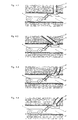
- a device having the features of patent claim 1 that is to say in that, in a device of the generic type, the expansion body is formed exclusively from a layer of elastic material, that the expansion body in the weakly inflated state initially has the shape of a starting from the shield, at the tip is rounded hollow cone, which with increasing inflation changes into a cylindrical shape corresponding to the diameter of the secondary channel and its angle to the main channel, the expansion body increasingly growing into the secondary channel, and that the expansion body can be removed from the secondary channel by reducing the pressure acting on it .
- the subclaims relate to advantageous refinements of the device according to the invention.
- the device corresponding to the invention thus uses an expansion body that has no support body and solely because of its elasticity and its calculated layer thicknesses after the positioning of the shield on the wall of the main channel during inflation automatically and absolutely reliably both in the radial and in the axial direction in the secondary channel grows into it and lies closely against the walls of a secondary duct branching off at any angle, even if the secondary duct is not curved or kinked axially to the main duct or directly behind the connection area.
- the mode of operation of the device is unchanged in the case of secondary ducts of different nominal widths over a large nominal diameter range.
- a certain expansion body can be used in a range from nominal width 100 to nominal width 200 of the secondary duct. Nominal diameter changes with a factor of 2 can therefore still be handled with one and the same expansion body. Conversions to adapt to channel diameters that deviate greatly from the normal channel diameter range therefore only have to be carried out in rare cases, but are then possible without any problems, since the expansion body, which is formed simply from an elastic material layer, can be replaced - and possibly to adapt to the diameter of the main channel also of the shield - requires little assembly effort.
- the expansion body can be relieved of pressure after a very short time, in which case it collapses and can be brought out of the secondary duct without impairing the wall which has just been repaired in any way. Detachment of the expansion body surface by pressure reduction is so gently possible that even not yet fully hardened sealing compound remains intact in the freshly repaired duct wall. Formwork removal of the renovated sewer area is therefore possible very early. In addition, it can be done even faster if a thin, lost separating layer, in particular a plastic film, is applied to the area of the shield facing the wall of the main duct, which remains in the refurbished duct.
- the sealing compound can be conveyed under pressure, in particular via pipes or hoses, and is introduced into the compression gap via several mouthpieces at the base of the expansion body, that is to say in the region of its connection to the shield. It is distributed in particular around the base of the expansion body.
- expansion bodies with a particularly large linear expansion capability from the shield can be used, in the surface of which adjoins the foot, one or more outlet openings for the sealing compound are formed. These outlet openings are connected to movable feed lines which, when the expansion body grows into the secondary channel, track the surface of the expansion body and follow the moving outlet opening.
- the sealant can also be applied in sufficient quantity and under sufficient pressure to damaged areas deeper in the secondary duct.
- the initial layer thickness of the elastic material layer of the expansion body is calculated as a function of its surface extension so that when it inflates, the spatial shape of a hollow cone rounded off at the top is obtained, and that as the inflation increases, there is a progression from the base of the cone, i.e. the shield adapted to the secondary channel, following the conical tip of the cylinder trains.
- This makes it possible for the expansion body to grow into the secondary channel to a sufficient depth with minimized friction on the walls of the secondary channel and, with the opposite shape change behavior, to be separated from the repaired wall after the pressure relief and to be removed from the secondary channel.
- the application can be carried out by means of negative pressure, so that the expansion body can be sucked in behind the contact surface of the sign and then in particular can be completely sunk into a flat box on the sign.
- This position can also be the starting position from which the expansion body is introduced into the secondary channel by being inflated, so that the expansion body does not protrude from the shield at all when the carrying and positioning device is moved in the main channel.
- the layer thickness of the expansion body is otherwise optimized so that its cylindrical shape is largely retained when inserted into the secondary channel, even if parts of the secondary channel wall are missing.
- the wall thickness of the expansion body is calculated in such a way that it can maintain its cylindrical shape corresponding to the nominal size of the secondary channel by controlling the internal pressure of the expansion body and the delivery pressure of the sealing compound, in particular also in the area of the defective wall parts.
- the damaged canal wall is therefore restored very precisely, or missing canal walls are newly formed to fit, so that in most cases a subsequent material-removing canal wall treatment is no longer required in the renovation practice.
- the very special advantage of the device according to the invention lies in the fact that, in contrast to the devices acknowledged at the beginning of the prior art, it is suitable for repairing from any angle to the main channel, also outside its center axis or curved secondary channels. Even if the secondary channel forms an acute angle with the main channel, the expansion body easily grows from the shield into the secondary channel due to its great adaptability when inflated. After sealing, it can then also be removed from the secondary duct just as easily by relieving pressure or applying negative pressure.
- the positioning of the shield in the region of the duct connection is also simplified with the device according to the invention, because the expansion body can be inserted into the secondary duct by inflation when its rounded hollow cone tip is located somewhere within the mouth of the secondary duct.
- the high adaptability of the expansion body to the surrounding channel walls compensates for any positioning inaccuracies. The positioning therefore does not require much effort and is quick and easy to carry out.
- the shield of the device can be formed over a large area and be provided with appropriate outlet openings for sealing compound that the star-shaped crack formation in the main channel, which frequently occurs in practice, is sealed in one operation together with the repair of the secondary channel.
- the shield is able to adapt to the wall curvature within a certain nominal diameter range of the main duct, so that at least the diameter variations that occur frequently in practice are covered, which can vary due to the tolerances permitted by DIN, e.g. B. with different materials.
- DIN e.g. B.
- it can have a rubber-like pad.
- it can be designed as a structure with lamellae which run in the longitudinal direction of the main channel and are bendable relative to one another.
- inflation of the expansion body should generally be understood to mean its expansion by applying internal pressure. This can be done using a gas, especially air. However, it is also conceivable to expand the expansion body by pumping in a liquid.
- the carrying and positioning device of the device according to the invention can, as explained below with reference to the drawing, be formed in different ways.
- the carrying and positioning device is a remote-controllable sewer rehabilitation robot.
- the shield 1 On its head, which can be moved in three degrees of freedom, the shield 1 is fastened, which can be positioned by means of the externally controllable head drive together with the expansion body 2 in the connection region of the secondary duct 3 to the main duct 4.
- FIG. 2 shows that the carrying and positioning device can also comprise a tensioning device 6, which is supported against the wall area of the main channel 4 radially opposite the plate 1 and presses the plate 1 in the channel connection area.
- a tensioning device 6 which is supported against the wall area of the main channel 4 radially opposite the plate 1 and presses the plate 1 in the channel connection area.
- Figure 3 shows a schematic representation that the carrying and positioning device can also be a carriage 7, on which the shield 1 with the expansion body 2 is rotatably mounted about an axis of rotation parallel to the axis of the main channel 4.
- the shield 1 can be positioned particularly reliably in the circumferential direction of the main channel 4.
- the carriage 7 has means for pressing the shield 1 against the wall of the main channel 4.
Landscapes
- Engineering & Computer Science (AREA)
- General Engineering & Computer Science (AREA)
- Mechanical Engineering (AREA)
- Chemical & Material Sciences (AREA)
- Combustion & Propulsion (AREA)
- Pipe Accessories (AREA)
Applications Claiming Priority (2)
| Application Number | Priority Date | Filing Date | Title |
|---|---|---|---|
| DE4417076 | 1994-05-17 | ||
| DE19944417076 DE4417076C2 (de) | 1994-05-17 | 1994-05-17 | Vorrichtung zum Abdichten von Kanalwandungen im Bereich des Anschlusses eines Nebenkanals an einen Hauptkanal |
Publications (2)
| Publication Number | Publication Date |
|---|---|
| EP0683348A2 true EP0683348A2 (fr) | 1995-11-22 |
| EP0683348A3 EP0683348A3 (fr) | 1997-09-03 |
Family
ID=6518172
Family Applications (1)
| Application Number | Title | Priority Date | Filing Date |
|---|---|---|---|
| EP95107387A Withdrawn EP0683348A3 (fr) | 1994-05-17 | 1995-05-16 | Dispositif pour l'étanchement la paroi d'une canalisation au niveau des jonctions entre canalisations principales et branchements latéraux. |
Country Status (2)
| Country | Link |
|---|---|
| EP (1) | EP0683348A3 (fr) |
| DE (1) | DE4417076C2 (fr) |
Cited By (4)
| Publication number | Priority date | Publication date | Assignee | Title |
|---|---|---|---|---|
| WO1996041095A1 (fr) * | 1995-06-07 | 1996-12-19 | D.T.I. Dr. Trippe | Dispositif pour ameliorer les endroits endommages de conduits, canalisations et autres |
| DE19956421A1 (de) * | 1999-11-24 | 2001-06-13 | Karlsruhe Forschzent | Inspektionsroboter für Rohrsysteme |
| EP1519100A1 (fr) * | 2003-09-25 | 2005-03-30 | Epros GmbH | Appareil et méthode pour la renovation de canalisations |
| EP4239135A1 (fr) * | 2022-03-01 | 2023-09-06 | Pipetronics GmbH & Co. KG | Système pour rénover des parois de conduite endommagées dans la zone de la connexion d'une conduite secondaire à une conduite principale |
Families Citing this family (8)
| Publication number | Priority date | Publication date | Assignee | Title |
|---|---|---|---|---|
| DE19640697C2 (de) * | 1996-10-02 | 1999-02-25 | Willi Schwalm | Vorrichtung zum Transport und zur Manipulation eines Werkzeugs in einem Kanalnetz |
| DE19640698A1 (de) * | 1996-10-02 | 1998-04-16 | Willi Schwalm | Vorrichtung und Verfahren zur Reparatur des Übergangs eines in ein Abwasserrohr eingesetzten Abwasseranschlußstutzens oder Sattelstückes |
| DE19641365C2 (de) * | 1996-10-08 | 2000-09-21 | Jt Elektronik Gmbh | Vorrichtung zum Sanieren der Abzweigstelle eines Hausanschlusses an ein Kanalrohr |
| DE19644466A1 (de) * | 1996-10-25 | 1998-04-30 | Herbert Dietrich | Sanierungsgerät |
| DE19700784C1 (de) * | 1997-01-11 | 1998-08-27 | Scheiff Gmbh | Verfahren zum Auskleiden von Kanalrohren |
| DE19758429C2 (de) * | 1997-01-11 | 2002-09-19 | Scheiff Gmbh | Vorrichtung zum Auskleiden eines Rohrabzweiges eines Kanalrohrs |
| DE19904475C2 (de) * | 1999-02-04 | 2002-11-21 | Bkp Berolina Polyester | Verfahren und Vorrichtung zum Sanieren eines Leitungsabschnittes einer Rohrleitung sowie dazu geeignetes Flachmaterial oder Anschlußstück |
| DE10304934A1 (de) * | 2003-02-06 | 2004-09-16 | Bauer, Jens, Dipl.-Ing. | Gerät zum Sanieren in einem Abwassersammler |
Family Cites Families (6)
| Publication number | Priority date | Publication date | Assignee | Title |
|---|---|---|---|---|
| US4484602A (en) * | 1983-01-17 | 1984-11-27 | Cues, Inc. | Packer for sealing lateral lines |
| DE3618963A1 (de) * | 1986-06-05 | 1987-12-10 | Adolf Prof Dipl Ing Voss | Verfahren und vorrichtung zum verbinden eines abwasserkanales mit einem quer einmuendenden hausanschlusskanal oder dergleichen |
| DE3810437A1 (de) * | 1988-03-26 | 1989-10-12 | Hemscheidt Maschf Hermann | Verfahren zum verbinden des inliners einer kanalrohrleitung mit den zulaufleitungen |
| CH682945A5 (de) * | 1989-12-01 | 1993-12-15 | Sika Robotics Ag | Ferngesteuerter Schalungseinbau in nicht begehbaren Rohrverzweigungen und Einmündungen. |
| DE4213898A1 (de) * | 1991-05-18 | 1992-11-19 | Franz Janssen | Vorrichtung zum reparieren unterirdisch verlegter rohrleitungen |
| DE9401637U1 (de) * | 1994-02-01 | 1995-01-12 | Schümann, Walter, 83059 Kolbermoor | Vorrichtung zum Schneiden von plattenförmigen Gegenständen |
-
1994
- 1994-05-17 DE DE19944417076 patent/DE4417076C2/de not_active Expired - Fee Related
-
1995
- 1995-05-16 EP EP95107387A patent/EP0683348A3/fr not_active Withdrawn
Non-Patent Citations (1)
| Title |
|---|
| None |
Cited By (6)
| Publication number | Priority date | Publication date | Assignee | Title |
|---|---|---|---|---|
| WO1996041095A1 (fr) * | 1995-06-07 | 1996-12-19 | D.T.I. Dr. Trippe | Dispositif pour ameliorer les endroits endommages de conduits, canalisations et autres |
| DE19956421A1 (de) * | 1999-11-24 | 2001-06-13 | Karlsruhe Forschzent | Inspektionsroboter für Rohrsysteme |
| DE19956421C2 (de) * | 1999-11-24 | 2002-02-14 | Karlsruhe Forschzent | Inspektionsroboter für Rohrsysteme |
| EP1519100A1 (fr) * | 2003-09-25 | 2005-03-30 | Epros GmbH | Appareil et méthode pour la renovation de canalisations |
| US7631665B2 (en) | 2003-09-25 | 2009-12-15 | Trelleborg Pipe Seals Duisburg Gmbh | Device and method for pipeline rehabilitation |
| EP4239135A1 (fr) * | 2022-03-01 | 2023-09-06 | Pipetronics GmbH & Co. KG | Système pour rénover des parois de conduite endommagées dans la zone de la connexion d'une conduite secondaire à une conduite principale |
Also Published As
| Publication number | Publication date |
|---|---|
| EP0683348A3 (fr) | 1997-09-03 |
| DE4417076A1 (de) | 1995-11-23 |
| DE4417076C2 (de) | 1996-08-01 |
Similar Documents
| Publication | Publication Date | Title |
|---|---|---|
| EP0499153B1 (fr) | Procédé pour la restauration partielle d'un égout enterré | |
| DE4417076C2 (de) | Vorrichtung zum Abdichten von Kanalwandungen im Bereich des Anschlusses eines Nebenkanals an einen Hauptkanal | |
| EP0656504B1 (fr) | Dispositif d'étanchement de fuites par l'intérieur des tuyaux et procédé d'étanchement des fuites | |
| EP0370193B1 (fr) | Procédé pour la restauration partielle de tuyaux, en particulier de drains | |
| EP0533999B1 (fr) | Procédé pour l'étanchement de tuyaux | |
| DE9407896U1 (de) | Vorrichtung zum Abdichten von Kanalwandungen im Bereich des Anschlusses eines Nebenkanals an einen Hauptkanal | |
| DE19702649C2 (de) | Vorrichtung zur Sanierung von Kanalrohren | |
| DE19601041C2 (de) | Verfahren und Vorrichtung zum Sanieren von Muffenverbindungsbereichen von Abwasserrohren bzw. -kanälen | |
| DE19835315A1 (de) | Verfahren und Hilfselement zur Sanierung insbesondere von Abwasserrohren | |
| EP1998099B1 (fr) | Appareil pour la rénovation de canalisations | |
| DE19733029C2 (de) | Verfahren zur Sanierung einer Rohrleitung, insbesondere für den Tiefbau | |
| DE4418331C2 (de) | Verfahren und Vorrichtung zum Verschließen einer in eine Hauptleitung mündenden Zweigleitung | |
| DE102008008296B4 (de) | Verfahren und ferngesteuerte Vorrichtung für Rohrinnenarbeiten | |
| EP0677690B1 (fr) | Etanchement de l'embout d'un manchon | |
| EP0493862B1 (fr) | Méthode et dispositif pour la rénovation de pipe-lines | |
| DE9400793U1 (de) | Vorrichtung zum Abdichten von Lecksteilen in Rohren vom Rohrinnern her | |
| EP4038306A1 (fr) | Dispositif de rénovation d'un conduit, dans lequel un élément d'expansion se verrouille en place | |
| DE4418330C2 (de) | Verfahren und Vorrichtung zum Ausbessern der Wandungen im Anschlußbereich eines Zweigleitungsrohres an ein Hauptleitungsrohr | |
| DE19824773C2 (de) | Vorrichtung und Verfahren zur Reparatur von Rohren | |
| EP0467024A1 (fr) | Procédé d'étanchéification de l'interstice entre deux tronçons de conduite enterrée, dispositif et élément d'étanchéité pour la mise en oeuvre du procédé | |
| EP1892451A2 (fr) | Procédé destiné à la réparation sans tranchée de sites endommagés dans des canalisations et conduites | |
| EP0436060A1 (fr) | Procédé de gainage d'enceintes, notamment pour la restauration des conduites endommagées | |
| EP0350802A1 (fr) | Méthode pour rénovation de pipe-lines | |
| DD145657A1 (de) | Vorrichtung zum justieren und lagern von rohren | |
| EP1447610A1 (fr) | Procédé pour introduire un revêtement intérieure dans une canalisation et gaine contenante le tube de garnissage |
Legal Events
| Date | Code | Title | Description |
|---|---|---|---|
| PUAI | Public reference made under article 153(3) epc to a published international application that has entered the european phase |
Free format text: ORIGINAL CODE: 0009012 |
|
| AK | Designated contracting states |
Kind code of ref document: A2 Designated state(s): AT CH DE FR LI |
|
| PUAL | Search report despatched |
Free format text: ORIGINAL CODE: 0009013 |
|
| AK | Designated contracting states |
Kind code of ref document: A3 Designated state(s): AT CH DE FR LI |
|
| 17P | Request for examination filed |
Effective date: 19980303 |
|
| 17Q | First examination report despatched |
Effective date: 19991208 |
|
| GRAG | Despatch of communication of intention to grant |
Free format text: ORIGINAL CODE: EPIDOS AGRA |
|
| GRAG | Despatch of communication of intention to grant |
Free format text: ORIGINAL CODE: EPIDOS AGRA |
|
| GRAH | Despatch of communication of intention to grant a patent |
Free format text: ORIGINAL CODE: EPIDOS IGRA |
|
| STAA | Information on the status of an ep patent application or granted ep patent |
Free format text: STATUS: THE APPLICATION IS DEEMED TO BE WITHDRAWN |
|
| 18D | Application deemed to be withdrawn |
Effective date: 20000918 |
|
| RAP1 | Party data changed (applicant data changed or rights of an application transferred) |
Owner name: D.T.I. DR. TRIPPE INGENIEURGES. MBH. |