EP1519100A1 - Appareil et méthode pour la renovation de canalisations - Google Patents
Appareil et méthode pour la renovation de canalisations Download PDFInfo
- Publication number
- EP1519100A1 EP1519100A1 EP04022301A EP04022301A EP1519100A1 EP 1519100 A1 EP1519100 A1 EP 1519100A1 EP 04022301 A EP04022301 A EP 04022301A EP 04022301 A EP04022301 A EP 04022301A EP 1519100 A1 EP1519100 A1 EP 1519100A1
- Authority
- EP
- European Patent Office
- Prior art keywords
- pipe
- mouth
- liner
- hose
- packer
- Prior art date
- Legal status (The legal status is an assumption and is not a legal conclusion. Google has not performed a legal analysis and makes no representation as to the accuracy of the status listed.)
- Granted
Links
- 238000000034 method Methods 0.000 title claims abstract description 24
- 239000011347 resin Substances 0.000 claims description 10
- 229920005989 resin Polymers 0.000 claims description 10
- 238000004804 winding Methods 0.000 claims description 8
- 238000010438 heat treatment Methods 0.000 claims description 7
- 238000003780 insertion Methods 0.000 claims description 6
- 230000037431 insertion Effects 0.000 claims description 6
- 230000010354 integration Effects 0.000 claims description 6
- 239000004753 textile Substances 0.000 claims description 5
- 239000012876 carrier material Substances 0.000 claims description 4
- 239000000463 material Substances 0.000 claims description 4
- 238000001514 detection method Methods 0.000 claims description 3
- 239000004744 fabric Substances 0.000 claims description 2
- 229920001296 polysiloxane Polymers 0.000 claims description 2
- 239000012530 fluid Substances 0.000 claims 1
- 230000007704 transition Effects 0.000 description 6
- 238000006073 displacement reaction Methods 0.000 description 3
- 238000005485 electric heating Methods 0.000 description 3
- 238000005067 remediation Methods 0.000 description 3
- 229920001187 thermosetting polymer Polymers 0.000 description 3
- VNWKTOKETHGBQD-UHFFFAOYSA-N methane Chemical compound C VNWKTOKETHGBQD-UHFFFAOYSA-N 0.000 description 2
- 230000011664 signaling Effects 0.000 description 2
- 239000000725 suspension Substances 0.000 description 2
- 239000003795 chemical substances by application Substances 0.000 description 1
- 239000011248 coating agent Substances 0.000 description 1
- 238000000576 coating method Methods 0.000 description 1
- 238000002485 combustion reaction Methods 0.000 description 1
- 230000000295 complement effect Effects 0.000 description 1
- 238000010276 construction Methods 0.000 description 1
- 230000003111 delayed effect Effects 0.000 description 1
- 238000004880 explosion Methods 0.000 description 1
- 210000003746 feather Anatomy 0.000 description 1
- 239000007789 gas Substances 0.000 description 1
- 210000003127 knee Anatomy 0.000 description 1
- 230000003287 optical effect Effects 0.000 description 1
- 238000009419 refurbishment Methods 0.000 description 1
- 238000009418 renovation Methods 0.000 description 1
- 239000010865 sewage Substances 0.000 description 1
- 238000007493 shaping process Methods 0.000 description 1
- 239000007787 solid Substances 0.000 description 1
- 239000000758 substrate Substances 0.000 description 1
- XLYOFNOQVPJJNP-UHFFFAOYSA-N water Substances O XLYOFNOQVPJJNP-UHFFFAOYSA-N 0.000 description 1
Images


Classifications
-
- F—MECHANICAL ENGINEERING; LIGHTING; HEATING; WEAPONS; BLASTING
- F16—ENGINEERING ELEMENTS AND UNITS; GENERAL MEASURES FOR PRODUCING AND MAINTAINING EFFECTIVE FUNCTIONING OF MACHINES OR INSTALLATIONS; THERMAL INSULATION IN GENERAL
- F16L—PIPES; JOINTS OR FITTINGS FOR PIPES; SUPPORTS FOR PIPES, CABLES OR PROTECTIVE TUBING; MEANS FOR THERMAL INSULATION IN GENERAL
- F16L55/00—Devices or appurtenances for use in, or in connection with, pipes or pipe systems
- F16L55/16—Devices for covering leaks in pipes or hoses, e.g. hose-menders
- F16L55/179—Devices for covering leaks in pipes or hoses, e.g. hose-menders specially adapted for bends, branch units, branching pipes or the like
-
- E—FIXED CONSTRUCTIONS
- E03—WATER SUPPLY; SEWERAGE
- E03F—SEWERS; CESSPOOLS
- E03F3/00—Sewer pipe-line systems
- E03F3/06—Methods of, or installations for, laying sewer pipes
-
- F—MECHANICAL ENGINEERING; LIGHTING; HEATING; WEAPONS; BLASTING
- F16—ENGINEERING ELEMENTS AND UNITS; GENERAL MEASURES FOR PRODUCING AND MAINTAINING EFFECTIVE FUNCTIONING OF MACHINES OR INSTALLATIONS; THERMAL INSULATION IN GENERAL
- F16L—PIPES; JOINTS OR FITTINGS FOR PIPES; SUPPORTS FOR PIPES, CABLES OR PROTECTIVE TUBING; MEANS FOR THERMAL INSULATION IN GENERAL
- F16L55/00—Devices or appurtenances for use in, or in connection with, pipes or pipe systems
- F16L55/26—Pigs or moles, i.e. devices movable in a pipe or conduit with or without self-contained propulsion means
- F16L55/265—Pigs or moles, i.e. devices movable in a pipe or conduit with or without self-contained propulsion means specially adapted for work at or near a junction between a main and a lateral pipe
Definitions
- the invention relates to a device and a method for pipe rehabilitation according to the preambles of claims 1, 13 and 17. It concerns in particular a device and a method for remediation of the confluence of the house connection from a main channel into the pipe of a house connection.
- the outer contour of the inner contour of the Main sewer pipe is adapted in the region of the mouth opening and the by means of an extension arm against the area of the main sewer pipe, which is the Orifice surrounds, can be pressed.
- the extension arm is part a transport unit which is movable in the main sewer pipe.
- the shield is moved in the main water pipe by means of the transport unit and at Reaching the junction area by means of the extension arm against the Main sewer pipe pressed.
- an outlet opening is provided, through which a lining hose can pass.
- the lining hose in the adjoining the mouth opening Pipe socket of the house connection pipe is the first below the shield located lining hose supplied with compressed air.
- the Lining hose presses against the pipe wall of the service pipe.
- the Lining hose is made of textile material, which with a curable Resin is provided. After curing of the resin, the calibration tube, the shield and the transport unit are removed, leaving a T-tube wall the house connection pipe in the area of its mouth as well as the Mouth surrounding section of the pipe wall of the main sewer pipe lining and covering.
- the positioning means is referred to as a packer.
- the packer has a rubber jacket disposed around a support tube is and is inflatable to the diameter of the main pipe.
- an opening is provided, which is opposite to the Mouth of the house connection pipe is to be arranged.
- On the rubber coat will a curable pipe liner mounted such that a cylindrical Hose part is disposed within the support tube below the opening.
- the object of the invention is a device and a method for remediation of pipe connections, which provide reliable transporting and Positioning the pipe liner with respect to the mouth region to be lined simplify the house connection pipe.
- the alignment body of the device according to the invention can before the final Position the pipe liner in the mouth of the service pipe be moved into it. He should be at least point or linear Contact with the wall of the service connection pipe in the area of its mouth have, so that the pipe lining exactly to the axis of the service pipe is aligned.
- the alignment body in a practical Embodiment on a contour which is complementary to the inner contour of the House connection pipe is formed in its mouth region.
- the alignment body But it can also be cone-shaped, so that he in the Pushed into the house connection pipe itself centered. He can continue resilient or telescopic contact fingers having a centered Ensure alignment of the alignment body inside the service connection pipe.
- the alignment body of a ring educated Similar to the lining methods known from the prior art the pipe liner can be a flexible carrier material, in particular Textile material, which is provided with a thermosetting resin.
- the Pipe lining can continue a tubular cylinder section have, which is inserted into the mouth of the house connection pipe. In the Practice, this hose-like cylinder portion of the annular Ausricht analyses Surrounded outside when the alignment body in the mouth of the service pipe is inserted.
- a Stutzen hose having, in the inflated state, the cylinder portion the pipe liner against the wall of the service pipe presses.
- the nozzle tube the inflatable envelope between the cylinder portion of the tubular liner and to arrange the ring.
- the alignment body of the nozzle tube the shell itself are formed.
- the neck tube of the case should while surrounded by the tubular cylinder portion of the liner be.
- the shell is partially inflated, so that the Spout hose and the surrounding cylindrical portion partially be eviscerated.
- this partially everted spigot hose with Cylinder section can then move the positioning still until the nozzle tube with cylinder section completely into the Muzzle intervenes.
- an alignment body which is formed by a separate solid, there is only one low friction.
- the device has spring means, the elastically resilient the Ausrichtraj in the mouth of the house connection pipe to press.
- spring means are especially helpful when the alignment body not exactly aligned with the mouth of the service pipe.
- the alignment body is resiliently against the wall of the main pipe at. If the displacement is only a few millimeters and a sloping Section of the alignment body against the edge in the mouth of the House connection pipe rests, the alignment body slips due to the resilient Pressing force into the mouth of the house connection pipe inside.
- a larger offset exists between the alignment body and the mouth, it is possible to axially move the entire device manually or by drive means move or twist until it is in exact alignment.
- the spring means can by a resilient suspension of the Ausricht emotionss be formed. It can also be from a resilient suspension of the entire Device are formed. Finally, the alignment body itself be designed resiliently-resilient, for example, if with a small Overpressure blown neck tube of the inflatable shell as Ausricht,000. acts.
- the inflatable shell forms a stretchable Packer hose, which is inversible, that is, it is from outside to inside inverted and vice versa trained.
- the packer hose is about the size and shape of the pipe section to be rehabilitated. It preferably consists of a main portion which is disposed around the packer and substantially has the diameter of the main pipe. He also exists a cylinder portion connected to the main portion, which is substantially has the diameter of the house connection pipe. The cylinder section In practice, this may be the angle to the main section of the packer hose have, which has the house connection pipe to the main pipe.
- the pipe lining consists in this practical embodiment of a curable Resin provided carrier material and is also referred to as LCR liner.
- LCR liner By inserting the transition between nozzle hose and packer hose in the junction of the house connection pipe is the packer hose positioned surrounding pipe liner.
- the pipe liner By inflating the Packer hose with the nozzle tube is the pipe liner, which surrounding the packer hose and the nozzle hose to be rehabilitated Pressed pipe section.
- the nozzle tube may be a separate part that is fixed to the packer tube connected is. Alternatively, it can be made in one piece with the packer hose molded portion are formed.
- the device also referred to as a packer, refurbishes the main channel Junction of the house connection, by using a pipe lining Short liner is set in the junction area and at the same time a defined Length protrudes into the house connection, so that this length is rehabilitated.
- This will be a preformed stretchable hose (inflatable shell) as a shaping device used.
- This hose which is a form of a cylinder (packer hose) for the main pipe has, in addition to a generally centric arranged cylindrical section (neck tube), which is at an angle of 45 ° or 90 ° is arranged on the side surface of the packer hose.
- the side nozzle hose is in the packer hose before the refurbishment along with the liner (lining), which is essentially the same shape as the former has re-inversed into the packer tube, i. in the packer hose turned inside out.
- the air in the packer hose and nozzle hose is sucked off. This creates a vacuum, and both the packer hose as well as the liner that surrounds the packer hose are close to the Device on. This will prevent the liner from slipping on the unit secured.
- the liner has a coating on the inside and is therefore waterproof.
- the device is pushed with locked air push rods to the damaged area.
- the air push rods serve on the one hand the supply of compressed air and the Extracting the air and on the other hand moving the device.
- To the Device are mounted two telescopic wheel systems (chassis). About the Wheel systems, the device is slidable and rotatable in the main pipe guided. About the air slide rod, the device is at the point of damage axially shifted or rotated and thus optimally to the house connection pipe aligned. For positioning a camera can be mounted on the device, which allows the orientation of the device to the mouth of the service pipe to recognize.
- the packer has a packer bar.
- a lifting mechanism mounted with a pneumatic cylinder, which push the ring into the junction area of the house connection pipe can.
- This ring lies under the packer hose directly at the integration of the Packer hose to nozzle hose.
- the camera With the help of the camera becomes the junction the house connection to the main channel searched.
- one to be able to perform a unique positioning is from outside the Pipe through a control panel of the lifting mechanism and this drives the ring into the junction.
- the sanitation device can be moved and twisted until the ring enters the junction area.
- the packer hose After positioning the packer hose is blown on, and in time the stub hose is offset or retarded with the liner into the house connection inversed, that is, invaginated.
- the delayed inversion is through a high-strength rope, which is guided and braked in a winding box is achieved.
- the air After curing of the liner, the air is removed from the device sucked off and the ring is moved back. The device can now from the rehabilitated damaged area to be removed.
- the invention also relates to a device for the rehabilitation of pipe connections according to the preamble of claim 13, which is characterized is that the drive motor for transporting to transport of the positioning means is a pneumatic motor.
- Electric motors usually stepper motors, a.
- Such electric motors require supply lines for electrical energy.
- electric motors be the cause of sparking.
- Sewer pipes often occur Methane-containing and thus flammable gases. Sparking increases the Danger of fire or explosion within the to be rehabilitated Sewer channels or sewage pipes.
- the invention proposes before, to use a pneumatic motor as a drive motor.
- pneumatic motors are known in different construction. You can, for example, as Piston engine similar to an internal combustion engine axially movable piston have, which generate a drive torque via a crankshaft. The Pistons run in cylinders, which have compressed air at certain times via valves is supplied.
- pneumatic motors with multiple in one ring area arranged piston known, wherein the connecting rod of the piston on a Swash plate act.
- the air supply to the pistons via control slots.
- pneumatic motors with rotary or turbine-like Wheels known. The device already has to inflate the inflatable casing via a pressure line. This pressure line can simultaneously serve as a supply for the working medium of the pneumatic motor.
- a practical embodiment of the invention may be a heater for heating the hardenable pipe lining. By the Heating may take time to cure or set the thermosetting resin be reduced.
- the heater can, for example, an electric Heating coil are formed.
- the Ausricht analyses during insertion elastic in Direction of the mouth of the house connection pipe are pressed. If the Aligning body not aligned exactly to the mouth of the house connection pipe is, he is under elastic bias against a wall section of the Main tube abut. By slight displacement or twisting leaves Align the alignment body to the mouth of the service pipe, wherein the elastic biasing force the alignment body in the house connection pipe pushes.
- a ring can be used as Ausricht emotions.
- positioning means can be an inflatable Sheath used to be a pipe liner made of a curable Resin provided flexible substrate against a pipe section to be rehabilitated suppressed.
- a cylinder section of the pipe liner is thereby from a Stutzenschlauch the inflatable envelope in the mouth of the house connection pipe pressed.
- the critical area of pipe lining is the area of the joint between the cylinder portion of the liner and that of the liner of the liner Main pipe serving section of the pipe liner. This integration area is located at the lower end of the cylinder section.
- the binding area means of Ausricht stressess pressed against the mouth of the house connection pipe.
- the alignment body lies against the binding area from the inside.
- the alignment is at a practical embodiment of the method of said mouth moved away, and the air is drained from the inflatable shell or aspirated.
- the positioning means for the pipe lining, in particular of the Packer can be connected via linked linkage during positioning be moved and rotated in the main pipe.
- the positioning agent Can be used when moving and turning over a chassis with telescopic Wheel systems are guided.
- the envelope at the end of the Stutzenschlauchs the envelope a running inside the nozzle tube Rope attached.
- the rope is used to retract the nozzle tube.
- the inverted inside section of the nozzle tube is firmly compressed.
- the end of the cylinder portion of the liner may be in the Inversion area, that is, the inside of the nozzle tube firmly compressed end portion of the nozzle tube, stuffed.
- Of the Pressure inside the nozzle tube clamps the end of the cylinder section one.
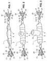
- the packer 1 shown in Figures 1 to 3 consists essentially of a rigid packer bar 2, on which the packer hose 3 and a flexible pipe lining 4 is postponed.
- Each of the two ends of the packer hose 3 is with a clamping sleeve 5 about a cylindrical connection head 6 (see. Fig. 7) stretched, so that an air-tight connection is formed.
- the connection heads 6 are in turn firmly and hermetically connected to the packer bar 2.
- left illustrated connection head 6 also takes a pressure line 7 on.
- a nozzle hose 8 is further formed, the one Has angle to the packer hose 3, which is the angle between a House connection pipe and a main pipe, which rehabilitated in the mouth area to be, corresponds. In FIGS. 1 to 3, this angle is 90 °. to Rehabilitation of the pipe connection shown in Figure 7, the angle must be 45 ° be.
- the pipe liner 4 On the packer hose 3, the pipe liner 4 is pushed, which is T-shaped is trained. It consists of a main section 9 and a Cylinder section 10, which in Figs. 1-3 an angle of 90 ° to the main section 9 has.
- the main portion 9 of the liner 4 extends parallel to the packer bar 2 and has in inflated packer hose 3 in Essentially the same diameter as the main pipe to be rehabilitated 11 (as in FIG. 7).
- the cylinder portion 10 has a house connection pipe 12 corresponding diameter.
- FIG. 1 shows the packer 1 in an evacuated state. This is about the pressure line 7 air from the inflatable shell, consisting of Packerschlauch 3 and nozzle tube 8, sucked off. The end of the nozzle tube 8 is closed and held by a rope 13 (see Figure 7), which through the Packer bar 2 passes through a winding box 14 and wound up there can be.
- a rope 13 see Figure 7
- the packer hose 3 and the lining 4 on the packer bar. 2 arranged and the packer hose 3 inflated until shown in Figure 3 Arrangement is achieved.
- the lining 4 is made of textile material and is impregnated in the inflated state with a thermosetting resin. Subsequently The rope 13 is wound in the winding box.
- the cable 13 passes through an annular alignment body 15th therethrough.
- the nozzle tube 8 is thus with the rope 13 through the ring 15 pulled therethrough into the interior of the Packerschlauchs 3.
- the upper end of the Cylinder portion 10 of the pipe liner 4 is in the area of the eversion the withdrawn neck tube 8 and stuffed in the other Retracting the neck tube with the rope 13 in the area of the eversion clamped and pulled into the interior of Packerschlauchs 3.
- the winding box 14 may further comprise a microswitch 30 (see FIG. 7), which is actuated when the cable 13 is completely pulled out of the winding box 14 is.
- the microswitch 30 triggers a signaling means 31, which is the operator the full extent of the nozzle tube 8 and thus the complete Invagination of the cylinder portion 10 in the house connection pipe 12 indicates.
- the Changing box 14 with the micro-switch 30 thus acts as a detection means for the full extension of the neck tube 8.
- Any suitable signaling means can be used as a signal light on the controller to Operate the packer or a whistle 31, which with pneumatic pressure is actuated, e.g. from the pneumatic cylinder 17 of the lifting mechanism (see below) is taken. An acoustic generated by the pipe 31 Signal gets well through the sewerage system in which the packer is used, transferred.
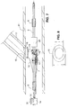
- the annular Alignment body 15 via a lifting mechanism 16 on the packer bar. 2 attached.
- the lifting mechanism 16 has a pneumatic cylinder 17 and to on both sides of the packer bar 2 a toggle lever 18. At the free ends the knee lever 18, a support frame 19 is fixed, which carries the ring 15.
- the pneumatic cylinder 17 When the pneumatic cylinder 17 is pressurized, the ring 15 moves upward via the lifting mechanism 16 and takes the in FIG dash-dotted lines drawn position.
- the upper position of the Rings 15 is shown in Figure 7 in thin lines. In this upper Position is the ring 15 in the mouth region of the house connection pipe 12. If the ring 15 for remediation of an obliquely opening into the main pipe Domestic connection pipe 12 is used, the outer contour of the ring 15th corresponding to the inner contour of the mouth of the house connection pipe 12 oval form (see Figure 8).
- each Chassis 20 consists of three guide wheels 21, the spreadable struts 22nd are connected to the packer bar 2.
- a helical spring 23 presses the struts 22 of each chassis via a common guide sleeve in the spread position. In this way, the packer bar 2 through the Landing gears 20 substantially resiliently in the middle of the main pipe 11 and rotatably guided.
- the elastically resilient chassis 20 is compressed. In this condition, it is possible to move the packer 1 axially within the main pipe to move or turn until the ring 15 into the mouth of the service pipe 12 slides in. As soon as that happens, you essentially create one positive engagement of acting as alignment body ring 15 in the Mouth of the service pipe 12. Another movement of the packer 1 is after that no longer possible.
- the outside of the ring 15 is from the connection area between packer hose 3 and nozzle hose 8 (not shown in FIG. 7) or from the connection area between the main portion 9 of the lining 4 and the cylinder portion 10 surrounded.
- This connection area the lining 4 is replaced by the annular alignment body 15 in the held for him intended end position in the region of the muzzle.
- Now can be introduced into the packer hose 3 via the pressure line 7 compressed air be, with the nozzle tube 8 with the cylinder portion 10 to the outside inverted and the recognizable in Figure 3 shape is achieved.
- Deviating from The representation in Figure 3 must in a lining of a pipe according to Figure 7, the nozzle tube 8 and the cylinder portion 10 at an angle of 45 ° Run to the packer hose 3 and main section 9 of the division 4.
- the inflatable casing 3 remains inflated until the lining 4 has hardened. Subsequently, the air from the inflatable shell, consisting from packer hose 3 and nozzle tube 8, are sucked off. After all can the packer 1 with the packer hose 3 from the cured pipe liner 4 are pulled out.
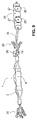
- FIG. 9 shows a representation of the packer 1 corresponding to FIG Packer 1 is about a bendable but essentially incompressible or expandable hose section 24 connected to a drive motor 25.
- On the housing of the drive motor 25 are on each side two wheels 26th arranged. At least one of the wheel axles 27 carrying a pair of wheels is drivable by the drive motor 25.
- the drive motor 25 is a pneumatic motor, preferably a piston motor driven by compressed air. To this Way, the drive motor 25 fed via the same pressure supply which directs the compressed air into the interior of the packer hose 3.
- the electronic camera 28 has preferably a CCD chip for image recording. She is either over one Data line or a wireless connection (Blue Tooth, Wireless LAN or similar) with an optical display device (screen).
- the On-screen display of the camera 28 facilitates positioning of the packer 1 in the mouth region of a house connection pipe 12.
- a light can be arranged next to or behind the camera 28 which illuminates the area captured by the camera 28.
- FIG. 7 shows near the ring 15, a heater 29.
- the heating 29 is preferably formed by an electric heating coil, the over a separating transformer is operated.
- the transformer can be used for Be designed recording different input voltages.
- Electric heating coil is very simple and less susceptible to interference.
Landscapes
- Engineering & Computer Science (AREA)
- General Engineering & Computer Science (AREA)
- Mechanical Engineering (AREA)
- Chemical & Material Sciences (AREA)
- Combustion & Propulsion (AREA)
- Health & Medical Sciences (AREA)
- Life Sciences & Earth Sciences (AREA)
- Hydrology & Water Resources (AREA)
- Public Health (AREA)
- Water Supply & Treatment (AREA)
- Lining Or Joining Of Plastics Or The Like (AREA)
- Pipe Accessories (AREA)
Priority Applications (4)
| Application Number | Priority Date | Filing Date | Title |
|---|---|---|---|
| PL04022301T PL1519100T3 (pl) | 2003-09-25 | 2004-09-20 | Urządzenie i sposób renowacji rur |
| DK08163334.9T DK1998099T3 (da) | 2003-09-25 | 2004-09-20 | Indretning til rørsanering |
| PL08163334T PL1998099T3 (pl) | 2003-09-25 | 2004-09-20 | Urządzenie do renowacji rur |
| EP08163334A EP1998099B1 (fr) | 2003-09-25 | 2004-09-20 | Appareil pour la rénovation de canalisations |
Applications Claiming Priority (4)
| Application Number | Priority Date | Filing Date | Title |
|---|---|---|---|
| DE20314914U | 2003-09-25 | ||
| DE20314914 | 2003-09-25 | ||
| DE10357059A DE10357059A1 (de) | 2003-09-25 | 2003-12-04 | Vorrichtung und Verfahren zur Rohrsanierung |
| DE10357059 | 2003-12-04 |
Related Child Applications (1)
| Application Number | Title | Priority Date | Filing Date |
|---|---|---|---|
| EP08163334A Division EP1998099B1 (fr) | 2003-09-25 | 2004-09-20 | Appareil pour la rénovation de canalisations |
Publications (2)
| Publication Number | Publication Date |
|---|---|
| EP1519100A1 true EP1519100A1 (fr) | 2005-03-30 |
| EP1519100B1 EP1519100B1 (fr) | 2008-11-05 |
Family
ID=34195784
Family Applications (1)
| Application Number | Title | Priority Date | Filing Date |
|---|---|---|---|
| EP04022301A Expired - Lifetime EP1519100B1 (fr) | 2003-09-25 | 2004-09-20 | Appareil et méthode pour la renovation de canalisations |
Country Status (3)
| Country | Link |
|---|---|
| US (2) | US7631665B2 (fr) |
| EP (1) | EP1519100B1 (fr) |
| PL (1) | PL1519100T3 (fr) |
Cited By (6)
| Publication number | Priority date | Publication date | Assignee | Title |
|---|---|---|---|---|
| US7631665B2 (en) | 2003-09-25 | 2009-12-15 | Trelleborg Pipe Seals Duisburg Gmbh | Device and method for pipeline rehabilitation |
| DE102011076850B3 (de) * | 2011-06-01 | 2012-10-04 | Trelleborg Pipe Seals Duisburg Gmbh | Inversionssteuerungsvorrichtung zur Steuerung der Inversion eines Kalibrierschlauchs |
| DE102011075404A1 (de) | 2011-05-06 | 2012-11-08 | Trelleborg Pipe Seals Duisburg Gmbh | Kalibrierschlauch |
| US9476537B2 (en) | 2011-06-27 | 2016-10-25 | Trelleborg Pipe Seals Duisburgh Gmbh | Apparatus for the rehabilitation of pipelines |
| US9657883B2 (en) | 2009-11-10 | 2017-05-23 | Repiper Ab | Apparatus and method for installing a liner in a pipe |
| US9664327B2 (en) | 2011-04-20 | 2017-05-30 | Trelleborg Pipe Seals Duisburg Gmbh | Device for rehabilitating pipelines |
Families Citing this family (31)
| Publication number | Priority date | Publication date | Assignee | Title |
|---|---|---|---|---|
| AU2007243167B2 (en) * | 2006-04-27 | 2013-02-28 | Ina Acquisition Corp. | Reinstatement of an existing connection in a lined conduit |
| WO2008052544A1 (fr) * | 2006-11-01 | 2008-05-08 | Nal Products Aps | Système et procédé pour l'installation d'un manchon de protection en forme de t |
| US8485265B2 (en) * | 2006-12-20 | 2013-07-16 | Schlumberger Technology Corporation | Smart actuation materials triggered by degradation in oilfield environments and methods of use |
| CN103899882B (zh) | 2008-02-01 | 2016-05-11 | 西部管道公司 | 在管道复原中定位和修复引入线的系统和方法 |
| KR101026177B1 (ko) * | 2008-07-18 | 2011-04-05 | 삼성중공업 주식회사 | 파이프 내부 퍼징장치 |
| US8561646B2 (en) * | 2009-12-23 | 2013-10-22 | Wpw, Llc | System and methods for multiple service line plug deployment |
| US9568139B2 (en) * | 2010-02-26 | 2017-02-14 | Trelleborg Pipe Seals Duisburg Gmbh | Lining element and method of manufacturing a lining element |
| US8820363B2 (en) * | 2010-03-24 | 2014-09-02 | Ina Acquisition Corp. | Wedge type plug and method of plugging a lateral line |
| US20120007714A1 (en) | 2010-07-07 | 2012-01-12 | Muehlin Michael | Sewer pipe repair liner with radio-frequency identification transponder and method of using same |
| US20120006440A1 (en) * | 2010-07-08 | 2012-01-12 | Lmk Enterprises, Inc. | Apparatus and method for lining a pipe junction |
| US9506596B2 (en) * | 2010-10-06 | 2016-11-29 | Lmk Technologies, Llc | Apparatus and method for repairing the junction of a sewer main and lateral pipe |
| DE102011007827B4 (de) | 2011-04-20 | 2017-10-19 | Trelleborg Pipe Seals Duisburg Gmbh | Fahrvorrichtung für eine Vorrichtung zur Sanierung von Rohrleitungen und eine solche Vorrichtung |
| US9341302B2 (en) | 2012-10-16 | 2016-05-17 | Lmk Technologies, Llc | Means and method for lining a pipe |
| US8925590B2 (en) * | 2013-02-07 | 2015-01-06 | King Fahd University Of Petroleum And Minerals | Pipeline leak detection and repair device |
| US9841135B2 (en) * | 2013-05-29 | 2017-12-12 | Nal Products Aps | Heatable packer |
| DE102014107672A1 (de) | 2014-05-30 | 2015-12-03 | Trelleborg Pipe Seals Duisburg Gmbh | Auskleidungselement zur Sanierung einer Rohrleitung |
| DE102014112254B4 (de) | 2014-08-26 | 2021-02-04 | Trelleborg Pipe Seals Duisburg Gmbh | Verfahren zur Sanierung einer Rohrleitung |
| GB2549238A (en) * | 2015-02-23 | 2017-10-11 | Source 1 Env Llc | Pipe repair apparatus and method |
| NO20160491A1 (no) * | 2016-03-29 | 2017-09-11 | Olimb Group As | System og fremgangsmåte for gravefri renovasjon av anboringsklammer |
| CA2974678A1 (fr) * | 2016-07-28 | 2018-01-28 | BLD Services, LLC | Systemes de revetement interieur de tuyau et methodes d'utilisation |
| CN107366798A (zh) * | 2017-08-01 | 2017-11-21 | 武汉中仪物联技术股份有限公司 | 紫外光固化管道修复机器人及系统 |
| US10907760B2 (en) * | 2018-01-25 | 2021-02-02 | Picote Solutions Oy Ltd. | Installation device |
| DE102018115678A1 (de) * | 2018-06-28 | 2020-01-02 | Christoph Wenk | Dichtvorrichtung und zugehörige Innenmanschette |
| DE102019100276A1 (de) * | 2018-08-22 | 2020-02-27 | DCF Holding GmbH | Verfahren und Vorrichtung zur Sanierung eines Rohrabschnitts eines Rohrleitungssystems |
| US11079055B2 (en) | 2018-10-30 | 2021-08-03 | Ina Acquisition Corp. | Fitting for connecting a main pipe liner to a branch conduit |
| CA3118286A1 (fr) | 2018-10-30 | 2020-05-07 | Ina Acquisition Corp. | Raccord pour le raccordement d'un chemisage de tuyau principal a un conduit de derivation |
| WO2020113125A1 (fr) | 2018-11-30 | 2020-06-04 | Ina Acqusition Corp. | Procédés, systèmes et appareil destinés à être utilisés dans des tuyaux principaux raccordés à des conduits de ramification |
| WO2021179054A1 (fr) * | 2020-03-13 | 2021-09-16 | Ibco Pty Ltd | Manchon gonflable et procédé pour sa fabrication |
| SE545096C2 (en) * | 2021-05-12 | 2023-03-28 | Peanta Invent Ab | Pipe lining tool |
| CN114233976B (zh) * | 2021-12-24 | 2022-08-26 | 中国地质大学(武汉) | 一种自动一体化非开挖管道注浆系统和注浆方法 |
| CN115059830B (zh) * | 2022-08-18 | 2022-11-08 | 杭州天意达市政工程有限公司 | 一种管道非开挖修复装置 |
Citations (11)
| Publication number | Priority date | Publication date | Assignee | Title |
|---|---|---|---|---|
| GB2150050A (en) * | 1983-11-22 | 1985-06-26 | Spracon International Limited | Pipe coating apparatus |
| GB2192441A (en) * | 1986-07-11 | 1988-01-13 | Tracey Stephen | Lining a duct |
| US5207031A (en) * | 1989-04-26 | 1993-05-04 | Kresten Gammelgaard | Apparatus for use in renovation of tube systems, in particular sewer tube systems |
| DE4400742A1 (de) * | 1994-01-13 | 1995-07-20 | Jt Elektronik Gmbh | Vorrichtung zur Sanierung von Hausanschlüssen |
| EP0683348A2 (fr) * | 1994-05-17 | 1995-11-22 | D.T.I. Dr. TRIPPE INGENIEURGES. mbH. | Dispositif pour l'étanchement la paroi d'une canalisation au niveau des jonctions entre canalisations principales et branchements latéraux |
| US5659915A (en) * | 1995-10-13 | 1997-08-26 | United States Department Of Energy | Off gas film cooler cleaner |
| EP0823579A1 (fr) * | 1996-08-09 | 1998-02-11 | Sade- Compagnie Generale De Travaux D' Hydraulique Societe Anonyme | Dispositif pour le chemisage d'un branchement, procédé de chemisage et gaine de chemisage |
| GB2320076A (en) * | 1996-12-05 | 1998-06-10 | Tube Tech Limited | Feed mechanism |
| US5927341A (en) * | 1993-09-25 | 1999-07-27 | Insituform (Netherlands) B.V. | Lining of "Tees" and "Wyes" in pipelines or passageways |
| US5950682A (en) * | 1994-08-19 | 1999-09-14 | Lmk Enterprises, Inc. | Apparatus and method for repairing the junction of a sewer main line and lateral |
| US6484757B1 (en) * | 2002-03-19 | 2002-11-26 | Liqui-Force Sewer Services Inc. | Method and device for lining a lateral sewer pipe |
Family Cites Families (26)
| Publication number | Priority date | Publication date | Assignee | Title |
|---|---|---|---|---|
| US3718978A (en) * | 1970-10-16 | 1973-03-06 | Koevering B Van | Pipeline survey vehicle |
| US4982490A (en) * | 1986-07-11 | 1991-01-08 | Stephen Tracey | Method of lining a fluid conduit |
| CH682945A5 (de) * | 1989-12-01 | 1993-12-15 | Sika Robotics Ag | Ferngesteuerter Schalungseinbau in nicht begehbaren Rohrverzweigungen und Einmündungen. |
| US5340160A (en) * | 1989-11-21 | 1994-08-23 | Wavin B.V. | Thermoplastic saddle in two parts for repairing or renovating a pipe line with branch pipe and repaired or renovated pipe with a saddle |
| GB9009073D0 (en) * | 1990-04-23 | 1990-06-20 | Insituform Group Ltd | Improvements relating to the lining of pipelines or passageways |
| JP2554411B2 (ja) * | 1991-05-31 | 1996-11-13 | 株式会社ゲット | 枝管ライニング材及びその製造方法 |
| US5674030A (en) * | 1991-08-27 | 1997-10-07 | Sika Equipment Ag. | Device and method for repairing building branch lines in inacessible sewer mains |
| GB9127315D0 (en) * | 1991-12-23 | 1992-02-19 | Insituform Group Ltd | Improvements relating to the lining of pipelines and passageways |
| DE4207038C2 (de) | 1992-03-06 | 1994-12-01 | Mueller Hans | Packer zum Auskleiden des Übergangsbereichs zwischen einem Awasserhauptrohr und einem einmündenden Hausanschlußrohr |
| JP2530553B2 (ja) * | 1993-03-23 | 1996-09-04 | 株式会社湘南合成樹脂製作所 | 枝管ライニング工法 |
| US5451284A (en) * | 1992-12-25 | 1995-09-19 | Nippon Kokan Koji Kabushiki Kaisha | Self-mobile work vehicle moveable through pipeline and method and apparatus for lining interconnecting branch pipe using the vehicle |
| DE4418331C2 (de) | 1994-05-26 | 1996-08-14 | Klaus Dieter Zawisla Gmbh | Verfahren und Vorrichtung zum Verschließen einer in eine Hauptleitung mündenden Zweigleitung |
| JP2605220B2 (ja) * | 1994-07-05 | 1997-04-30 | 株式会社湘南合成樹脂製作所 | 枝管ライニング工法 |
| US5527133A (en) * | 1994-08-17 | 1996-06-18 | Csillag; Robert | Tool for a sewer robot |
| US5794663A (en) * | 1994-08-19 | 1998-08-18 | Lmk Enterprises | Apparatus for repairing a pipeline and method for using same |
| JP2667796B2 (ja) * | 1995-07-07 | 1997-10-27 | 株式会社湘南合成樹脂製作所 | 管ライニング工法 |
| US5859915A (en) * | 1997-04-30 | 1999-01-12 | American Technology Corporation | Lighted enhanced bullhorn |
| US6068725A (en) * | 1997-11-26 | 2000-05-30 | Insituform (Netherlands) B.V. | Method of installation of a flexible cured in place lateral seal in an existing main pipeline |
| US6029726A (en) * | 1997-11-26 | 2000-02-29 | Insituform (Netherlands) B.V. | Apparatus for installing a flexible cured in place lateral seal in an existing main pipeline |
| DE29802675U1 (de) | 1998-02-17 | 1998-08-06 | KMG Kanal-Müller-Gruppe Mitte GmbH & Co KG, 32816 Schieder-Schwalenberg | Vorrichtung zum Einbringen eines Auskleideschlauches vom Hauptabwasserkanal aus in einen Hausanschlußkanal |
| JP3971013B2 (ja) * | 1998-02-27 | 2007-09-05 | 株式会社湘南合成樹脂製作所 | 枝管ライニング工法 |
| US6039079A (en) * | 1998-07-17 | 2000-03-21 | Lmk Enterprises, Inc. | Apparatus and method for repairing the junction of a sewer main line and lateral pipe |
| WO2001061236A2 (fr) | 2000-02-02 | 2001-08-23 | Ihc Rehabilitation Products | Appareil, procedes et chemises de reparation de conduits |
| US7135087B2 (en) * | 2001-02-02 | 2006-11-14 | Verline Inc. | Apparatus and method for the repair and stabilization of underground pipes |
| KR100487881B1 (ko) * | 2001-12-12 | 2005-05-03 | 동도기공 주식회사 | 노후 보수관의 가지관용 라이닝 장치 |
| EP1519100B1 (fr) | 2003-09-25 | 2008-11-05 | Trelleborg epros GmbH | Appareil et méthode pour la renovation de canalisations |
-
2004
- 2004-09-20 EP EP04022301A patent/EP1519100B1/fr not_active Expired - Lifetime
- 2004-09-20 PL PL04022301T patent/PL1519100T3/pl unknown
- 2004-09-22 US US10/947,503 patent/US7631665B2/en active Active
-
2009
- 2009-10-30 US US12/589,982 patent/US8499798B2/en not_active Expired - Fee Related
Patent Citations (11)
| Publication number | Priority date | Publication date | Assignee | Title |
|---|---|---|---|---|
| GB2150050A (en) * | 1983-11-22 | 1985-06-26 | Spracon International Limited | Pipe coating apparatus |
| GB2192441A (en) * | 1986-07-11 | 1988-01-13 | Tracey Stephen | Lining a duct |
| US5207031A (en) * | 1989-04-26 | 1993-05-04 | Kresten Gammelgaard | Apparatus for use in renovation of tube systems, in particular sewer tube systems |
| US5927341A (en) * | 1993-09-25 | 1999-07-27 | Insituform (Netherlands) B.V. | Lining of "Tees" and "Wyes" in pipelines or passageways |
| DE4400742A1 (de) * | 1994-01-13 | 1995-07-20 | Jt Elektronik Gmbh | Vorrichtung zur Sanierung von Hausanschlüssen |
| EP0683348A2 (fr) * | 1994-05-17 | 1995-11-22 | D.T.I. Dr. TRIPPE INGENIEURGES. mbH. | Dispositif pour l'étanchement la paroi d'une canalisation au niveau des jonctions entre canalisations principales et branchements latéraux |
| US5950682A (en) * | 1994-08-19 | 1999-09-14 | Lmk Enterprises, Inc. | Apparatus and method for repairing the junction of a sewer main line and lateral |
| US5659915A (en) * | 1995-10-13 | 1997-08-26 | United States Department Of Energy | Off gas film cooler cleaner |
| EP0823579A1 (fr) * | 1996-08-09 | 1998-02-11 | Sade- Compagnie Generale De Travaux D' Hydraulique Societe Anonyme | Dispositif pour le chemisage d'un branchement, procédé de chemisage et gaine de chemisage |
| GB2320076A (en) * | 1996-12-05 | 1998-06-10 | Tube Tech Limited | Feed mechanism |
| US6484757B1 (en) * | 2002-03-19 | 2002-11-26 | Liqui-Force Sewer Services Inc. | Method and device for lining a lateral sewer pipe |
Cited By (7)
| Publication number | Priority date | Publication date | Assignee | Title |
|---|---|---|---|---|
| US7631665B2 (en) | 2003-09-25 | 2009-12-15 | Trelleborg Pipe Seals Duisburg Gmbh | Device and method for pipeline rehabilitation |
| US9657883B2 (en) | 2009-11-10 | 2017-05-23 | Repiper Ab | Apparatus and method for installing a liner in a pipe |
| US9664327B2 (en) | 2011-04-20 | 2017-05-30 | Trelleborg Pipe Seals Duisburg Gmbh | Device for rehabilitating pipelines |
| DE102011075404A1 (de) | 2011-05-06 | 2012-11-08 | Trelleborg Pipe Seals Duisburg Gmbh | Kalibrierschlauch |
| DE102011076850B3 (de) * | 2011-06-01 | 2012-10-04 | Trelleborg Pipe Seals Duisburg Gmbh | Inversionssteuerungsvorrichtung zur Steuerung der Inversion eines Kalibrierschlauchs |
| WO2012163700A2 (fr) | 2011-06-01 | 2012-12-06 | Trelleborg Pipe Seals Duisburg Gmbh | Appareil de commande d'inversion pour commander l'inversion d'un tuyau d'étalonnage |
| US9476537B2 (en) | 2011-06-27 | 2016-10-25 | Trelleborg Pipe Seals Duisburgh Gmbh | Apparatus for the rehabilitation of pipelines |
Also Published As
| Publication number | Publication date |
|---|---|
| US20100043903A1 (en) | 2010-02-25 |
| US8499798B2 (en) | 2013-08-06 |
| PL1519100T3 (pl) | 2009-06-30 |
| EP1519100B1 (fr) | 2008-11-05 |
| US7631665B2 (en) | 2009-12-15 |
| US20050092382A1 (en) | 2005-05-05 |
Similar Documents
| Publication | Publication Date | Title |
|---|---|---|
| EP1519100B1 (fr) | Appareil et méthode pour la renovation de canalisations | |
| DE69519130T2 (de) | Verfahren zur Beschichtung einer Abzweigleitung eines unterirdischen Rohres | |
| DE69300605T2 (de) | Vorrichtung zur In-situ-Sanierung von nichtbegehbaren Rohrleitungen oder Kanälen und Verfahren zur Wiederherstellung mit Hilfe dieser Vorrichtung. | |
| DE2805351A1 (de) | Geraet zum entfernen von gegenstaenden aus menschlichen koerperdurchgaengen | |
| DE4138240A1 (de) | Medizinisches instrument | |
| DE3546417A1 (de) | Verfahren und vorrichtung zur sanierung insbesondere erdverlegter rohrleitungen | |
| DE69003500T2 (de) | Verfahren zur reparatur einer leitung sowie vorrichtung zur verwendung dazu. | |
| DE4022103C2 (fr) | ||
| DE102015200149B4 (de) | Bogengängiger Sanierungspacker zur Rohr- oder Kanalsanierung | |
| EP4235010A1 (fr) | Packer pour la réhabilitation de tuyaux et de canalisations | |
| DE102011013597B4 (de) | Vorrichtung und Verfahren zum Setzen einer Hutmanschette in eine Kanalabzweigung | |
| EP1998099B1 (fr) | Appareil pour la rénovation de canalisations | |
| DE4404712A1 (de) | Verfahren zum Ausbau eines Erdkerns aus einem grabenlos verlegten Rohr und Molch zur Durchführung des Verfahrens | |
| DE212007000059U1 (de) | Wiederverwendbare Stülpmanschetten-Baugruppe zur Umstülpung vor Ort aushärtender Einsätze | |
| DE19702649C2 (de) | Vorrichtung zur Sanierung von Kanalrohren | |
| DE4417076C2 (de) | Vorrichtung zum Abdichten von Kanalwandungen im Bereich des Anschlusses eines Nebenkanals an einen Hauptkanal | |
| DE102008010167B4 (de) | Vorrichtung und Verfahren zum Härten von harzgetränkten Faserschläuchen | |
| DE4213898A1 (de) | Vorrichtung zum reparieren unterirdisch verlegter rohrleitungen | |
| DE102011007826B4 (de) | Vorrichtung zur Sanierung von Rohrleitungen | |
| DE102006034652B4 (de) | Packer für die Rohr- und Kanalsanierung | |
| DE4400742A1 (de) | Vorrichtung zur Sanierung von Hausanschlüssen | |
| EP1457728B1 (fr) | Dispositif de rénovation d'une conduite de raccordement domestique depuis une conduite principale | |
| DE102014117442B3 (de) | Verfahren zum Einziehen eines Neurohres in ein Altrohr und zur Durchführung des Verfahrens geeignete Vorrichtung | |
| DE19640697A1 (de) | Vorrichtung zum Transport und zur Manipulation eines Werkzeugs in einem Abwasserrohr eines Kanalnetzes | |
| EP3614032B1 (fr) | Dispositif et procédé d'assainissement d'une section de tuyau d'un système de tuyauterie |
Legal Events
| Date | Code | Title | Description |
|---|---|---|---|
| PUAI | Public reference made under article 153(3) epc to a published international application that has entered the european phase |
Free format text: ORIGINAL CODE: 0009012 |
|
| AK | Designated contracting states |
Kind code of ref document: A1 Designated state(s): AT BE BG CH CY CZ DE DK EE ES FI FR GB GR HU IE IT LI LU MC NL PL PT RO SE SI SK TR |
|
| AX | Request for extension of the european patent |
Extension state: AL HR LT LV MK |
|
| 17P | Request for examination filed |
Effective date: 20050929 |
|
| AKX | Designation fees paid |
Designated state(s): AT BE BG CH CY CZ DE DK EE ES FI FR GB GR HU IE IT LI LU MC NL PL PT RO SE SI SK TR |
|
| GRAP | Despatch of communication of intention to grant a patent |
Free format text: ORIGINAL CODE: EPIDOSNIGR1 |
|
| RAP1 | Party data changed (applicant data changed or rights of an application transferred) |
Owner name: TRELLEBORG EPROS GMBH |
|
| GRAS | Grant fee paid |
Free format text: ORIGINAL CODE: EPIDOSNIGR3 |
|
| GRAA | (expected) grant |
Free format text: ORIGINAL CODE: 0009210 |
|
| AK | Designated contracting states |
Kind code of ref document: B1 Designated state(s): AT BE BG CH CY CZ DE DK EE ES FI FR GB GR HU IE IT LI LU MC NL PL PT RO SE SI SK TR |
|
| REG | Reference to a national code |
Ref country code: GB Ref legal event code: FG4D Free format text: NOT ENGLISH |
|
| REG | Reference to a national code |
Ref country code: CH Ref legal event code: EP |
|
| REG | Reference to a national code |
Ref country code: IE Ref legal event code: FG4D Free format text: LANGUAGE OF EP DOCUMENT: GERMAN |
|
| REF | Corresponds to: |
Ref document number: 502004008391 Country of ref document: DE Date of ref document: 20081218 Kind code of ref document: P |
|
| REG | Reference to a national code |
Ref country code: CH Ref legal event code: NV Representative=s name: MICHELI & CIE SA |
|
| REG | Reference to a national code |
Ref country code: SE Ref legal event code: TRGR |
|
| REG | Reference to a national code |
Ref country code: DK Ref legal event code: T3 |
|
| PG25 | Lapsed in a contracting state [announced via postgrant information from national office to epo] |
Ref country code: ES Free format text: LAPSE BECAUSE OF FAILURE TO SUBMIT A TRANSLATION OF THE DESCRIPTION OR TO PAY THE FEE WITHIN THE PRESCRIBED TIME-LIMIT Effective date: 20090216 |
|
| PG25 | Lapsed in a contracting state [announced via postgrant information from national office to epo] |
Ref country code: SI Free format text: LAPSE BECAUSE OF FAILURE TO SUBMIT A TRANSLATION OF THE DESCRIPTION OR TO PAY THE FEE WITHIN THE PRESCRIBED TIME-LIMIT Effective date: 20081105 Ref country code: FI Free format text: LAPSE BECAUSE OF FAILURE TO SUBMIT A TRANSLATION OF THE DESCRIPTION OR TO PAY THE FEE WITHIN THE PRESCRIBED TIME-LIMIT Effective date: 20081105 |
|
| REG | Reference to a national code |
Ref country code: PL Ref legal event code: T3 |
|
| PG25 | Lapsed in a contracting state [announced via postgrant information from national office to epo] |
Ref country code: RO Free format text: LAPSE BECAUSE OF FAILURE TO SUBMIT A TRANSLATION OF THE DESCRIPTION OR TO PAY THE FEE WITHIN THE PRESCRIBED TIME-LIMIT Effective date: 20081105 Ref country code: BG Free format text: LAPSE BECAUSE OF FAILURE TO SUBMIT A TRANSLATION OF THE DESCRIPTION OR TO PAY THE FEE WITHIN THE PRESCRIBED TIME-LIMIT Effective date: 20090205 Ref country code: EE Free format text: LAPSE BECAUSE OF FAILURE TO SUBMIT A TRANSLATION OF THE DESCRIPTION OR TO PAY THE FEE WITHIN THE PRESCRIBED TIME-LIMIT Effective date: 20081105 |
|
| PG25 | Lapsed in a contracting state [announced via postgrant information from national office to epo] |
Ref country code: PT Free format text: LAPSE BECAUSE OF FAILURE TO SUBMIT A TRANSLATION OF THE DESCRIPTION OR TO PAY THE FEE WITHIN THE PRESCRIBED TIME-LIMIT Effective date: 20090406 |
|
| PLBE | No opposition filed within time limit |
Free format text: ORIGINAL CODE: 0009261 |
|
| STAA | Information on the status of an ep patent application or granted ep patent |
Free format text: STATUS: NO OPPOSITION FILED WITHIN TIME LIMIT |
|
| PG25 | Lapsed in a contracting state [announced via postgrant information from national office to epo] |
Ref country code: SK Free format text: LAPSE BECAUSE OF FAILURE TO SUBMIT A TRANSLATION OF THE DESCRIPTION OR TO PAY THE FEE WITHIN THE PRESCRIBED TIME-LIMIT Effective date: 20081105 |
|
| 26N | No opposition filed |
Effective date: 20090806 |
|
| REG | Reference to a national code |
Ref country code: CH Ref legal event code: PFA Owner name: TRELLEBORG PIPE SEALS DUISBURG GMBH Free format text: TRELLEBORG EPROS GMBH#DR.-ALFRED-HERRHAUSEN-ALLEE 20D#47228 DUISBURG (DE) -TRANSFER TO- TRELLEBORG PIPE SEALS DUISBURG GMBH#DR.-ALFRED-HERRHAUSEN-ALLEE 20D#47228 DUISBURG (DE) |
|
| REG | Reference to a national code |
Ref country code: CH Ref legal event code: PCOW Free format text: TRELLEBORG PIPE SEALS DUISBURG GMBH;DR.-ALFRED-HERRHAUSEN-ALLEE 36;47228 DUISBURG (DE) |
|
| NLT1 | Nl: modifications of names registered in virtue of documents presented to the patent office pursuant to art. 16 a, paragraph 1 |
Owner name: TRELLEBORG PIPE SEALS DUISBURG GMBH |
|
| BERE | Be: lapsed |
Owner name: TRELLEBORG EPROS G.M.B.H. Effective date: 20090930 |
|
| REG | Reference to a national code |
Ref country code: FR Ref legal event code: CD |
|
| PG25 | Lapsed in a contracting state [announced via postgrant information from national office to epo] |
Ref country code: CZ Free format text: LAPSE BECAUSE OF NON-PAYMENT OF DUE FEES Effective date: 20090920 Ref country code: MC Free format text: LAPSE BECAUSE OF NON-PAYMENT OF DUE FEES Effective date: 20090930 |
|
| PG25 | Lapsed in a contracting state [announced via postgrant information from national office to epo] |
Ref country code: BE Free format text: LAPSE BECAUSE OF NON-PAYMENT OF DUE FEES Effective date: 20090930 |
|
| PG25 | Lapsed in a contracting state [announced via postgrant information from national office to epo] |
Ref country code: GR Free format text: LAPSE BECAUSE OF FAILURE TO SUBMIT A TRANSLATION OF THE DESCRIPTION OR TO PAY THE FEE WITHIN THE PRESCRIBED TIME-LIMIT Effective date: 20090206 |
|
| PG25 | Lapsed in a contracting state [announced via postgrant information from national office to epo] |
Ref country code: LU Free format text: LAPSE BECAUSE OF NON-PAYMENT OF DUE FEES Effective date: 20090920 |
|
| PG25 | Lapsed in a contracting state [announced via postgrant information from national office to epo] |
Ref country code: HU Free format text: LAPSE BECAUSE OF FAILURE TO SUBMIT A TRANSLATION OF THE DESCRIPTION OR TO PAY THE FEE WITHIN THE PRESCRIBED TIME-LIMIT Effective date: 20090506 |
|
| PG25 | Lapsed in a contracting state [announced via postgrant information from national office to epo] |
Ref country code: CY Free format text: LAPSE BECAUSE OF FAILURE TO SUBMIT A TRANSLATION OF THE DESCRIPTION OR TO PAY THE FEE WITHIN THE PRESCRIBED TIME-LIMIT Effective date: 20081105 |
|
| PGFP | Annual fee paid to national office [announced via postgrant information from national office to epo] |
Ref country code: CH Payment date: 20110926 Year of fee payment: 8 Ref country code: DK Payment date: 20110926 Year of fee payment: 8 |
|
| PGFP | Annual fee paid to national office [announced via postgrant information from national office to epo] |
Ref country code: SE Payment date: 20120920 Year of fee payment: 9 Ref country code: IE Payment date: 20120918 Year of fee payment: 9 Ref country code: GB Payment date: 20120920 Year of fee payment: 9 |
|
| PGFP | Annual fee paid to national office [announced via postgrant information from national office to epo] |
Ref country code: PL Payment date: 20120907 Year of fee payment: 9 Ref country code: TR Payment date: 20120919 Year of fee payment: 9 |
|
| PGFP | Annual fee paid to national office [announced via postgrant information from national office to epo] |
Ref country code: IT Payment date: 20120925 Year of fee payment: 9 |
|
| PGFP | Annual fee paid to national office [announced via postgrant information from national office to epo] |
Ref country code: NL Payment date: 20120920 Year of fee payment: 9 Ref country code: FR Payment date: 20121008 Year of fee payment: 9 |
|
| PGFP | Annual fee paid to national office [announced via postgrant information from national office to epo] |
Ref country code: AT Payment date: 20120919 Year of fee payment: 9 |
|
| REG | Reference to a national code |
Ref country code: NL Ref legal event code: V1 Effective date: 20140401 |
|
| REG | Reference to a national code |
Ref country code: SE Ref legal event code: EUG |
|
| PG25 | Lapsed in a contracting state [announced via postgrant information from national office to epo] |
Ref country code: SE Free format text: LAPSE BECAUSE OF NON-PAYMENT OF DUE FEES Effective date: 20130921 |
|
| REG | Reference to a national code |
Ref country code: CH Ref legal event code: PL |
|
| REG | Reference to a national code |
Ref country code: DK Ref legal event code: EBP Effective date: 20130930 |
|
| REG | Reference to a national code |
Ref country code: AT Ref legal event code: MM01 Ref document number: 413560 Country of ref document: AT Kind code of ref document: T Effective date: 20130920 |
|
| GBPC | Gb: european patent ceased through non-payment of renewal fee |
Effective date: 20130920 |
|
| REG | Reference to a national code |
Ref country code: FR Ref legal event code: ST Effective date: 20140530 |
|
| REG | Reference to a national code |
Ref country code: IE Ref legal event code: MM4A |
|
| PG25 | Lapsed in a contracting state [announced via postgrant information from national office to epo] |
Ref country code: LI Free format text: LAPSE BECAUSE OF NON-PAYMENT OF DUE FEES Effective date: 20130930 Ref country code: IE Free format text: LAPSE BECAUSE OF NON-PAYMENT OF DUE FEES Effective date: 20130920 Ref country code: GB Free format text: LAPSE BECAUSE OF NON-PAYMENT OF DUE FEES Effective date: 20130920 Ref country code: CH Free format text: LAPSE BECAUSE OF NON-PAYMENT OF DUE FEES Effective date: 20130930 |
|
| PG25 | Lapsed in a contracting state [announced via postgrant information from national office to epo] |
Ref country code: IT Free format text: LAPSE BECAUSE OF NON-PAYMENT OF DUE FEES Effective date: 20130920 Ref country code: NL Free format text: LAPSE BECAUSE OF NON-PAYMENT OF DUE FEES Effective date: 20140401 Ref country code: FR Free format text: LAPSE BECAUSE OF NON-PAYMENT OF DUE FEES Effective date: 20130930 Ref country code: AT Free format text: LAPSE BECAUSE OF NON-PAYMENT OF DUE FEES Effective date: 20130920 |
|
| PG25 | Lapsed in a contracting state [announced via postgrant information from national office to epo] |
Ref country code: DK Free format text: LAPSE BECAUSE OF NON-PAYMENT OF DUE FEES Effective date: 20130930 |
|
| PG25 | Lapsed in a contracting state [announced via postgrant information from national office to epo] |
Ref country code: PL Free format text: LAPSE BECAUSE OF NON-PAYMENT OF DUE FEES Effective date: 20130920 |
|
| REG | Reference to a national code |
Ref country code: PL Ref legal event code: LAPE |
|
| PG25 | Lapsed in a contracting state [announced via postgrant information from national office to epo] |
Ref country code: TR Free format text: LAPSE BECAUSE OF NON-PAYMENT OF DUE FEES Effective date: 20130920 |
|
| PGFP | Annual fee paid to national office [announced via postgrant information from national office to epo] |
Ref country code: DE Payment date: 20210929 Year of fee payment: 18 |
|
| REG | Reference to a national code |
Ref country code: DE Ref legal event code: R119 Ref document number: 502004008391 Country of ref document: DE |
|
| PG25 | Lapsed in a contracting state [announced via postgrant information from national office to epo] |
Ref country code: DE Free format text: LAPSE BECAUSE OF NON-PAYMENT OF DUE FEES Effective date: 20230401 |