EP0683356A2 - Procédé de fonctionnement d'une chambre de combustion - Google Patents
Procédé de fonctionnement d'une chambre de combustion Download PDFInfo
- Publication number
- EP0683356A2 EP0683356A2 EP95810290A EP95810290A EP0683356A2 EP 0683356 A2 EP0683356 A2 EP 0683356A2 EP 95810290 A EP95810290 A EP 95810290A EP 95810290 A EP95810290 A EP 95810290A EP 0683356 A2 EP0683356 A2 EP 0683356A2
- Authority
- EP
- European Patent Office
- Prior art keywords
- fuel
- zone
- combustion chamber
- lances
- combustion
- Prior art date
- Legal status (The legal status is an assumption and is not a legal conclusion. Google has not performed a legal analysis and makes no representation as to the accuracy of the status listed.)
- Granted
Links
Images
Classifications
-
- F—MECHANICAL ENGINEERING; LIGHTING; HEATING; WEAPONS; BLASTING
- F23—COMBUSTION APPARATUS; COMBUSTION PROCESSES
- F23C—METHODS OR APPARATUS FOR COMBUSTION USING FLUID FUEL OR SOLID FUEL SUSPENDED IN A CARRIER GAS OR AIR
- F23C5/00—Disposition of burners with respect to the combustion chamber or to one another; Mounting of burners in combustion apparatus
-
- F—MECHANICAL ENGINEERING; LIGHTING; HEATING; WEAPONS; BLASTING
- F23—COMBUSTION APPARATUS; COMBUSTION PROCESSES
- F23D—BURNERS
- F23D23/00—Assemblies of two or more burners
-
- F—MECHANICAL ENGINEERING; LIGHTING; HEATING; WEAPONS; BLASTING
- F23—COMBUSTION APPARATUS; COMBUSTION PROCESSES
- F23R—GENERATING COMBUSTION PRODUCTS OF HIGH PRESSURE OR HIGH VELOCITY, e.g. GAS-TURBINE COMBUSTION CHAMBERS
- F23R3/00—Continuous combustion chambers using liquid or gaseous fuel
- F23R3/28—Continuous combustion chambers using liquid or gaseous fuel characterised by the fuel supply
Definitions
- the present invention relates to a method according to the preamble of claim 1. It also relates to a combustion chamber for carrying out the method.
- the invention seeks to remedy this.
- the object of the invention is to minimize, in particular, the CO and UHC emissions in the critical range between auto-ignition and a temperature of approximately 1100 ° C. in a method and a combustion chamber of the type mentioned at the outset .
- the burners should be divided into at least two groups.
- the individual groups are run in series from the auto-ignition point to at least 1100 ° C.
- the group of burners used is supplied on average with a larger amount of fuel during the starting phase; the individual burners can thus be operated more stably. If all burner groups up to a temperature level of approx. 1100 ° C have been retightened, they are then raised in parallel from this temperature level to the desired operating temperature.
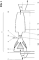
- annular combustion chamber 1 shows, as can be seen from the shaft axis 16, an annular combustion chamber 1, which essentially has the shape of a coherent annular or quasi-annular cylinder.
- a combustion chamber can also consist of a number of axially, quasi-axially or helically arranged and individually closed combustion chambers.
- Such ring combustion chambers are excellently suited to be operated as self-igniting combustion chambers which are placed in the flow direction between two turbines mounted on a shaft. If such an annular combustion chamber 1 is operated on self-ignition, the upstream turbine 2 is only designed for partial relaxation of the hot gases 3, so that the exhaust gases 4 downstream of this turbine 2 still flow into the inflow zone 5 of the annular combustion chamber 1 at a very high temperature.
- This inflow zone 5 is equipped on the inside and in the circumferential direction of the channel wall 6 with a series of vortex-generating elements 100, hereinafter only called vortex generators.
- the exhaust gases 4 are swirled by the vortex generators 100 such that no recirculation areas occur in the wake of the vortex generators 100 mentioned in the subsequent premixing section 7.
- this premixing section 7 which is designed as a Venturi channel, a plurality of fuel lances 8 are arranged, which take over the supply of a fuel 9 and supporting air 10. These fuel lances 8 are discussed in more detail below. These media can be supplied to the individual fuel lances 8, for example, via a ring line (not shown).
- the swirl flow triggered by the vortex generators 100 provides for a large-scale distribution of the introduced fuel 9, and possibly also the admixed supporting air 10. Furthermore, the swirl flow ensures a homogenization of the mixture of combustion air and fuel.
- the fuel 9 injected into the exhaust gases 4 by the fuel lance 8 triggers self-ignition if these exhaust gases 4 have the specific temperature which the fuel-dependent auto-ignition is capable of triggering. If the ring combustion chamber 1 is operated with a gaseous fuel, a temperature of the exhaust gases 4 above approx. 850 ° C. must be present for the initiation of self-ignition. With such a combustion, as already appreciated above, there is a risk of a flashback. This problem is remedied by, on the one hand, designing the premixing zone 7 as a venturi channel and, on the other hand, disposing the injection of the fuel 9 in the region of the largest constriction within the premixing zone 7.
- a combustion zone 11 follows the relatively short premixing zone 7.
- the transition between the two zones is formed by a radial cross-sectional jump 12, which initially induces the flow cross-section of the combustion zone 11.
- the cross-sectional jump 12 is also a flame front. In order to prevent the flame from reigniting into the interior of the premixing zone 7, the flame front must be kept stable.
- the vortex generators 100 are designed such that no recirculation takes place in the premixing zone 7; only after the sudden widening of the cross section is the burst of the swirl flow desired.
- the swirl flow supports the rapid re-application of the flow behind the cross-sectional jump 12, so that a high burn-out with a short overall length can be achieved by utilizing the volume of the combustion zone 11 as fully as possible.
- a flow-like edge zone is formed during operation, in which vortex detachments occur due to the prevailing negative pressure, which then lead to stabilization of the flame front.
- the exhaust gases 4 processed into combustion gases 11 into hot gases 14 subsequently act on a further turbine 14 acting downstream.
- the exhaust gases 15 can then be used to operate a steam cycle, in which case the system is a combination system.
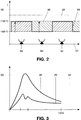
- FIG. 2 shows a diagram in which the stepped mode of operation of the burners can be seen during the starting phase.
- the abscissa 17 intends to symbolize the development of the burners arranged next to one another, while the ordinate 18 shows the first temperature levels approached during the starting phase.
- the staged procedure consists in that the burners, ie the fuel lances from FIG. 1, are supplied with fuel in series during the starting phase.
- the fuel lances 8a, 8c, etc. are put into operation and are first brought up to approximately 1100 ° C.
- the remaining fuel lances 8b, 8d, etc. are also drawn up to the above-mentioned temperature level of approx. 1100 ° C.
- this driving style has the additional advantage that CO and UHC emissions in particular can be significantly reduced in the critical range between 1000 ° C and 1100 ° C.
- the staged driving style during the starting phase is not limited to 2 groups of burners.
- the abscissa 22 shows the load range, zero being the temperature level at which the self-ignition of the mixture takes place, that is to say from about 850 ° C. in our case.
- the ordinate 23 shows the degree of pollutant emissions.
- Curve 24 shows the course of the pollutant emissions in a conventional, non-stepped driving style. The tip symbolizes the CO and UHC emissions in the interval between approx. 1000 ° C and approx. 1100 ° C.
- the stepped driving style is different, as curve 25 shows.
- a two-hump curve is recognizable here, corresponding to the stepped mode of operation with two burner groups.
- the staged driving style can achieve emission values that are more than half smaller than the conventional driving style.
Landscapes
- Engineering & Computer Science (AREA)
- Chemical & Material Sciences (AREA)
- Combustion & Propulsion (AREA)
- Mechanical Engineering (AREA)
- General Engineering & Computer Science (AREA)
- Combustion Of Fluid Fuel (AREA)
Applications Claiming Priority (2)
| Application Number | Priority Date | Filing Date | Title |
|---|---|---|---|
| DE4417536 | 1994-05-19 | ||
| DE4417536A DE4417536A1 (de) | 1994-05-19 | 1994-05-19 | Verfahren zum Betrieb einer Brennkammer |
Publications (3)
| Publication Number | Publication Date |
|---|---|
| EP0683356A2 true EP0683356A2 (fr) | 1995-11-22 |
| EP0683356A3 EP0683356A3 (fr) | 1997-06-18 |
| EP0683356B1 EP0683356B1 (fr) | 2001-01-17 |
Family
ID=6518481
Family Applications (1)
| Application Number | Title | Priority Date | Filing Date |
|---|---|---|---|
| EP95810290A Expired - Lifetime EP0683356B1 (fr) | 1994-05-19 | 1995-05-03 | Procédé de fonctionnement d'une chambre de combustion et chambre de combustion |
Country Status (5)
| Country | Link |
|---|---|
| US (1) | US5609017A (fr) |
| EP (1) | EP0683356B1 (fr) |
| JP (1) | JPH07318008A (fr) |
| CN (1) | CN1116697A (fr) |
| DE (2) | DE4417536A1 (fr) |
Families Citing this family (7)
| Publication number | Priority date | Publication date | Assignee | Title |
|---|---|---|---|---|
| DE19545311B4 (de) * | 1995-12-05 | 2006-09-14 | Alstom | Verfahren zur Betrieb einer mit Vormischbrennern bestückten Brennkammer |
| EP1096201A1 (fr) * | 1999-10-29 | 2001-05-02 | Siemens Aktiengesellschaft | Brûleur |
| JP4508474B2 (ja) * | 2001-06-07 | 2010-07-21 | 三菱重工業株式会社 | 燃焼器 |
| CN100434796C (zh) * | 2006-11-13 | 2008-11-19 | 中国第一冶金建设有限责任公司 | 蓄热式加热炉炉墙内的烧嘴、空气通道、煤气通道施工方法 |
| CN102175085A (zh) * | 2010-12-29 | 2011-09-07 | 天津二十冶建设有限公司 | 具有蓄热式烧嘴的加热炉炉墙整体浇筑施工方法 |
| EP3081862B1 (fr) * | 2015-04-13 | 2020-08-19 | Ansaldo Energia Switzerland AG | Agencement de génération de vortex pour un brûleur à pré-mélange d'une turbine à gaz et turbine à gaz avec un tel agencement de génération de vortex |
| CN104896511B (zh) * | 2015-05-29 | 2017-03-22 | 北京航空航天大学 | 一种用于低排放燃烧室的燃油预混装置 |
Family Cites Families (17)
| Publication number | Priority date | Publication date | Assignee | Title |
|---|---|---|---|---|
| US2716863A (en) * | 1950-07-04 | 1955-09-06 | Onera (Off Nat Aerospatiale) | Continuous flow and internal combustion engines, and in particular turbojets or turbo-props |
| DE1277639B (de) * | 1966-01-28 | 1968-09-12 | M A N Turbo G M B H | Zusatzverbrennungsvorrichtung fuer die Aufheizung der Gase eines Turbinenstrahltriebwerkes |
| US3600891A (en) * | 1969-12-18 | 1971-08-24 | United Aircraft Corp | Variable area nozzle |
| US3691762A (en) * | 1970-12-04 | 1972-09-19 | Caterpillar Tractor Co | Carbureted reactor combustion system for gas turbine engine |
| US3958416A (en) * | 1974-12-12 | 1976-05-25 | General Motors Corporation | Combustion apparatus |
| FR2392231A1 (fr) * | 1977-05-23 | 1978-12-22 | Inst Francais Du Petrole | Turbine a gaz comportant une chambre de combustion entre les etages de la turbine |
| US4215535A (en) * | 1978-01-19 | 1980-08-05 | United Technologies Corporation | Method and apparatus for reducing nitrous oxide emissions from combustors |
| US4246757A (en) * | 1979-03-27 | 1981-01-27 | General Electric Company | Combustor including a cyclone prechamber and combustion process for gas turbines fired with liquid fuel |
| US4373325A (en) * | 1980-03-07 | 1983-02-15 | International Harvester Company | Combustors |
| DE3534268A1 (de) * | 1985-09-26 | 1987-04-02 | Deutsche Forsch Luft Raumfahrt | Zur vermeidung von stroemungsabloesungen ausgebildete oberflaeche eines umstroemten koerpers |
| CH674561A5 (fr) * | 1987-12-21 | 1990-06-15 | Bbc Brown Boveri & Cie | |
| JP2772955B2 (ja) * | 1988-07-08 | 1998-07-09 | 株式会社日本ケミカル・プラント・コンサルタント | 燃焼器用の燃料混合器 |
| JPH0579629A (ja) * | 1991-09-19 | 1993-03-30 | Hitachi Ltd | 燃焼器およびその運転方法 |
| US5263325A (en) * | 1991-12-16 | 1993-11-23 | United Technologies Corporation | Low NOx combustion |
| CH687269A5 (de) * | 1993-04-08 | 1996-10-31 | Abb Management Ag | Gasturbogruppe. |
| US5487274A (en) * | 1993-05-03 | 1996-01-30 | General Electric Company | Screech suppressor for advanced low emissions gas turbine combustor |
| GB9325708D0 (en) * | 1993-12-16 | 1994-02-16 | Rolls Royce Plc | A gas turbine engine combustion chamber |
-
1994
- 1994-05-19 DE DE4417536A patent/DE4417536A1/de not_active Withdrawn
-
1995
- 1995-04-24 US US08/427,590 patent/US5609017A/en not_active Expired - Fee Related
- 1995-05-03 EP EP95810290A patent/EP0683356B1/fr not_active Expired - Lifetime
- 1995-05-03 DE DE59508963T patent/DE59508963D1/de not_active Expired - Fee Related
- 1995-05-17 JP JP7118690A patent/JPH07318008A/ja active Pending
- 1995-05-18 CN CN95106318A patent/CN1116697A/zh active Pending
Also Published As
| Publication number | Publication date |
|---|---|
| EP0683356A3 (fr) | 1997-06-18 |
| DE59508963D1 (de) | 2001-02-22 |
| DE4417536A1 (de) | 1995-11-23 |
| US5609017A (en) | 1997-03-11 |
| CN1116697A (zh) | 1996-02-14 |
| JPH07318008A (ja) | 1995-12-08 |
| EP0683356B1 (fr) | 2001-01-17 |
Similar Documents
| Publication | Publication Date | Title |
|---|---|---|
| EP0576697B1 (fr) | Chambre de combustion pour turbine à gaz | |
| EP0781967B1 (fr) | Chambre de combustion annulaire pour turbine à gaz | |
| DE19615910B4 (de) | Brenneranordnung | |
| EP0571782B1 (fr) | Procédé de fonctionnement d'une chambre de combustion pour turbine à gaz | |
| EP1654496B1 (fr) | Bruleur et procede pour faire fonctionner une turbine a gaz | |
| EP1812756B1 (fr) | Procede pour mettre en marche un bruleur | |
| EP0481111B1 (fr) | Chambre de combustion pour turbine à gaz | |
| EP0924470B1 (fr) | Chambre de combustion à prémélange pour turbine à gaz | |
| WO2009068425A1 (fr) | Brûleur à prémélange pour une turbine à gaz | |
| EP0687860A2 (fr) | Chambre de combustion à allumage automatique | |
| EP0870990A1 (fr) | Turbine à gaz avec chambre de combustion toroidale | |
| DE4415315A1 (de) | Kraftwerksanlage | |
| EP0801268A2 (fr) | Chambre de combustion pour turbine à gaz | |
| EP0401529A1 (fr) | Chambre de combustion d'une turbine à gaz | |
| EP0718561A2 (fr) | Brûleur | |
| EP0521325B1 (fr) | Chambre de combustion | |
| EP1754002B1 (fr) | Brûleur étagé à prémélange comprenant in injecteur de carburant liquide | |
| EP0995066A1 (fr) | Agencement de bruleurs pour une installation de chauffe, notamment une chambre de combustion de turbine a gaz | |
| CH679692A5 (fr) | ||
| EP1510755B1 (fr) | Brûleur avec lance et alimentation étagée en carburant | |
| EP0683356B1 (fr) | Procédé de fonctionnement d'une chambre de combustion et chambre de combustion | |
| EP0483554B1 (fr) | Procédé pour la réduction au minimum des émissions de NOx dans une combustion | |
| EP0602396B1 (fr) | Méthode de exploitation d'un générateur de chaleur | |
| EP0740108A2 (fr) | Brûleur | |
| EP2589876A1 (fr) | Turbine à gaz et procédé d'injection de carburant |
Legal Events
| Date | Code | Title | Description |
|---|---|---|---|
| PUAI | Public reference made under article 153(3) epc to a published international application that has entered the european phase |
Free format text: ORIGINAL CODE: 0009012 |
|
| AK | Designated contracting states |
Kind code of ref document: A2 Designated state(s): DE FR GB NL |
|
| RAP1 | Party data changed (applicant data changed or rights of an application transferred) |
Owner name: ASEA BROWN BOVERI AG |
|
| PUAL | Search report despatched |
Free format text: ORIGINAL CODE: 0009013 |
|
| AK | Designated contracting states |
Kind code of ref document: A3 Designated state(s): DE FR GB NL |
|
| 17P | Request for examination filed |
Effective date: 19971114 |
|
| 17Q | First examination report despatched |
Effective date: 19990715 |
|
| GRAG | Despatch of communication of intention to grant |
Free format text: ORIGINAL CODE: EPIDOS AGRA |
|
| RAP1 | Party data changed (applicant data changed or rights of an application transferred) |
Owner name: ABB ALSTOM POWER (SCHWEIZ) AG |
|
| RTI1 | Title (correction) |
Free format text: METHOD FOR OPERATING A COMBUSTION CHAMBER AND COMBUSTION CHAMBER |
|
| RTI1 | Title (correction) |
Free format text: METHOD FOR OPERATING A COMBUSTION CHAMBER AND COMBUSTION CHAMBER |
|
| GRAG | Despatch of communication of intention to grant |
Free format text: ORIGINAL CODE: EPIDOS AGRA |
|
| GRAH | Despatch of communication of intention to grant a patent |
Free format text: ORIGINAL CODE: EPIDOS IGRA |
|
| GRAH | Despatch of communication of intention to grant a patent |
Free format text: ORIGINAL CODE: EPIDOS IGRA |
|
| RAP1 | Party data changed (applicant data changed or rights of an application transferred) |
Owner name: ALSTOM POWER (SCHWEIZ) AG |
|
| GRAA | (expected) grant |
Free format text: ORIGINAL CODE: 0009210 |
|
| AK | Designated contracting states |
Kind code of ref document: B1 Designated state(s): DE FR GB NL |
|
| PG25 | Lapsed in a contracting state [announced via postgrant information from national office to epo] |
Ref country code: NL Free format text: LAPSE BECAUSE OF FAILURE TO SUBMIT A TRANSLATION OF THE DESCRIPTION OR TO PAY THE FEE WITHIN THE PRESCRIBED TIME-LIMIT Effective date: 20010117 |
|
| REF | Corresponds to: |
Ref document number: 59508963 Country of ref document: DE Date of ref document: 20010222 |
|
| PGFP | Annual fee paid to national office [announced via postgrant information from national office to epo] |
Ref country code: GB Payment date: 20010412 Year of fee payment: 7 |
|
| GBT | Gb: translation of ep patent filed (gb section 77(6)(a)/1977) |
Effective date: 20010327 |
|
| ET | Fr: translation filed | ||
| PGFP | Annual fee paid to national office [announced via postgrant information from national office to epo] |
Ref country code: FR Payment date: 20010507 Year of fee payment: 7 |
|
| PGFP | Annual fee paid to national office [announced via postgrant information from national office to epo] |
Ref country code: DE Payment date: 20010509 Year of fee payment: 7 |
|
| NLV1 | Nl: lapsed or annulled due to failure to fulfill the requirements of art. 29p and 29m of the patents act | ||
| PLBE | No opposition filed within time limit |
Free format text: ORIGINAL CODE: 0009261 |
|
| STAA | Information on the status of an ep patent application or granted ep patent |
Free format text: STATUS: NO OPPOSITION FILED WITHIN TIME LIMIT |
|
| REG | Reference to a national code |
Ref country code: GB Ref legal event code: IF02 |
|
| 26N | No opposition filed | ||
| PG25 | Lapsed in a contracting state [announced via postgrant information from national office to epo] |
Ref country code: GB Free format text: LAPSE BECAUSE OF NON-PAYMENT OF DUE FEES Effective date: 20020503 |
|
| PG25 | Lapsed in a contracting state [announced via postgrant information from national office to epo] |
Ref country code: DE Free format text: LAPSE BECAUSE OF NON-PAYMENT OF DUE FEES Effective date: 20021203 |
|
| GBPC | Gb: european patent ceased through non-payment of renewal fee |
Effective date: 20020503 |
|
| PG25 | Lapsed in a contracting state [announced via postgrant information from national office to epo] |
Ref country code: FR Free format text: LAPSE BECAUSE OF NON-PAYMENT OF DUE FEES Effective date: 20030131 |
|
| REG | Reference to a national code |
Ref country code: FR Ref legal event code: ST |