EP0683360A1 - Dispositif pour la filtration de matières en suspension - Google Patents
Dispositif pour la filtration de matières en suspension Download PDFInfo
- Publication number
- EP0683360A1 EP0683360A1 EP95107443A EP95107443A EP0683360A1 EP 0683360 A1 EP0683360 A1 EP 0683360A1 EP 95107443 A EP95107443 A EP 95107443A EP 95107443 A EP95107443 A EP 95107443A EP 0683360 A1 EP0683360 A1 EP 0683360A1
- Authority
- EP
- European Patent Office
- Prior art keywords
- air
- liquid
- filter
- cleaning liquid
- air filter
- Prior art date
- Legal status (The legal status is an assumption and is not a legal conclusion. Google has not performed a legal analysis and makes no representation as to the accuracy of the status listed.)
- Withdrawn
Links
- 238000001914 filtration Methods 0.000 title claims description 6
- 239000000463 material Substances 0.000 title description 4
- 238000004140 cleaning Methods 0.000 claims abstract description 43
- XLYOFNOQVPJJNP-UHFFFAOYSA-N water Substances O XLYOFNOQVPJJNP-UHFFFAOYSA-N 0.000 claims abstract description 18
- 239000007788 liquid Substances 0.000 claims description 95
- 239000002245 particle Substances 0.000 claims description 14
- 239000007787 solid Substances 0.000 claims description 11
- 239000011148 porous material Substances 0.000 claims description 10
- 230000008878 coupling Effects 0.000 claims description 6
- 238000010168 coupling process Methods 0.000 claims description 6
- 238000005859 coupling reaction Methods 0.000 claims description 6
- 230000001105 regulatory effect Effects 0.000 claims description 3
- 229920005830 Polyurethane Foam Polymers 0.000 claims description 2
- 239000006260 foam Substances 0.000 claims description 2
- 238000011144 upstream manufacturing Methods 0.000 claims description 2
- 239000011496 polyurethane foam Substances 0.000 claims 1
- 239000012530 fluid Substances 0.000 abstract description 6
- 238000007598 dipping method Methods 0.000 abstract 1
- 239000003570 air Substances 0.000 description 105
- 238000009413 insulation Methods 0.000 description 10
- 239000002557 mineral fiber Substances 0.000 description 10
- 239000011491 glass wool Substances 0.000 description 7
- 239000011490 mineral wool Substances 0.000 description 5
- 239000000654 additive Substances 0.000 description 4
- 239000000428 dust Substances 0.000 description 4
- 230000000996 additive effect Effects 0.000 description 3
- 239000000835 fiber Substances 0.000 description 3
- 239000010802 sludge Substances 0.000 description 3
- 238000004378 air conditioning Methods 0.000 description 2
- 238000010276 construction Methods 0.000 description 2
- 230000000694 effects Effects 0.000 description 2
- 238000001704 evaporation Methods 0.000 description 2
- 238000000605 extraction Methods 0.000 description 2
- 238000011049 filling Methods 0.000 description 2
- 239000013505 freshwater Substances 0.000 description 2
- 239000012774 insulation material Substances 0.000 description 2
- 239000002184 metal Substances 0.000 description 2
- 238000000034 method Methods 0.000 description 2
- 238000005192 partition Methods 0.000 description 2
- 230000008569 process Effects 0.000 description 2
- 230000008439 repair process Effects 0.000 description 2
- 230000009471 action Effects 0.000 description 1
- 239000012080 ambient air Substances 0.000 description 1
- 210000000481 breast Anatomy 0.000 description 1
- 230000000711 cancerogenic effect Effects 0.000 description 1
- 231100000315 carcinogenic Toxicity 0.000 description 1
- 239000000645 desinfectant Substances 0.000 description 1
- 238000001035 drying Methods 0.000 description 1
- 230000008020 evaporation Effects 0.000 description 1
- 230000002349 favourable effect Effects 0.000 description 1
- 230000002538 fungal effect Effects 0.000 description 1
- 230000000855 fungicidal effect Effects 0.000 description 1
- 239000000417 fungicide Substances 0.000 description 1
- 239000003365 glass fiber Substances 0.000 description 1
- 231100001261 hazardous Toxicity 0.000 description 1
- 230000036541 health Effects 0.000 description 1
- 238000002347 injection Methods 0.000 description 1
- 239000007924 injection Substances 0.000 description 1
- 238000002955 isolation Methods 0.000 description 1
- 210000004072 lung Anatomy 0.000 description 1
- 230000002028 premature Effects 0.000 description 1
- 238000007789 sealing Methods 0.000 description 1
- 239000000243 solution Substances 0.000 description 1
Images

Classifications
-
- B—PERFORMING OPERATIONS; TRANSPORTING
- B01—PHYSICAL OR CHEMICAL PROCESSES OR APPARATUS IN GENERAL
- B01D—SEPARATION
- B01D46/00—Filters or filtering processes specially modified for separating dispersed particles from gases or vapours
- B01D46/0027—Filters or filtering processes specially modified for separating dispersed particles from gases or vapours with additional separating or treating functions
- B01D46/003—Filters or filtering processes specially modified for separating dispersed particles from gases or vapours with additional separating or treating functions including coalescing means for the separation of liquid
-
- F—MECHANICAL ENGINEERING; LIGHTING; HEATING; WEAPONS; BLASTING
- F24—HEATING; RANGES; VENTILATING
- F24F—AIR-CONDITIONING; AIR-HUMIDIFICATION; VENTILATION; USE OF AIR CURRENTS FOR SCREENING
- F24F8/00—Treatment, e.g. purification, of air supplied to human living or working spaces otherwise than by heating, cooling, humidifying or drying
- F24F8/10—Treatment, e.g. purification, of air supplied to human living or working spaces otherwise than by heating, cooling, humidifying or drying by separation, e.g. by filtering
- F24F8/117—Treatment, e.g. purification, of air supplied to human living or working spaces otherwise than by heating, cooling, humidifying or drying by separation, e.g. by filtering using wet filtering
- F24F8/125—Treatment, e.g. purification, of air supplied to human living or working spaces otherwise than by heating, cooling, humidifying or drying by separation, e.g. by filtering using wet filtering using wet filter elements
-
- B—PERFORMING OPERATIONS; TRANSPORTING
- B01—PHYSICAL OR CHEMICAL PROCESSES OR APPARATUS IN GENERAL
- B01D—SEPARATION
- B01D46/00—Filters or filtering processes specially modified for separating dispersed particles from gases or vapours
- B01D46/0052—Filters or filtering processes specially modified for separating dispersed particles from gases or vapours with filtering elements moving during filtering operation
- B01D46/0056—Filters or filtering processes specially modified for separating dispersed particles from gases or vapours with filtering elements moving during filtering operation with rotational movement
-
- B—PERFORMING OPERATIONS; TRANSPORTING
- B01—PHYSICAL OR CHEMICAL PROCESSES OR APPARATUS IN GENERAL
- B01D—SEPARATION
- B01D46/00—Filters or filtering processes specially modified for separating dispersed particles from gases or vapours
- B01D46/10—Particle separators, e.g. dust precipitators, using filter plates, sheets or pads having plane surfaces
-
- B—PERFORMING OPERATIONS; TRANSPORTING
- B01—PHYSICAL OR CHEMICAL PROCESSES OR APPARATUS IN GENERAL
- B01D—SEPARATION
- B01D46/00—Filters or filtering processes specially modified for separating dispersed particles from gases or vapours
- B01D46/56—Filters or filtering processes specially modified for separating dispersed particles from gases or vapours with multiple filtering elements, characterised by their mutual disposition
- B01D46/62—Filters or filtering processes specially modified for separating dispersed particles from gases or vapours with multiple filtering elements, characterised by their mutual disposition connected in series
-
- B—PERFORMING OPERATIONS; TRANSPORTING
- B01—PHYSICAL OR CHEMICAL PROCESSES OR APPARATUS IN GENERAL
- B01D—SEPARATION
- B01D46/00—Filters or filtering processes specially modified for separating dispersed particles from gases or vapours
- B01D46/66—Regeneration of the filtering material or filter elements inside the filter
- B01D46/79—Regeneration of the filtering material or filter elements inside the filter by liquid process
-
- F—MECHANICAL ENGINEERING; LIGHTING; HEATING; WEAPONS; BLASTING
- F24—HEATING; RANGES; VENTILATING
- F24F—AIR-CONDITIONING; AIR-HUMIDIFICATION; VENTILATION; USE OF AIR CURRENTS FOR SCREENING
- F24F8/00—Treatment, e.g. purification, of air supplied to human living or working spaces otherwise than by heating, cooling, humidifying or drying
- F24F8/10—Treatment, e.g. purification, of air supplied to human living or working spaces otherwise than by heating, cooling, humidifying or drying by separation, e.g. by filtering
-
- F—MECHANICAL ENGINEERING; LIGHTING; HEATING; WEAPONS; BLASTING
- F24—HEATING; RANGES; VENTILATING
- F24F—AIR-CONDITIONING; AIR-HUMIDIFICATION; VENTILATION; USE OF AIR CURRENTS FOR SCREENING
- F24F8/00—Treatment, e.g. purification, of air supplied to human living or working spaces otherwise than by heating, cooling, humidifying or drying
- F24F8/10—Treatment, e.g. purification, of air supplied to human living or working spaces otherwise than by heating, cooling, humidifying or drying by separation, e.g. by filtering
- F24F8/117—Treatment, e.g. purification, of air supplied to human living or working spaces otherwise than by heating, cooling, humidifying or drying by separation, e.g. by filtering using wet filtering
-
- Y—GENERAL TAGGING OF NEW TECHNOLOGICAL DEVELOPMENTS; GENERAL TAGGING OF CROSS-SECTIONAL TECHNOLOGIES SPANNING OVER SEVERAL SECTIONS OF THE IPC; TECHNICAL SUBJECTS COVERED BY FORMER USPC CROSS-REFERENCE ART COLLECTIONS [XRACs] AND DIGESTS
- Y02—TECHNOLOGIES OR APPLICATIONS FOR MITIGATION OR ADAPTATION AGAINST CLIMATE CHANGE
- Y02A—TECHNOLOGIES FOR ADAPTATION TO CLIMATE CHANGE
- Y02A50/00—TECHNOLOGIES FOR ADAPTATION TO CLIMATE CHANGE in human health protection, e.g. against extreme weather
- Y02A50/20—Air quality improvement or preservation, e.g. vehicle emission control or emission reduction by using catalytic converters
Definitions
- the invention relates to a device for filtering suspended matter or similar solid particles from air, in particular from exhaust air, with an air filter through which an air stream flows.
- Such filter devices have long been known and are used, for example, in air conditioning systems to filter dust particles out of the room air circulated by the air conditioning system. It is unfavorable, however, that the dust filtered out of the air accumulates in the filter, which on the one hand leads to the filter becoming clogged and on the other hand reduces the filter effect, since the dust penetrates deeper into the filter as the filter's operating time increases.
- This is particularly disadvantageous when the air to be filtered contains mineral fiber particles, such as can be released during repair work on roofs or walls insulated with glass or rock wool.
- Such mineral fibers have an elongated, needle-like shape and therefore cause the filter to clog particularly quickly. With their needle-like tip, they can also penetrate the pore wall of the filter pores and thereby penetrate deeply penetrate the filter material, which further reduces the filter effect.
- a powerful filter device is particularly important when mineral fibers are released in an increased concentration, as is the case, for example, when drying glass or rock wool insulation layers laid under a screed that have become damp after the ingress of water.
- the moisture stored in the insulation material is removed in that dry air is flowed in and extracted at various points in the insulation layer using a suitable device.
- the moisture stored in the insulation material is removed to the outside together with the air.
- the resulting exhaust air has an increased mineral fiber concentration, which leads to a premature clogging of the filter in a filter device of the type mentioned.
- the solution to this problem consists in the fact that the lower part of the air filter revolves in a liquid bath with cleaning fluid and that the air filter flows through the air flow above this part at least in some areas.
- the device is particularly suitable for cleaning air which contains mineral fibers, for example glass and / or rock wool fibers.
- the cleaning liquid is water. Any evaporating cleaning fluid can then be easily refilled anywhere.
- the cleaning liquid for transporting the device can be easily drained and replaced with a corresponding amount of fresh water after transport.
- a further development of the invention provides that a blower or similar displacer is provided for generating the air flow and that the blower is preferably an integral part of the device.
- the filter device and the blower can then be accommodated in a common housing, for example, so that the entire device is particularly easy to handle.
- the device can then be used both as a room air filter, for example to filter glass or rock wool fibers from the air during repair work on roof spaces insulated with glass or rock wool, or it can be used as a suction device, for example for dehumidifying a wall behind a ceiling or wall - Or bottom layer arranged insulation layer, the extracted air is passed directly through the air filter, so that any fiber or solid particles contained therein can not even get into the ambient air.
- a coarse filter is connected upstream of the air filter.
- the service life of the air filter can also be extended, which is particularly advantageous on construction sites where exceptional dust pollution can be expected.
- the coarse filter is expediently provided on the outside of the device, so that it is easily accessible and can be easily replaced or cleaned if necessary.
- the device has a liquid trough for the cleaning liquid, which has a liquid inlet with a shut-off valve, in particular a solenoid valve, and if the shut-off valve is coupled to a level sensor for regulating the fill level of the cleaning liquid. Any cleaning fluid that evaporates during operation of the device is then automatically refilled, so that the entire filter area of the air filter is covered by the cleaning process even after a long period of operation.
- the level control makes it easier to refill the liquid bath, for example after the device has been transported, since the liquid bath can be filled in a simple manner, for example with a water hose connected to a water pipe, the solenoid valve automatically supplying water when the desired liquid level is reached switches off and thereby prevents the liquid bath from overflowing.
- a mechanical shut-off valve can also be provided, which is controlled, for example, by a float.
- the liquid trough has a liquid drain with a shut-off valve, in particular a solenoid valve, and if the shut-off valve is coupled to a timer for interval-controlled draining of the cleaning liquid and, if appropriate, for subsequent rinsing of the liquid trough.
- the shut-off valve of the liquid drain is then controlled at regular intervals, controlled by the timer opened for draining the cleaning liquid located in the liquid bath, so that the liquid bath with the solid particles contained therein, filtered from the air, is completely emptied.
- the liquid inlet is then opened, the liquid outlet being kept open by the timer for a certain time, so that filter sludge residues, which may have settled on the bottom of the liquid pan, can be removed by rinsing the liquid pan.
- the liquid bath is then refilled with clean cleaning liquid up to the intended liquid level. The liquid bath is therefore automatically renewed at certain intervals so that the air filter is cleaned even better and can remain in the device for a correspondingly long time.
- An advantageous embodiment of the invention provides that a liquid separator is connected downstream of the air filter for separating cleaning liquid entrained by the air flow.
- a liquid separator is connected downstream of the air filter for separating cleaning liquid entrained by the air flow.
- an air deflection plate protruding into the air flow can be provided, on which cleaning fluid which is entrained in the air can run off.
- the liquid separator has a collecting trough for the liquid to be separated which projects into the air flow.
- a further, preferably provided with a drain is provided behind the liquid pan in the air flow direction, with which the cleaning liquid captured by the air flow can be collected and drained off.
- the device can also have at least one coupling on the air inlet side, preferably a plurality of couplings for connecting air hoses.
- appropriate connections can be provided on the device, on each of which an air suction hose can be attached.
- the air hoses are held particularly well on the nozzle.
- Such a device is particularly suitable for draining dampened insulation layers, which can be laid, for example, under a screed or under a roof layer. In the roof layer or the screed, holes for screwing in suction ports can then be made at various points, which can be connected to the air inlet-side connection couplings of the filter device by means of hoses for sucking off the moist air stored in the insulation layer.
- the filter element of the air filter can be made from an open-pore or mixed-pore foam. Filter elements which have longitudinal pores oriented in the air flow direction and in which the cross sections of these longitudinal pores are offset from one another in different planes running transversely to the air flow direction are particularly advantageous. Solid particles, in particular mineral fibers, cannot then easily penetrate into the filter material.
- the filter element can be produced from PU foam in a particularly cost-effective manner.
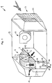
- a device designated in its entirety by 1 for filtering suspended matter or similar solid particles from air has a rotatably mounted air filter 2 which is flowed through by an air stream in its upper partial area and with its lower partial area circulates in a liquid bath 4 with cleaning liquid.
- the dirt or solid particles filtered out of the air and adhering to the air filter 2 are rinsed off as they pass through the liquid bath 4 and released to the cleaning liquid.
- the service life of the air filter 2 can thereby be extended considerably, so that the device 1 enables practically maintenance-free operation over a longer period even when the air is heavily loaded with solid particles.
- the air filter 2 has the shape of a circular cylindrical disc and contains an open-pore or mixed-pore filter material 5 in its interior, which is held together by a circumferential, cylindrical metal ring 6.
- the metal ring 6 is supported on the flat sides of the air filter 2 with a plurality of radially inwardly extending holding spokes or similar holding parts 7 on the rotary bearing 8 of the air filter 2.
- the axis of the rotary bearing 8 lies on the longitudinal center axis 9 of the air filter 2.
- the lower half of the air filter 2 engages in a cuboid liquid trough 10 which contains the cleaning liquid.
- a blower 11 is also integrated, which generates an air flow that penetrates the upper half of the air filter 2.
- the device 1 is particularly easy to handle and can be used, for example, on a construction site Room air filters can be used without the need to connect an external blower or an external air displacer.
- the air filter 2 can be arranged on the inflow or - as here - on the outflow side of the fan.
- the rotationally driven air filter 2 can rotate in the water bath, for example, by means of air blades arranged on the circumference and acted upon by the air flow, but it is also possible for the air filter 2 to be connected to a drive motor for this purpose.
- the air filter 2, the liquid pan 10 and the blower 11 are arranged in a common device housing 12 with a rectangular cross section.
- the device housing 12 has at its one end end an air inlet opening 13 for the air drawn in by the blower 11 and has at the opposite end end an air outlet opening 14 for the air cleaned by the air filter 2.
- a coarse filter 15 is provided in the air inlet opening 13 to remove coarse dirt particles. The air supplied to the air filter 2 is thereby already pre-cleaned, which additionally improves the service life of the air filter 2.
- the coarse filter 15 is easily accessible on the outside of the Vorrichtugsgephinuses 12 and can be easily cleaned or renewed if necessary.
- the liquid trough 10 has a liquid inlet with a magnetic shut-off valve 16, which is coupled to a level sensor 17 for regulating the fill level of the cleaning liquid. If the liquid level of the cleaning liquid should drop after a longer operating time of the device 1, for example due to evaporation of the cleaning liquid, the magnetic shut-off valve 16 of the liquid inlet is automatically opened by the fill level sensor 17 until the liquid level has again reached the intended target level. This prevents the filter from running dry. It is particularly advantageous if water is used as the cleaning liquid.
- the solenoid valve 16 can then be connected directly to a water pipe with a water hose 18.
- the filling level sensor 17 and the magnetic shut-off valve 16 also facilitate the refilling of the liquid trough 10 if it has been emptied, for example, for transporting the device 1.
- the water hose 18 then only needs to be connected to a water pipe for filling the liquid trough 10, the level sensor 17 automatically switching off the water supply with the magnetic shut-off valve 16 when the desired liquid level is reached.
- the liquid trough 10 also has a liquid drain 31 with a magnetic shut-off valve 19 which is coupled to a timer 20 for the interval-controlled drainage of the cleaning liquid and for subsequent rinsing of the liquid trough 10.
- the timer 20 first opens the magnetic shut-off valve 19 so that the cleaning liquid contained in the liquid trough 10 can run off.
- the magnetic shut-off valve 19 is then initially kept open for a certain time, at the same time, controlled by the fill level sensor 17, the water inlet being opened in order to flush away any filter sludge residues contained in the liquid pan 10. Then the magnetic shut-off valve 19 of the water drain is closed so that the liquid pan 10 can be filled with fresh water.
- the liquid trough 10 is followed by a collecting trough 21 on the air outlet side of the air filter 2.
- the upper edge of the drip pan 21 is arranged higher than that of the liquid pan 10, so that the drip pan 21 in the from Air filter 2 emerging air flow protrudes. Any cleaning liquid entrained by the air stream can thereby be collected in the collecting trough 21 and, for example, can be discharged in a controlled manner via an outlet provided in the collecting trough 21. Escaping cleaning liquid at the air outlet opening 14 of the device 1 is avoided.
- FIG. 2 shows how the device according to the invention can be used to dry a glass wool insulation layer located under a screed 23, which has become moist after the entry of water.
- a plurality of air suction hoses 24 are connected to the filter device 1, each of which is connected to an air suction channel 25, a slot nozzle connector 26 or a screw-in connector 27.
- the filter device 1 has a plurality of connection couplings 28 on the air inlet side, with which the air extraction hoses 24 can be connected to the filter device 1 in a simple manner.
- air can be sucked out of the dampened insulation layer at several points at the same time, so that it can be dried effectively.
- the moist air stored in the insulation layer can be extracted at an expansion joint 30, for example with an air extraction duct 25 or with slot nozzle connector 26 after removal of the joint sealing tape 29.
- the use of a screw-in socket 27 has proven to be particularly advantageous and can be inserted practically anywhere in the screed 23 after a corresponding opening, for example a hole, has been made.
- the moist air extracted from the glass wool insulation layer becomes in the device 1 directly supplied to the air filter 2, which filters out the glass or mineral fibers contained in the suction air, so that a release of mineral fibers which are hazardous to health is largely avoided. Since the air filter 2 circulating in the cleaning liquid is continuously regenerated, the device 1 enables effective filtering of the suction air even after a long period of operation. It may be expedient if the device 1 has a feed device for feeding a disinfectant, a fungicide or the like. Additive into the cleaning liquid.
- This feed device which is not shown here, can preferably be designed as an injector which is connected to an additive supply and which has at least one injection nozzle which is interposed in the liquid inlet or the inlet line.
- the liquid flow in the liquid inlet can also entrain the additive from the injector nozzle without the need for a pump or the like.
- additives can be introduced into the liquid trough 10 and the cleaning liquid contained therein, which counteract, for example, a fungal attack on the air filter.
Landscapes
- Chemical & Material Sciences (AREA)
- Engineering & Computer Science (AREA)
- Chemical Kinetics & Catalysis (AREA)
- Combustion & Propulsion (AREA)
- Mechanical Engineering (AREA)
- General Engineering & Computer Science (AREA)
- Ventilation (AREA)
Applications Claiming Priority (2)
| Application Number | Priority Date | Filing Date | Title |
|---|---|---|---|
| DE4417443 | 1994-05-19 | ||
| DE4417443A DE4417443A1 (de) | 1994-05-19 | 1994-05-19 | Vorrichtung zum Filtern von Schwebstoffen |
Publications (1)
| Publication Number | Publication Date |
|---|---|
| EP0683360A1 true EP0683360A1 (fr) | 1995-11-22 |
Family
ID=6518407
Family Applications (1)
| Application Number | Title | Priority Date | Filing Date |
|---|---|---|---|
| EP95107443A Withdrawn EP0683360A1 (fr) | 1994-05-19 | 1995-05-17 | Dispositif pour la filtration de matières en suspension |
Country Status (2)
| Country | Link |
|---|---|
| EP (1) | EP0683360A1 (fr) |
| DE (1) | DE4417443A1 (fr) |
Cited By (6)
| Publication number | Priority date | Publication date | Assignee | Title |
|---|---|---|---|---|
| WO1999047867A1 (fr) * | 1998-03-16 | 1999-09-23 | Geisert Guenter | Appareil d'humidification et de lavage de l'air |
| WO2005047777A1 (fr) * | 2003-11-13 | 2005-05-26 | Mjaatvedt Tore | Entree d'air dans une installation de ventilation |
| WO2010017572A1 (fr) * | 2008-08-12 | 2010-02-18 | Emanuel Migitsch | Dispositif de conditionnement d'air |
| CN107158860A (zh) * | 2017-05-08 | 2017-09-15 | 陈麒如 | 车载空气质量监控环流场异型风道除霾装置及其制造方法 |
| CN111219807A (zh) * | 2018-11-26 | 2020-06-02 | Cs E&L株式会社 | 多功能空气净化器以及包含其的空调系统 |
| CN111437674A (zh) * | 2020-05-25 | 2020-07-24 | 常州亚瑞过滤设备有限公司 | 一种平板玻璃纤维过滤网 |
Families Citing this family (2)
| Publication number | Priority date | Publication date | Assignee | Title |
|---|---|---|---|---|
| DE102004050401A1 (de) * | 2004-10-15 | 2006-04-20 | Edgar Emele Kunststofftechnik Präzisionsformen GmbH & Co. KG | Luftwäschegerät zur Luftreinigung und/oder Luftbefeuchtung |
| DE102015202398A1 (de) * | 2015-02-11 | 2015-12-17 | Voith Patent Gmbh | Filtervorrichtung |
Citations (7)
| Publication number | Priority date | Publication date | Assignee | Title |
|---|---|---|---|---|
| CH256505A (fr) * | 1945-11-30 | 1948-08-31 | Morel Stanislas | Filtre. |
| DE825083C (de) * | 1950-06-24 | 1951-12-17 | Friedrich Ibershoff | Vorrichtung zum Entfernen von in Luft, Gasen oder Daempfen befindlichen Schwebeteilchn |
| US3837148A (en) * | 1972-02-23 | 1974-09-24 | Texaco Inc | Apparatus for filtering flue gas |
| EP0093426A2 (fr) * | 1982-04-30 | 1983-11-09 | LOCTITE Deutschland GmbH | Procédé et dispositif pour épurer l'air de vapeurs de cyanacrylate |
| DE8502815U1 (de) * | 1985-02-02 | 1985-06-05 | Düpro AG, Romanshorn | Kleinvolumiges transportables Gerät zur Behandlung von Raumluft |
| US4731224A (en) * | 1984-12-14 | 1988-03-15 | Hitachi Elevator Engineering And Service Co., Ltd. | Deodorizer |
| EP0558919A1 (fr) * | 1992-01-31 | 1993-09-08 | Adam Jakob | Procédé et dispositif pour nettoyer un filtre |
Family Cites Families (1)
| Publication number | Priority date | Publication date | Assignee | Title |
|---|---|---|---|---|
| DE3414652A1 (de) * | 1984-04-18 | 1985-12-19 | Kurt 7712 Blumberg Geier-Henninger | Vorrichtung und verfahren zur reinigung von verschmutzter abluft |
-
1994
- 1994-05-19 DE DE4417443A patent/DE4417443A1/de not_active Ceased
-
1995
- 1995-05-17 EP EP95107443A patent/EP0683360A1/fr not_active Withdrawn
Patent Citations (7)
| Publication number | Priority date | Publication date | Assignee | Title |
|---|---|---|---|---|
| CH256505A (fr) * | 1945-11-30 | 1948-08-31 | Morel Stanislas | Filtre. |
| DE825083C (de) * | 1950-06-24 | 1951-12-17 | Friedrich Ibershoff | Vorrichtung zum Entfernen von in Luft, Gasen oder Daempfen befindlichen Schwebeteilchn |
| US3837148A (en) * | 1972-02-23 | 1974-09-24 | Texaco Inc | Apparatus for filtering flue gas |
| EP0093426A2 (fr) * | 1982-04-30 | 1983-11-09 | LOCTITE Deutschland GmbH | Procédé et dispositif pour épurer l'air de vapeurs de cyanacrylate |
| US4731224A (en) * | 1984-12-14 | 1988-03-15 | Hitachi Elevator Engineering And Service Co., Ltd. | Deodorizer |
| DE8502815U1 (de) * | 1985-02-02 | 1985-06-05 | Düpro AG, Romanshorn | Kleinvolumiges transportables Gerät zur Behandlung von Raumluft |
| EP0558919A1 (fr) * | 1992-01-31 | 1993-09-08 | Adam Jakob | Procédé et dispositif pour nettoyer un filtre |
Cited By (8)
| Publication number | Priority date | Publication date | Assignee | Title |
|---|---|---|---|---|
| WO1999047867A1 (fr) * | 1998-03-16 | 1999-09-23 | Geisert Guenter | Appareil d'humidification et de lavage de l'air |
| WO2005047777A1 (fr) * | 2003-11-13 | 2005-05-26 | Mjaatvedt Tore | Entree d'air dans une installation de ventilation |
| WO2010017572A1 (fr) * | 2008-08-12 | 2010-02-18 | Emanuel Migitsch | Dispositif de conditionnement d'air |
| CN107158860A (zh) * | 2017-05-08 | 2017-09-15 | 陈麒如 | 车载空气质量监控环流场异型风道除霾装置及其制造方法 |
| CN107158860B (zh) * | 2017-05-08 | 2018-03-06 | 陈麒如 | 车载空气质量监控环流场异型风道除霾装置及其制造方法 |
| CN111219807A (zh) * | 2018-11-26 | 2020-06-02 | Cs E&L株式会社 | 多功能空气净化器以及包含其的空调系统 |
| CN111219807B (zh) * | 2018-11-26 | 2021-05-28 | Cs E&L株式会社 | 多功能空气净化器以及包含其的空调系统 |
| CN111437674A (zh) * | 2020-05-25 | 2020-07-24 | 常州亚瑞过滤设备有限公司 | 一种平板玻璃纤维过滤网 |
Also Published As
| Publication number | Publication date |
|---|---|
| DE4417443A1 (de) | 1995-11-23 |
Similar Documents
| Publication | Publication Date | Title |
|---|---|---|
| DE19853190B4 (de) | Rotationswäscher mit schrägstehendem Demister | |
| DE202006020762U1 (de) | Anlage zum Lackieren von Gegenständen | |
| DE19651693C2 (de) | Automatische Scheibenreinigungsanlage | |
| EP2422010B1 (fr) | Sèche-linge domestique et procédé de filtrage | |
| EP3092928B1 (fr) | Appareil de sechage de couches isolantes pour planchers selon un procede a depression | |
| DE2640219A1 (de) | Kabine fuer eine elektrostatische pulver-beschichtungsanlage | |
| EP3737488A1 (fr) | Séparateur aérosol à plusieurs étages, module d'étages de préséparateur, procédé d'ajout et de fonctionnement | |
| DE4417443A1 (de) | Vorrichtung zum Filtern von Schwebstoffen | |
| DE1571759A1 (de) | Gasskrubber | |
| DE2537220C2 (de) | Vorrichtung zum Waschen von Gasen, vornehmlich zum Reinigen, Befeuchten und Kühlen von Luft | |
| DE9408210U1 (de) | Vorrichtung zum Filtern von Schwebstoffen | |
| DE4102167A1 (de) | Verfahren zur biologischen behandlung von abgasen und einrichtung zur ausfuehrung des verfahrens | |
| DE3408474A1 (de) | Farbspritzstand mit kontinuierlicher lackschlammabscheidung | |
| EP0247216B1 (fr) | Installation pour sécher des couches isolantes mouillées telles que des couches d'isolation acoustique, d'isolation thermique ou similaires | |
| DE3643299C1 (en) | Apparatus for dehumidifying the interior exhaust air or exhaust gases and/or for condensing the vapour and waste steam from bakeries or the like | |
| DE3201946C2 (de) | Vorrichtung zum Absaugen von Farbnebeln aus Farbspritzräumen | |
| CH622881A5 (en) | Heat and moisture exchanger | |
| DE102006043427B4 (de) | Vorrichtung und Verfahren zum Reinigen und Befeuchten von Luft | |
| AT405614B (de) | Verfahren und vorrichtung zum aufbereiten von kondensat | |
| CH682807A5 (de) | Industriefilter mit Abreinigungsvorrichtung. | |
| DE102019208553B4 (de) | Dunstabzugsvorrichtung mit Filtereinheit und Kombinationsgerät mit Dunstabzugsvorrichtung | |
| EP1445011A1 (fr) | Ventilateur purificateur d' air | |
| DE20302152U1 (de) | Luftreinigungsgebläse | |
| DE4422042A1 (de) | Abluftfilteranlage für Laser-Bearbeitungsanlagen | |
| DE2358346A1 (de) | Luftreinigungsgeraet |
Legal Events
| Date | Code | Title | Description |
|---|---|---|---|
| PUAI | Public reference made under article 153(3) epc to a published international application that has entered the european phase |
Free format text: ORIGINAL CODE: 0009012 |
|
| AK | Designated contracting states |
Kind code of ref document: A1 Designated state(s): AT BE CH DE FR LI |
|
| 17P | Request for examination filed |
Effective date: 19951130 |
|
| 17Q | First examination report despatched |
Effective date: 19970626 |
|
| STAA | Information on the status of an ep patent application or granted ep patent |
Free format text: STATUS: THE APPLICATION IS DEEMED TO BE WITHDRAWN |
|
| 18D | Application deemed to be withdrawn |
Effective date: 19980723 |