EP0683589A2 - Méthode et appareil pour dévier une connection téléphonique - Google Patents
Méthode et appareil pour dévier une connection téléphonique Download PDFInfo
- Publication number
- EP0683589A2 EP0683589A2 EP95106351A EP95106351A EP0683589A2 EP 0683589 A2 EP0683589 A2 EP 0683589A2 EP 95106351 A EP95106351 A EP 95106351A EP 95106351 A EP95106351 A EP 95106351A EP 0683589 A2 EP0683589 A2 EP 0683589A2
- Authority
- EP
- European Patent Office
- Prior art keywords
- subscriber
- connection
- unit
- station
- mobile station
- Prior art date
- Legal status (The legal status is an assumption and is not a legal conclusion. Google has not performed a legal analysis and makes no representation as to the accuracy of the status listed.)
- Ceased
Links
Images

Classifications
-
- H—ELECTRICITY
- H04—ELECTRIC COMMUNICATION TECHNIQUE
- H04M—TELEPHONIC COMMUNICATION
- H04M1/00—Substation equipment, e.g. for use by subscribers
- H04M1/006—Call diverting means
-
- H—ELECTRICITY
- H04—ELECTRIC COMMUNICATION TECHNIQUE
- H04M—TELEPHONIC COMMUNICATION
- H04M3/00—Automatic or semi-automatic exchanges
- H04M3/42—Systems providing special services or facilities to subscribers
- H04M3/54—Arrangements for diverting calls for one subscriber to another predetermined subscriber
-
- H—ELECTRICITY
- H04—ELECTRIC COMMUNICATION TECHNIQUE
- H04M—TELEPHONIC COMMUNICATION
- H04M7/00—Arrangements for interconnection between switching centres
Definitions
- the invention relates to a method and an arrangement for rerouting a telephone connection.
- the invention is particularly suitable for the diversion of a call arriving via the wired telephone network to a subscriber station of a mobile radio network.
- the reverse route namely to forward a call arriving at a subscriber station of the wired telephone network to a mobile station.
- One of the reasons for this is that in this case the relatively high fees for participating in the mobile radio system could be incurred by the calling subscriber. These charges are unexpectedly high, for example, if the calling subscriber intends to make a local call and to the called party Participant of this local call is then redirected to the mobile radio system.
- the invention is based on the object of specifying a method and an arrangement for rerouting telephone connections which can be implemented without intervention in the telephone network and in the mobile radio system and which, when used, result in no additional costs for the calling subscriber.
- the method and the arrangement according to the invention have the advantage that they can be easily installed by a subscriber.
- the arrangement can be plugged into conventional outlets for subscriber stations known, for example, under the name TAE, and it requires relatively little effort, so that it can be produced inexpensively.
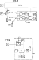
- a first subscriber is connected to a wired one Telephone network (Public Switched Telephone Network) PSTN connected subscriber station T1 wants to transmit information to a subscriber T2 also connected to the telephone network PSTN of a second subscriber.
- the information can be, for example, a conversation, data or a facsimile.
- the call from the subscriber station T1 arrives in a known manner via the telephone network PSTN and via the telephone line F1 to the connection unit A1 of the second subscriber.
- This connection unit A1 is designed, for example, like the known TAE socket.
- the subscriber station T2 is normally connected directly to the connection unit A1. In the present case, however, it is connected via a diversion unit U1.
- the diverting unit U1 contains a switch which connects the telephone line F1 either to the subscriber station T2 or to a control unit provided in the diverting unit U1. If the subscriber can be reached at the subscriber station T2, this is connected to the telephone line F1 via the changeover switch and the connection unit A1. However, if the subscriber is on the move and can be reached via his mobile station MS2, the call arrives at the control unit in the diversion unit U1. This automatically establishes a connection to the cellular network (Public Land Mobile Network) PLMN and reaches the mobile station MS2 via this cellular network PLMN.
- Public Land Mobile Network Public Land Mobile Network
- the mobile radio system is designed, for example, on the basis of an electronic switching system in accordance with the well-known digital cellular pan-European mobile radio system GSM (Global System for Mobile Communication). It contains a switching system which is formed from a plurality of switching centers MSC connected to the telephone network PSTN. A radio system is connected to each switching center MSC and is formed from a plurality of base station controls B and base radio stations BTS connected to them, of which only the base station controls B1 and B2 or the base radio stations BTS 1 and BTS 2 are shown in FIG. 1.
- GSM Global System for Mobile Communication
- the data from mobile stations registered there are stored in the home file HLR, and the visitor file VLR contains the information about those mobile stations that are currently in the respective visitor file area.
- a mobile radio system is described, for example, in a brochure "D900 Mobile Communication System” SYD from Siemens AG.
- the diversion unit U1 contains the essential components of a mobile station, such as, for example, a transmitter / receiver unit connected to an antenna and the units required for billing, since the diversion unit U1 acts like a mobile station with respect to the PLMN mobile radio system.
- the diversion unit U1 In the event of a call arriving from the subscriber station T1 via the trunk line F1, the diversion unit U1 automatically establishes a connection to the mobile radio network PLMN at the subscriber station T2, either immediately or, for example, after the third ring.
- the redirection unit U1 When the redirection unit U1 is switched on, it has logged into the mobile radio system like a mobile station, and its data are stored in the home location file HLR.
- an automatic dialing device in the control unit ST establishes a connection to the switching center MSC via the base radio station BTS1 and the base station controller B1. This determines where the MS2 mobile station is currently located.
- the switching center MSC If it is in the radio area for which the switching center MSC is responsible, it forwards the call via the base station controller B2 and the base radio station BTS2 to the mobile station MS2 and establishes the telephone connection. If the mobile station MS2 is in the radio range of another switching center, the switching center MSC establishes a connection to this switching center and via the telephone network PSTN via a corresponding base station controller and a corresponding base radio station to the mobile station MS2.
- a call of the first subscriber is diverted in a corresponding manner if the call does not originate from the subscriber station T1 but from a mobile station MS1 assigned to the first subscriber and reaches the subscriber station T2 via the telephone network PSTN.
- a text stored in the diversion unit U1 can be sent to the subscriber station T1, which informs the subscriber there that the desired subscriber is being called via the mobile radio system or pause music is being sent.
- the switch U is connected to the telephone line F1, which connects the telephone line F1 either to the subscriber station T2 or to the control unit ST.
- the switch U is controlled by a call detection unit RE, which, similar to an answering machine, brings the switch U into the position shown in dashed lines, for example after the third ring, and then connects the trunk line F1 to the control unit ST.
- the control unit ST contains an automatic selection device which is designed in a known manner. In the present case, it establishes a connection to the corresponding base radio station BTS1 via a transceiver SE and an antenna AN.
- the call number of the mobile station MS2 is stored in a memory S1 and can either be permanently installed or, in the event of a possible diversion to different mobile stations, entered using a keyboard T.
- the keyboard T can also be used to enter whether the connection to the mobile station MS2 is over immediately after the arrival of a call the telephone line F1 is to take place or only after a certain number of ringing signals.
- the diversion unit U1 is a mobile station, and thus the billing is also carried out, as with a conventional mobile station, at the expense of the owner of the diversion unit U1 and not at the expense of the subscriber calling via the subscriber station T1.
- the time delay that may exist when establishing a connection and the corresponding text that may be transmitted it is irrelevant for the calling subscriber whether the call arrives at the subscriber station T2 or the mobile station MS2.
- the called subscriber it is advantageous that he can always be reached under a single telephone number, which is particularly important in business dealings.
- the call arriving from the subscriber station T1 or MS1 is diverted to the mobile station MS2 using the telephone network PSTN.
- a connection unit A2 connected to a second telephone line F2 is additionally provided for subscriber T2. This is also designed, for example, like the well-known TAE box. If a call from the subscriber station T1 reaches the diversion unit U2 via the telephone line F1 and the subscriber does not accept the call at the subscriber station T2, a connection is established in the diversion unit U2 via the telephone line F2 to the mobile station MS2. The connection is established as with a normal call from a subscriber connected to the wired telephone network PSTN to a mobile station.
- a connection to the corresponding switching center MSC of the cellular network PLMN is established, and the call is forwarded to the mobile station MS2 in the manner described above. If the called subscriber can be reached via the mobile station MS2, the connection between the two telephone lines F1 and F2 is established in the diversion unit U2, so that the subscriber to the mobile station MS2 can accept the call from the subscriber station T1 via the diversion unit U2.
- the diverting unit U2 shown in FIG. 3 differs from the diverting unit U1 shown in FIG. 2 essentially in that the units required for the connection to the cellular network PLMN are replaced by the units required for a connection to the telephone network PSTN.
- the diverting unit U2 is like a conventional subscriber station with an automatic dialing device.
- text or pause music stored in the memory S2 can be transmitted to the subscriber station T1 during the establishment of the connection to the mobile station MS2.
- the call number of the desired mobile station MS2 can also be entered into the memory S1 using the keyboard T.
- this diversion unit U2 can also be used to enter any number of a subscriber connected to the wired telephone network PSTN.
- the diversion units U1 and U2 can also be parts of private branch exchanges to which further subscriber stations are connected directly.
- the mobile station MS2 can then be called by means of a further subscriber station T3 connected to the diversion unit U2.
Landscapes
- Engineering & Computer Science (AREA)
- Signal Processing (AREA)
- Mobile Radio Communication Systems (AREA)
Applications Claiming Priority (2)
| Application Number | Priority Date | Filing Date | Title |
|---|---|---|---|
| DE4416715 | 1994-05-11 | ||
| DE4416715 | 1994-05-11 |
Publications (2)
| Publication Number | Publication Date |
|---|---|
| EP0683589A2 true EP0683589A2 (fr) | 1995-11-22 |
| EP0683589A3 EP0683589A3 (fr) | 1999-08-25 |
Family
ID=6517925
Family Applications (1)
| Application Number | Title | Priority Date | Filing Date |
|---|---|---|---|
| EP95106351A Ceased EP0683589A3 (fr) | 1994-05-11 | 1995-04-27 | Méthode et appareil pour dévier une connection téléphonique |
Country Status (2)
| Country | Link |
|---|---|
| EP (1) | EP0683589A3 (fr) |
| FI (1) | FI952291L (fr) |
Cited By (3)
| Publication number | Priority date | Publication date | Assignee | Title |
|---|---|---|---|---|
| DE19631327A1 (de) * | 1996-08-02 | 1998-02-05 | Deutsche Telephonwerk Kabel | Verfahren zur Rufumleitung |
| WO1998021900A1 (fr) * | 1996-11-08 | 1998-05-22 | Telefonaktiebolaget Lm Ericsson (Publ) | Procede et dispositif de transfert d'appel dans un reseau intelligent |
| EP0841798A3 (fr) * | 1996-11-07 | 2002-08-28 | Nokia Corporation | Renvoi d'appel |
Family Cites Families (5)
| Publication number | Priority date | Publication date | Assignee | Title |
|---|---|---|---|---|
| FR2533386A1 (fr) * | 1982-09-21 | 1984-03-23 | Sedeca | Procede de gestion des appels dans un reseau de communications telephoniques |
| JPS61171297A (ja) * | 1985-01-25 | 1986-08-01 | Fujitsu Ltd | 外線転送方式 |
| US5222123A (en) * | 1990-01-08 | 1993-06-22 | Motorola, Inc. | Registration and automatic call redirecting for cordless telephone systems |
| US5329578A (en) * | 1992-05-26 | 1994-07-12 | Northern Telecom Limited | Personal communication service with mobility manager |
| JPH06188995A (ja) * | 1992-08-31 | 1994-07-08 | American Teleph & Telegr Co <Att> | 呼経路指定伝送装置およびその方法 |
-
1995
- 1995-04-27 EP EP95106351A patent/EP0683589A3/fr not_active Ceased
- 1995-05-11 FI FI952291A patent/FI952291L/fi not_active Application Discontinuation
Cited By (4)
| Publication number | Priority date | Publication date | Assignee | Title |
|---|---|---|---|---|
| DE19631327A1 (de) * | 1996-08-02 | 1998-02-05 | Deutsche Telephonwerk Kabel | Verfahren zur Rufumleitung |
| DE19631327B4 (de) * | 1996-08-02 | 2005-04-14 | Detewe Deutsche Telephonwerke Aktiengesellschaft & Co. Kg | Verfahren zur Rufumleitung |
| EP0841798A3 (fr) * | 1996-11-07 | 2002-08-28 | Nokia Corporation | Renvoi d'appel |
| WO1998021900A1 (fr) * | 1996-11-08 | 1998-05-22 | Telefonaktiebolaget Lm Ericsson (Publ) | Procede et dispositif de transfert d'appel dans un reseau intelligent |
Also Published As
| Publication number | Publication date |
|---|---|
| EP0683589A3 (fr) | 1999-08-25 |
| FI952291A7 (fi) | 1995-11-12 |
| FI952291A0 (fi) | 1995-05-11 |
| FI952291L (fi) | 1995-11-12 |
Similar Documents
| Publication | Publication Date | Title |
|---|---|---|
| DE69413149T2 (de) | Verfahren zur telefonverbindungsherstellung in einem telefonsystem | |
| DE69735770T2 (de) | Bereitstellung einer ortsbasierten anrufumleitung in einem mobilen telekommunikationsnetzwerk | |
| DE69131049T2 (de) | Struktur eines mobiltelefonnetzes | |
| DE69214772T2 (de) | Verfahren zur durchschaltung eines ankommenden rufes für ein mobil-telefon in einem zellularen mobil-telefonnetz | |
| DE69124643T2 (de) | Mobiles Kommunikationssystem | |
| DE4105884C2 (fr) | ||
| EP0893933B1 (fr) | Procédé de contrôle d'acheminement d'appels | |
| EP0518344A2 (fr) | Etablissement d'une connexion entre terminaux mobiles d'abonnés de réseaux groupés | |
| EP0920147A2 (fr) | Procédé, système et réseau d'établissement d'une connection téléphonique vers des personnes placées dans des lieux fermés, comme des moyens de transport par exemple | |
| DE69319035T2 (de) | Architektur für drahtloses zellular Telekommunikationssystem | |
| DE19815430B4 (de) | Verfahren zum Verbindungsaufbau von einem Mobilfunknetz zu einer Zielrufnummer eines privaten Kommunikationsnetzes | |
| EP0676905B1 (fr) | Procédé pour établir une connexion avec un abonné par un premier réseau, ainsi qu'un processeur de service, un dispositif de commutation et un terminal | |
| DE19745350C1 (de) | Mobilfunktelefon für Multi-Mode-Betrieb und Verwendung einer Relaisstation für derartige Mobilfunktelefone | |
| DE69934498T2 (de) | Heimzonen-nebenstellentelefondienst | |
| EP0456128A2 (fr) | Méthode pour détourner et renvoyer les appels dans des centraux téléphoniques | |
| DE3438293C2 (fr) | ||
| DE2848931C2 (de) | Schaltungsanordnung für Teilnehmerstationen | |
| EP0683589A2 (fr) | Méthode et appareil pour dévier une connection téléphonique | |
| DE69823916T2 (de) | Verfahren und System zum Zugriff auf ein Telekommunikationsnetz | |
| EP2237581B1 (fr) | Procédé et agencement de transmission d'une information prédéfinie pour connexions de radios mobiles | |
| AT406215B (de) | Telefonanlage | |
| EP0760588B1 (fr) | Méthode et dispositif d'établissement de liaisons de télécommunication | |
| DE19628426C2 (de) | Verfahren zur Verknüpfung von Kommunikationsnetzen | |
| DE4411119C1 (de) | Digitales, in Funkzellen aufgebautes Mobilfunksystem | |
| EP1235442B1 (fr) | Méthode de gestion d'un réseau de télécommunication privé |
Legal Events
| Date | Code | Title | Description |
|---|---|---|---|
| PUAI | Public reference made under article 153(3) epc to a published international application that has entered the european phase |
Free format text: ORIGINAL CODE: 0009012 |
|
| AK | Designated contracting states |
Kind code of ref document: A2 Designated state(s): DE ES FR GB IT SE |
|
| PUAL | Search report despatched |
Free format text: ORIGINAL CODE: 0009013 |
|
| AK | Designated contracting states |
Kind code of ref document: A3 Designated state(s): DE ES FR GB IT SE |
|
| RIC1 | Information provided on ipc code assigned before grant |
Free format text: 6H 04M 3/54 A, 6H 04Q 7/22 B, 6H 04M 1/65 B, 6H 04Q 7/38 B |
|
| 17P | Request for examination filed |
Effective date: 20000224 |
|
| 17Q | First examination report despatched |
Effective date: 20001127 |
|
| GRAG | Despatch of communication of intention to grant |
Free format text: ORIGINAL CODE: EPIDOS AGRA |
|
| STAA | Information on the status of an ep patent application or granted ep patent |
Free format text: STATUS: THE APPLICATION HAS BEEN REFUSED |
|
| 18R | Application refused |
Effective date: 20020826 |