EP0683619A2 - Méthode et appareil pour la déviation d'un courant de cellules de communication sur une voie alternative - Google Patents
Méthode et appareil pour la déviation d'un courant de cellules de communication sur une voie alternative Download PDFInfo
- Publication number
- EP0683619A2 EP0683619A2 EP95106942A EP95106942A EP0683619A2 EP 0683619 A2 EP0683619 A2 EP 0683619A2 EP 95106942 A EP95106942 A EP 95106942A EP 95106942 A EP95106942 A EP 95106942A EP 0683619 A2 EP0683619 A2 EP 0683619A2
- Authority
- EP
- European Patent Office
- Prior art keywords
- message cell
- path
- cell stream
- message
- synchronization
- Prior art date
- Legal status (The legal status is an assumption and is not a legal conclusion. Google has not performed a legal analysis and makes no representation as to the accuracy of the status listed.)
- Ceased
Links
- 238000004891 communication Methods 0.000 title claims abstract description 21
- 238000000034 method Methods 0.000 title claims description 31
- 230000008878 coupling Effects 0.000 claims abstract description 75
- 238000010168 coupling process Methods 0.000 claims abstract description 75
- 238000005859 coupling reaction Methods 0.000 claims abstract description 75
- 238000011156 evaluation Methods 0.000 claims description 23
- 230000005540 biological transmission Effects 0.000 claims description 13
- 230000003111 delayed effect Effects 0.000 claims description 7
- 230000001360 synchronised effect Effects 0.000 claims description 7
- 230000004044 response Effects 0.000 claims description 6
- 239000000872 buffer Substances 0.000 description 21
- 230000015654 memory Effects 0.000 description 17
- 230000006870 function Effects 0.000 description 4
- 230000008901 benefit Effects 0.000 description 3
- 230000008569 process Effects 0.000 description 3
- 230000008859 change Effects 0.000 description 2
- 238000012546 transfer Methods 0.000 description 2
- 230000004913 activation Effects 0.000 description 1
- 230000006727 cell loss Effects 0.000 description 1
- 238000006243 chemical reaction Methods 0.000 description 1
- 238000013461 design Methods 0.000 description 1
- 238000010586 diagram Methods 0.000 description 1
- 238000005516 engineering process Methods 0.000 description 1
- 230000000977 initiatory effect Effects 0.000 description 1
- 238000012423 maintenance Methods 0.000 description 1
Images


Classifications
-
- H—ELECTRICITY
- H04—ELECTRIC COMMUNICATION TECHNIQUE
- H04L—TRANSMISSION OF DIGITAL INFORMATION, e.g. TELEGRAPHIC COMMUNICATION
- H04L45/00—Routing or path finding of packets in data switching networks
- H04L45/02—Topology update or discovery
- H04L45/10—Routing in connection-oriented networks, e.g. X.25 or ATM
-
- H—ELECTRICITY
- H04—ELECTRIC COMMUNICATION TECHNIQUE
- H04B—TRANSMISSION
- H04B1/00—Details of transmission systems, not covered by a single one of groups H04B3/00 - H04B13/00; Details of transmission systems not characterised by the medium used for transmission
- H04B1/74—Details of transmission systems, not covered by a single one of groups H04B3/00 - H04B13/00; Details of transmission systems not characterised by the medium used for transmission for increasing reliability, e.g. using redundant or spare channels or apparatus
-
- H—ELECTRICITY
- H04—ELECTRIC COMMUNICATION TECHNIQUE
- H04J—MULTIPLEX COMMUNICATION
- H04J3/00—Time-division multiplex systems
- H04J3/02—Details
- H04J3/06—Synchronising arrangements
- H04J3/062—Synchronisation of signals having the same nominal but fluctuating bit rates, e.g. using buffers
- H04J3/0632—Synchronisation of packets and cells, e.g. transmission of voice via a packet network, circuit emulation service [CES]
-
- H—ELECTRICITY
- H04—ELECTRIC COMMUNICATION TECHNIQUE
- H04L—TRANSMISSION OF DIGITAL INFORMATION, e.g. TELEGRAPHIC COMMUNICATION
- H04L1/00—Arrangements for detecting or preventing errors in the information received
- H04L1/22—Arrangements for detecting or preventing errors in the information received using redundant apparatus to increase reliability
-
- H—ELECTRICITY
- H04—ELECTRIC COMMUNICATION TECHNIQUE
- H04L—TRANSMISSION OF DIGITAL INFORMATION, e.g. TELEGRAPHIC COMMUNICATION
- H04L45/00—Routing or path finding of packets in data switching networks
- H04L45/22—Alternate routing
-
- H—ELECTRICITY
- H04—ELECTRIC COMMUNICATION TECHNIQUE
- H04Q—SELECTING
- H04Q11/00—Selecting arrangements for multiplex systems
- H04Q11/04—Selecting arrangements for multiplex systems for time-division multiplexing
- H04Q11/0428—Integrated services digital network, i.e. systems for transmission of different types of digitised signals, e.g. speech, data, telecentral, television signals
- H04Q11/0478—Provisions for broadband connections
-
- H—ELECTRICITY
- H04—ELECTRIC COMMUNICATION TECHNIQUE
- H04L—TRANSMISSION OF DIGITAL INFORMATION, e.g. TELEGRAPHIC COMMUNICATION
- H04L12/00—Data switching networks
- H04L12/54—Store-and-forward switching systems
- H04L12/56—Packet switching systems
- H04L12/5601—Transfer mode dependent, e.g. ATM
- H04L2012/5625—Operations, administration and maintenance [OAM]
- H04L2012/5627—Fault tolerance and recovery
-
- H—ELECTRICITY
- H04—ELECTRIC COMMUNICATION TECHNIQUE
- H04L—TRANSMISSION OF DIGITAL INFORMATION, e.g. TELEGRAPHIC COMMUNICATION
- H04L12/00—Data switching networks
- H04L12/54—Store-and-forward switching systems
- H04L12/56—Packet switching systems
- H04L12/5601—Transfer mode dependent, e.g. ATM
- H04L2012/5672—Multiplexing, e.g. coding, scrambling
- H04L2012/5674—Synchronisation, timing recovery or alignment
Definitions
- the message cells transmitted via the active path and the substitute path are forwarded to the output of the coupling device located at the end of the path pair that is possible for the path pair.
- the number of message cells arriving via the active path and the replacement path is continuously at the relevant output recorded separately. If a number of message cells arriving via the replacement path is present, which is a fixed value above the number of message cells arriving via the active path, the message cells arriving via the replacement path are forwarded, while the message cells arriving via the active path are discarded.
- control cells are finally inserted periodically into the two message cell streams.
- the occurrence of the control cells in the lagging message cell stream only triggers the forwarding of the message cells without switching the selector.
- further details regarding the control cells used and their evaluation in the line-specific buffers cannot be found in the document mentioned.
- the object is achieved in a method according to the preamble of claims 1 and 2 by the method features specified in these claims.
- the invention has the advantage that a path-specific or connection-specific rerouting of a message cell stream from an active path to an alternative path can be carried out with a relatively low expenditure on control technology.
- the transmission of continuously changing sequence numbers in defined control cells and the evaluation of these sequence numbers ensure trouble-free rerouting.
- Such a virtual path can contain, for example, up to 65536 virtual connections and can also have a high total bit rate of, for example, up to 2.4 Gbyte / s, if necessary, such a virtual path must be switched over to an alternative path as quickly as possible, ie without cell loss, without duplication of cells, without falsification of information in the individual cells and in compliance with the cell order.
- an alternative path is defined within the ATM communication network for each path, hereinafter referred to as the active path.
- the respective active path and the associated replacement path are referred to below as the path pair and run over separate paths.
- message cells may only be forwarded via the active path AP to an interface device T3 which represents an output of the coupling device CCb.
- an interface device T3 which represents an output of the coupling device CCb.
- NST network control device
- the message cells arriving via this replacement path are forwarded to the interface device T3.
- the replacement path EP can either be determined based on the control mentioned in accordance with the network load and the required transmission capacity, or may already be defined with regard to the path, with the latter then only for control for the replacement path a transmission capacity corresponding to the transmission capacity of the active path is requested.
- the requested transmission capacity can be used for a low-priority message traffic up to a corresponding initiation.
- the switchover from the active path AP to the replacement path EP takes place with the aid of a synchronization device which is present in the interface device T3 and is at least temporarily assigned to the active path, the possible structure of which is shown in more detail in FIG. It is assumed that message cells arriving via the feeder path VPC are transmitted exclusively from the interface device R1 of the coupling device CCa via the active path AP to the interface device T3 of the coupling device CCb.
- the internal cell header provided in the coupling device CCb for the virtual path contains information for the transmission of message cells from the interface device R3 to the interface device T3.
- the respective internal cell header is in the interface device R1 or R3 and in the corresponding interface devices of the others Coupling devices of the communication network ATMN included in the virtual path are stored.
- the so-called conversion principle can also be used alternatively for the forwarding of message cells within the respective coupling device, according to which only the external cell header associated with the respective message cell is modified.
- a synchronization device which is present in the interface device T3 and is explained in more detail below is activated.
- a control signal in the form of at least one OAM cell indicating the activation of the synchronization device is then transmitted from this interface device T3 or the associated control device STb to the control device STa of the coupling device CCa.
- a virtual control channel set up between the two coupling devices CCb and CCa can be used for this purpose, which is set up, for example, in a path assigned to the active path AP, but running in the opposite direction.
- the message cell streams arriving via the active path AP and the replacement path EP are synchronized by compensating for the different delay times that occur on these paths. If a shorter delay time occurs on the active path than on the replacement path, the message cells transmitted via the active path are delayed in order to achieve synchronization with the message cells on the replacement path. On the other hand, if the message cells on the replacement path experience a smaller delay than the associated message cells on the active path, the message cells transmitted via the replacement path are delayed accordingly.
- the system then switches over to the replacement path, ie from this point in time only the message cells arriving via the replacement path are then forwarded via the interface device T3.
- the switchover thus completed is displayed, for example, to the control device associated with the switching device CCb by a corresponding OAM cell.
- the control device STa of the coupling device CCa becomes a control signal via the aforementioned control channel for example in the form of at least one OAM cell indicating the switchover to the replacement path, whereupon, under the control of the control device STa, the internal cell header previously stored in the interface device R1 is modified such that message cells are subsequently only forwarded via the replacement path EP.
- the aforementioned reversal signal (OAM cell or OAM cells) was supplied to the control device STb from the network control device NST.
- this OAM cell or these OAM cells can also be fed to the control device STa of the coupling device CCa.
- a defined OAM cell is first transmitted from the control device STa, for example via the active path AP, to the control device STb, on which the control processes explained above take place in the control device STb and subsequently in the control device STa.
- the synchronization device designated SY has on the input side a data switch DW which, from the coupling device CCb, first the message cell stream occurring via the active path AP and then additionally during the synchronization phase in multiplex operation the message cell stream occurring via the replacement path EP is fed.
- a specially marked OAM cell is inserted into the respective message cell stream, for example by the coupling device CCa.
- These OAM cells each have a sequence number that changes continuously from OAM cell to OAM cell.
- an OAM cell is inserted after every 256 message cells and the respective message cell stream is delayed, and the respective sequence number is coded by 8 bits.
- such an OAM cell can also replace an empty cell which is contained in the respective message cell stream and follows the specified number of message cells. If such an empty cell does not occur within a specified time, for example a time defined by 128 cells, an OAM cell is inserted into the message cell stream in a targeted manner, and this is done by delaying the message cell stream by 1 cell. With this procedure, however, the specified intervals for inserting OAM cells should be observed on average.
- the occurrence of the aforementioned reversal signal the occurrence of OAM cells is continuously monitored by the respective evaluation device A1 or A2 and the respective OAM cell is fed to the control device C.
- Subsequent message cells of the leading message cell stream are then temporarily stored under the control of the control device C in the respective buffer memory (P1 or P2) before forwarding, until a sequence number occurs in the lagging message cell stream which corresponds to the sequence number just determined for the leading message cell stream. If these sequence numbers are identical, ie if the two message cell streams are synchronized, the switching device S is then controlled by the control device C in such a way that only the message cells arriving via the replacement path are forwarded.
- a single active path can be switched to an assigned replacement path with the aid of the synchronization device SY shown in FIG. 3.
- Such a synchronization device can also be assigned to a plurality of virtual paths in multiplex mode if these are to be switched sequentially to an alternative path respectively assigned to them. If a simultaneous switching of virtual paths is required, a number of synchronization devices corresponding to the number of virtual paths to be switched simultaneously can be provided.
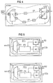
- FIGS. 4 and 5 show a further exemplary embodiment for the rerouting of a message cell stream from the active path AP to the substitute path EP.
- control processes in the coupling devices CCa and CCb which correspond to the control processes explained above, take place in response to a reversal signal emitted by the network control device NST (FIG. 1).
- NST network control device
- control device SC receives control signals (OAM cells) from the control device MC with sequence numbers received by them, in order to use them to control a corresponding, if necessary gradual, delay of message cells.
- control signals (OAM cells) are exchanged between the two control devices MC and SC in order to subsequently forward the message cell stream supplied to the interface device R2 to the interface device T3, specifically while suppressing the message cell stream supplied to the interface device R3. The required redirection of the message cell stream from the active path AP to the replacement path EP is then completed.
- synchronization devices SY1 and SY2 shown in FIG. 5 it should also be pointed out that further circuit elements consisting of a buffer memory, a downstream evaluation device and a control device can be connected to the respective data switch in order to simultaneously activate a plurality of virtual paths on assigned replacement paths to be able to switch.
- the respective buffer memory P3, P4
- P3, P4 can also be used as a common buffer memory for several virtual paths be designed so that the associated data switch can be dispensed with.
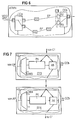
- FIGS. 6 and 7 show a third exemplary embodiment for redirecting a message cell stream from an active path to an alternative path.
- the synchronization and the switchover to the replacement path takes place after synchronization has taken place with the aid of synchronization devices present in the interface devices R2 and R3 and at least temporarily assigned to the active path with the replacement path.
- the synchronization device associated with the interface device R2 is designated SY3.
- the synchronization device associated with the interface device R3 bears the designation SY4.
- the synchronization device SY3 has a data switch DW3 which is used to receive a message cell stream and to which a buffer memory P5 is connected.
- the synchronization device SY4 contains a data switch DW4, a buffer memory P6 and an evaluation device A6 connected downstream of this.
- These circuit parts correspond to their function according to the circuit elements explained above, designated DW1, DW2, P3, P4, A3 and A4 in FIG.
- a difference to the synchronizing devices SY1 and SY2 shown in FIG. 5 is, however, that the synchronizing devices SY3 and SY4 shown in FIG. 7 have no individual control device.
- a central control device C1 is provided here according to FIG. 6, whose function and the connection to the respective buffer memory and to the respective evaluation device corresponds to the control device C previously explained with reference to FIG. That is, this control device C1, after the occurrence of a changeover signal mentioned above, delivers the OAM cells supplied by the two evaluation devices R2 Contained sequence numbers evaluated to delay the currently leading message cell stream based on these sequence numbers, if necessary, gradually again.
- the central control device C1 is connected to the synchronization devices SY3 and SY4 via a line system.
- a line system This can be designed, for example, as a ring line system or as a double bus line system with a forward and backward direction. In the latter case, the central control device C1 can be associated with the head stations present in such a bus line system.
- Any communication protocols can be used for communication with the evaluation devices A5 and A6 and for controlling the buffer memories P5 and P6. Examples include the DQDB protocol according to the IEEE standard 802.6 and the CRMAII protocol.
- synchronization devices SY3 and SY4 shown in FIG. 7 it should be pointed out that further circuit elements consisting of a buffer memory and a downstream evaluation device can be connected to the data switches DW3 and DW4 associated with these synchronization devices in order to simultaneously assign a plurality of virtual paths to assigned ones To be able to switch replacement paths.
- the respective buffer memory P5 or P6 can also be designed as a common buffer memory for a plurality of virtual paths, so that the associated data switch DW3 or DW4 can be dispensed with.
- a multiplicity of synchronizing devices can be connected to the line system (ring line system or double bus line system) which are associated with the input side interface devices of the coupling device CCb (FIG. 6). In this way, the diversion of a plurality of message cell streams from an active path to an alternative path can be controlled by the central control device C1.
- the above method for switching from virtual paths to replacement paths can also be modified in such a way that a supplied message cell stream is constantly transmitted by the coupling device CCa by duplication, both via an active path and via an assigned replacement path, and that resulting two message cell streams are fed to the previously described synchronization devices shown in FIGURES 3, 5 and 7.
- the synchronization described above is carried out continuously in order to switch to the remaining path in the event of a failure.
Landscapes
- Engineering & Computer Science (AREA)
- Computer Networks & Wireless Communication (AREA)
- Signal Processing (AREA)
- Multimedia (AREA)
- Computer Hardware Design (AREA)
- Data Exchanges In Wide-Area Networks (AREA)
Applications Claiming Priority (2)
| Application Number | Priority Date | Filing Date | Title |
|---|---|---|---|
| DE4416718 | 1994-05-11 | ||
| DE4416718A DE4416718C2 (de) | 1994-05-11 | 1994-05-11 | Schaltungsanordnung zum störungsfreien Umleiten eines Nachrichtenzellenstromes auf einen Ersatzweg |
Publications (2)
| Publication Number | Publication Date |
|---|---|
| EP0683619A2 true EP0683619A2 (fr) | 1995-11-22 |
| EP0683619A3 EP0683619A3 (fr) | 1998-06-24 |
Family
ID=6517927
Family Applications (1)
| Application Number | Title | Priority Date | Filing Date |
|---|---|---|---|
| EP95106942A Ceased EP0683619A3 (fr) | 1994-05-11 | 1995-05-08 | Méthode et appareil pour la déviation d'un courant de cellules de communication sur une voie alternative |
Country Status (5)
| Country | Link |
|---|---|
| US (1) | US5627822A (fr) |
| EP (1) | EP0683619A3 (fr) |
| JP (1) | JPH0851440A (fr) |
| CA (1) | CA2148997A1 (fr) |
| DE (1) | DE4416718C2 (fr) |
Cited By (1)
| Publication number | Priority date | Publication date | Assignee | Title |
|---|---|---|---|---|
| EP0788259A3 (fr) * | 1996-02-02 | 2001-02-14 | Nec Corporation | Système de routage |
Families Citing this family (36)
| Publication number | Priority date | Publication date | Assignee | Title |
|---|---|---|---|---|
| FR2737371A1 (fr) * | 1995-07-26 | 1997-01-31 | Trt Telecom Radio Electr | Securisation par doublement d'au moins certaines voies logiques dans un reseau de telecommunications |
| JPH0974412A (ja) * | 1995-09-04 | 1997-03-18 | Fujitsu Ltd | Atm交換網のapsシステム |
| JP3432664B2 (ja) * | 1996-02-14 | 2003-08-04 | 富士通株式会社 | 通信ノード及び障害復旧方法並びに通信ネットワーク |
| JP3473262B2 (ja) | 1996-04-05 | 2003-12-02 | 株式会社日立製作所 | パケット通信装置 |
| US5854899A (en) * | 1996-05-09 | 1998-12-29 | Bay Networks, Inc. | Method and apparatus for managing virtual circuits and routing packets in a network/subnetwork environment |
| EP0983667B1 (fr) * | 1997-05-22 | 2007-08-29 | Telcordia Technologies, Inc. | Systeme et procede pour compenser le temps de propagation dans un reseau dynamique de commutation de paquets |
| US6065062A (en) * | 1997-12-10 | 2000-05-16 | Cisco Systems, Inc. | Backup peer pool for a routed computer network |
| US6587441B1 (en) | 1999-01-22 | 2003-07-01 | Technology Alternatives, Inc. | Method and apparatus for transportation of data over a managed wireless network using unique communication protocol |
| US6665726B1 (en) * | 2000-01-06 | 2003-12-16 | Akamai Technologies, Inc. | Method and system for fault tolerant media streaming over the internet |
| US7028071B1 (en) | 2000-01-28 | 2006-04-11 | Bycast Inc. | Content distribution system for generating content streams to suit different users and facilitating e-commerce transactions using broadcast content metadata |
| US7463581B1 (en) | 2000-02-07 | 2008-12-09 | Cisco Technology, Inc. | Re-routing connections using redundant path connections and loopbacks |
| US7002908B1 (en) * | 2000-02-28 | 2006-02-21 | Telefonaktiebolaget Lm Ericsson (Publ) | Interconnection link redundancy in a modular switch node |
| US6725274B1 (en) * | 2000-03-29 | 2004-04-20 | Bycast Inc. | Fail-safe system for distributing streaming media having a dynamically reconfigurable hierarchy of ring or mesh topologies |
| US7099327B1 (en) * | 2000-10-12 | 2006-08-29 | Lucent Technologies Inc. | Data communications networks with high performance and reliability |
| DE10112814B4 (de) * | 2001-03-16 | 2004-07-08 | Siemens Ag | Verfahren zur Umverlegung einer operativen Verbindung auf eine alternative Verbindung in einem Kommunikationsnetz |
| US7031253B1 (en) | 2001-06-01 | 2006-04-18 | Cisco Technology, Inc. | Method and apparatus for computing a path through specified elements in a network |
| US6975588B1 (en) | 2001-06-01 | 2005-12-13 | Cisco Technology, Inc. | Method and apparatus for computing a path through a bidirectional line switched |
| US7051113B1 (en) | 2001-06-01 | 2006-05-23 | Cisco Technology, Inc. | Method and apparatus for computing a primary path while allowing for computing an alternate path by using a blocked list |
| US7082124B1 (en) | 2001-07-10 | 2006-07-25 | Cisco Technology, Inc. | Method and apparatus for computing primary and alternate paths in mixed protection domain networks |
| US7490165B1 (en) | 2001-07-18 | 2009-02-10 | Cisco Technology, Inc. | Method and apparatus for computing a path in a system with nodal and link diverse constraints |
| US20030048808A1 (en) | 2001-09-12 | 2003-03-13 | Stahl Thomas Anthony | Method and apparatus for changing received streaming content channels |
| US6766482B1 (en) | 2001-10-31 | 2004-07-20 | Extreme Networks | Ethernet automatic protection switching |
| US7164652B2 (en) * | 2001-12-17 | 2007-01-16 | Alcatel Canada Inc. | System and method for detecting failures and re-routing connections in a communication network |
| US6735718B2 (en) | 2001-12-21 | 2004-05-11 | Hubbell Incorporated | Protection switch to support redundant application of converter units |
| US7707307B2 (en) * | 2003-01-09 | 2010-04-27 | Cisco Technology, Inc. | Method and apparatus for constructing a backup route in a data communications network |
| US8078756B2 (en) | 2003-06-03 | 2011-12-13 | Cisco Technology, Inc. | Computing a path for an open ended uni-directional path protected switched ring |
| US7580360B2 (en) * | 2003-10-14 | 2009-08-25 | Cisco Technology, Inc. | Method and apparatus for generating routing information in a data communications network |
| US7542414B1 (en) | 2003-10-31 | 2009-06-02 | Cisco Technology, Inc. | Computing a diverse path while providing optimal usage of line protected links |
| US7577106B1 (en) | 2004-07-12 | 2009-08-18 | Cisco Technology, Inc. | Method and apparatus for managing a transition for a class of data between first and second topologies in a data communications network |
| US7496644B2 (en) * | 2004-11-05 | 2009-02-24 | Cisco Technology, Inc. | Method and apparatus for managing a network component change |
| US7616584B2 (en) * | 2004-11-12 | 2009-11-10 | Cisco Technology, Inc. | Minimizing single points of failure in paths with mixed protection schemes |
| JP2007088949A (ja) * | 2005-09-22 | 2007-04-05 | Fujitsu Ltd | 情報処理装置、通信負荷分散方法および通信負荷分散プログラム |
| JP5176623B2 (ja) * | 2008-03-18 | 2013-04-03 | 日本電気株式会社 | イーサネットの伝送方法、伝送装置およびシステム |
| US9461777B2 (en) * | 2011-11-21 | 2016-10-04 | Qualcomm Incorporated | Hybrid networking system with seamless path switching of streams |
| RU2635263C2 (ru) * | 2012-01-17 | 2017-11-09 | Нэт Инсайт Интеллекчуал Пропэти Аб | Способ резервирования для сетей связи |
| US9722943B2 (en) | 2012-12-17 | 2017-08-01 | Qualcomm Incorporated | Seamless switching for multihop hybrid networks |
Family Cites Families (5)
| Publication number | Priority date | Publication date | Assignee | Title |
|---|---|---|---|---|
| EP0462540B1 (fr) * | 1990-06-18 | 2000-08-30 | Fujitsu Limited | Système de retour pour un réseau ATM |
| JPH0498917A (ja) * | 1990-08-17 | 1992-03-31 | Hitachi Ltd | Atm伝送路の無瞬断切替方法及び回路 |
| JP2868609B2 (ja) * | 1990-11-09 | 1999-03-10 | 富士通株式会社 | 通信ネットワークにおける経路切替方式 |
| US5285441A (en) * | 1992-03-17 | 1994-02-08 | At&T Bell Laboratories | Errorless line protection switching in asynchronous transer mode (ATM) communications systems |
| US5479396A (en) * | 1993-09-07 | 1995-12-26 | Nec Corporation | Redundant system having signal path operation function |
-
1994
- 1994-05-11 DE DE4416718A patent/DE4416718C2/de not_active Expired - Fee Related
-
1995
- 1995-05-08 EP EP95106942A patent/EP0683619A3/fr not_active Ceased
- 1995-05-09 CA CA002148997A patent/CA2148997A1/fr not_active Abandoned
- 1995-05-11 US US08/438,786 patent/US5627822A/en not_active Expired - Fee Related
- 1995-05-11 JP JP11344195A patent/JPH0851440A/ja active Pending
Cited By (2)
| Publication number | Priority date | Publication date | Assignee | Title |
|---|---|---|---|---|
| EP0788259A3 (fr) * | 1996-02-02 | 2001-02-14 | Nec Corporation | Système de routage |
| US6272111B1 (en) | 1996-02-02 | 2001-08-07 | Nec Corporation | Routing system |
Also Published As
| Publication number | Publication date |
|---|---|
| US5627822A (en) | 1997-05-06 |
| JPH0851440A (ja) | 1996-02-20 |
| CA2148997A1 (fr) | 1995-11-12 |
| DE4416718C2 (de) | 1997-08-21 |
| DE4416718A1 (de) | 1995-11-16 |
| EP0683619A3 (fr) | 1998-06-24 |
Similar Documents
| Publication | Publication Date | Title |
|---|---|---|
| DE4416718C2 (de) | Schaltungsanordnung zum störungsfreien Umleiten eines Nachrichtenzellenstromes auf einen Ersatzweg | |
| EP0682422B1 (fr) | Méthode et dispositif pour synchroniser un train de cellules transmis avec redondance | |
| EP0683583B1 (fr) | Procédé et circuit pour réacheminer sans erreurs le flux de cellules d'information à travers une voie alternative | |
| EP0363499B1 (fr) | Méthode et dispositif pour transmettre des signaux vocaux dans un réseau de communication à large bande | |
| EP0262705B1 (fr) | Dispositif de commutation pour les points nodaux d'un réseaux de télécommunications maillé | |
| DE69434503T2 (de) | Mobiles Funk-Übermittlungssystem | |
| DE69019766T2 (de) | Sendeaufrufübertragungssystem. | |
| DE19532422C1 (de) | Lokales, nach dem asynchronen Transfermodus (ATM) arbeitendes Netzwerk mit wenigstens zwei Ringsystemen | |
| DE69029513T2 (de) | Vielfachzugriffssystem für ein übertragungsnetz | |
| EP0503284B1 (fr) | Dispositif de couplage à auto-acheminement à trois étages avec au moins une structure dédoublée | |
| DE69513136T2 (de) | Paketdatenübertragung mit asynchroner bandbreiteschaltung | |
| DE69727047T2 (de) | Entpaketierer und rahmenausgleicher damit | |
| EP0503283B1 (fr) | Dispositif de couplage à rebroussement à auto-acheminement à deux étages avec au moins une structure dédoublée et avec (2nx2n)-multiples de couplage | |
| EP0765050A2 (fr) | Méthode pour contrÔler la transmission de signaux numériques de communication par un support de transmission à multiplexage temporel | |
| EP1181790A2 (fr) | Reseau et appareil de couplage pour relier deux segments dans un reseau de ce type et noeuds de reseau | |
| EP0732828B1 (fr) | Réseau de communication optimisé en redondance pour la transmission de signaux de données | |
| DE19625861C2 (de) | Schaltungsanordnung zum Synchronisieren von redundant übertragenen Nachrichtenzellenströmen | |
| EP0343319B1 (fr) | Procédé de transmission d'informations numériques pour systèmes de commutation de communications | |
| DE69738082T2 (de) | System und verfahren zum laufzeitausgleich in einem dynamischen paketvermittelten netz | |
| EP0984658B1 (fr) | Système de télécommunication avec commutateur et concentrateur de données pour l'accès vers Internet | |
| DE3136524C2 (fr) | ||
| EP1353427B1 (fr) | Transmission redondante des ordres de protection pour des appareils à déclenchement à distance | |
| DE4243442C1 (de) | Betriebsverfahren für ein Zeitmultiplex-Übertragungssystem | |
| DE69327415T2 (de) | Zellenvermittlungseinrichtung | |
| DE3533031A1 (de) | Querverbindungsanordnung |
Legal Events
| Date | Code | Title | Description |
|---|---|---|---|
| PUAI | Public reference made under article 153(3) epc to a published international application that has entered the european phase |
Free format text: ORIGINAL CODE: 0009012 |
|
| AK | Designated contracting states |
Kind code of ref document: A2 Designated state(s): AT BE CH DE DK ES FR GB IT LI SE |
|
| PUAL | Search report despatched |
Free format text: ORIGINAL CODE: 0009013 |
|
| AK | Designated contracting states |
Kind code of ref document: A3 Designated state(s): AT BE CH DE DK ES FR GB IT LI SE |
|
| 17P | Request for examination filed |
Effective date: 19980720 |
|
| 17Q | First examination report despatched |
Effective date: 20040406 |
|
| STAA | Information on the status of an ep patent application or granted ep patent |
Free format text: STATUS: THE APPLICATION HAS BEEN REFUSED |
|
| 18R | Application refused |
Effective date: 20060330 |