EP0684119A2 - Verfahren zum Herstellen eines mit einem Oberflächenmaterial versehenen Hohlkörpers - Google Patents
Verfahren zum Herstellen eines mit einem Oberflächenmaterial versehenen Hohlkörpers Download PDFInfo
- Publication number
- EP0684119A2 EP0684119A2 EP95303572A EP95303572A EP0684119A2 EP 0684119 A2 EP0684119 A2 EP 0684119A2 EP 95303572 A EP95303572 A EP 95303572A EP 95303572 A EP95303572 A EP 95303572A EP 0684119 A2 EP0684119 A2 EP 0684119A2
- Authority
- EP
- European Patent Office
- Prior art keywords
- mold
- hollow
- gas
- skin material
- hollow pin
- Prior art date
- Legal status (The legal status is an assumption and is not a legal conclusion. Google has not performed a legal analysis and makes no representation as to the accuracy of the status listed.)
- Granted
Links
Images







Classifications
-
- B—PERFORMING OPERATIONS; TRANSPORTING
- B29—WORKING OF PLASTICS; WORKING OF SUBSTANCES IN A PLASTIC STATE IN GENERAL
- B29C—SHAPING OR JOINING OF PLASTICS; SHAPING OF MATERIAL IN A PLASTIC STATE, NOT OTHERWISE PROVIDED FOR; AFTER-TREATMENT OF THE SHAPED PRODUCTS, e.g. REPAIRING
- B29C49/00—Blow-moulding, i.e. blowing a preform or parison to a desired shape within a mould; Apparatus therefor
- B29C49/42—Component parts, details or accessories; Auxiliary operations
- B29C49/58—Blowing means
- B29C49/60—Blow-needles
-
- B—PERFORMING OPERATIONS; TRANSPORTING
- B29—WORKING OF PLASTICS; WORKING OF SUBSTANCES IN A PLASTIC STATE IN GENERAL
- B29C—SHAPING OR JOINING OF PLASTICS; SHAPING OF MATERIAL IN A PLASTIC STATE, NOT OTHERWISE PROVIDED FOR; AFTER-TREATMENT OF THE SHAPED PRODUCTS, e.g. REPAIRING
- B29C43/00—Compression moulding, i.e. applying external pressure to flow the moulding material; Apparatus therefor
- B29C43/02—Compression moulding, i.e. applying external pressure to flow the moulding material; Apparatus therefor of articles of definite length, i.e. discrete articles
- B29C43/20—Making multilayered or multicoloured articles
- B29C43/203—Making multilayered articles
- B29C43/206—Making multilayered articles by pressing the material between two preformed layers, e.g. deformable layers
-
- B—PERFORMING OPERATIONS; TRANSPORTING
- B29—WORKING OF PLASTICS; WORKING OF SUBSTANCES IN A PLASTIC STATE IN GENERAL
- B29C—SHAPING OR JOINING OF PLASTICS; SHAPING OF MATERIAL IN A PLASTIC STATE, NOT OTHERWISE PROVIDED FOR; AFTER-TREATMENT OF THE SHAPED PRODUCTS, e.g. REPAIRING
- B29C45/00—Injection moulding, i.e. forcing the required volume of moulding material through a nozzle into a closed mould; Apparatus therefor
- B29C45/14—Injection moulding, i.e. forcing the required volume of moulding material through a nozzle into a closed mould; Apparatus therefor incorporating preformed parts or layers, e.g. injection moulding around inserts or for coating articles
-
- B—PERFORMING OPERATIONS; TRANSPORTING
- B29—WORKING OF PLASTICS; WORKING OF SUBSTANCES IN A PLASTIC STATE IN GENERAL
- B29C—SHAPING OR JOINING OF PLASTICS; SHAPING OF MATERIAL IN A PLASTIC STATE, NOT OTHERWISE PROVIDED FOR; AFTER-TREATMENT OF THE SHAPED PRODUCTS, e.g. REPAIRING
- B29C45/00—Injection moulding, i.e. forcing the required volume of moulding material through a nozzle into a closed mould; Apparatus therefor
- B29C45/17—Component parts, details or accessories; Auxiliary operations
- B29C45/1703—Introducing an auxiliary fluid into the mould
- B29C45/1704—Introducing an auxiliary fluid into the mould the fluid being introduced into the interior of the injected material which is still in a molten state, e.g. for producing hollow articles
-
- B—PERFORMING OPERATIONS; TRANSPORTING
- B29—WORKING OF PLASTICS; WORKING OF SUBSTANCES IN A PLASTIC STATE IN GENERAL
- B29C—SHAPING OR JOINING OF PLASTICS; SHAPING OF MATERIAL IN A PLASTIC STATE, NOT OTHERWISE PROVIDED FOR; AFTER-TREATMENT OF THE SHAPED PRODUCTS, e.g. REPAIRING
- B29C48/00—Extrusion moulding, i.e. expressing the moulding material through a die or nozzle which imparts the desired form; Apparatus therefor
- B29C48/03—Extrusion moulding, i.e. expressing the moulding material through a die or nozzle which imparts the desired form; Apparatus therefor characterised by the shape of the extruded material at extrusion
- B29C48/07—Flat, e.g. panels
- B29C48/08—Flat, e.g. panels flexible, e.g. films
-
- B—PERFORMING OPERATIONS; TRANSPORTING
- B29—WORKING OF PLASTICS; WORKING OF SUBSTANCES IN A PLASTIC STATE IN GENERAL
- B29C—SHAPING OR JOINING OF PLASTICS; SHAPING OF MATERIAL IN A PLASTIC STATE, NOT OTHERWISE PROVIDED FOR; AFTER-TREATMENT OF THE SHAPED PRODUCTS, e.g. REPAIRING
- B29C48/00—Extrusion moulding, i.e. expressing the moulding material through a die or nozzle which imparts the desired form; Apparatus therefor
- B29C48/03—Extrusion moulding, i.e. expressing the moulding material through a die or nozzle which imparts the desired form; Apparatus therefor characterised by the shape of the extruded material at extrusion
- B29C48/09—Articles with cross-sections having partially or fully enclosed cavities, e.g. pipes or channels
- B29C48/10—Articles with cross-sections having partially or fully enclosed cavities, e.g. pipes or channels flexible, e.g. blown foils
-
- B—PERFORMING OPERATIONS; TRANSPORTING
- B29—WORKING OF PLASTICS; WORKING OF SUBSTANCES IN A PLASTIC STATE IN GENERAL
- B29C—SHAPING OR JOINING OF PLASTICS; SHAPING OF MATERIAL IN A PLASTIC STATE, NOT OTHERWISE PROVIDED FOR; AFTER-TREATMENT OF THE SHAPED PRODUCTS, e.g. REPAIRING
- B29C49/00—Blow-moulding, i.e. blowing a preform or parison to a desired shape within a mould; Apparatus therefor
- B29C49/02—Combined blow-moulding and manufacture of the preform or the parison
- B29C49/04—Extrusion blow-moulding
- B29C49/0411—Means for defining the wall or layer thickness
- B29C49/04114—Means for defining the wall or layer thickness for keeping constant thickness
-
- B—PERFORMING OPERATIONS; TRANSPORTING
- B29—WORKING OF PLASTICS; WORKING OF SUBSTANCES IN A PLASTIC STATE IN GENERAL
- B29C—SHAPING OR JOINING OF PLASTICS; SHAPING OF MATERIAL IN A PLASTIC STATE, NOT OTHERWISE PROVIDED FOR; AFTER-TREATMENT OF THE SHAPED PRODUCTS, e.g. REPAIRING
- B29C49/00—Blow-moulding, i.e. blowing a preform or parison to a desired shape within a mould; Apparatus therefor
- B29C49/22—Blow-moulding, i.e. blowing a preform or parison to a desired shape within a mould; Apparatus therefor using multilayered preforms or parisons
-
- B—PERFORMING OPERATIONS; TRANSPORTING
- B29—WORKING OF PLASTICS; WORKING OF SUBSTANCES IN A PLASTIC STATE IN GENERAL
- B29C—SHAPING OR JOINING OF PLASTICS; SHAPING OF MATERIAL IN A PLASTIC STATE, NOT OTHERWISE PROVIDED FOR; AFTER-TREATMENT OF THE SHAPED PRODUCTS, e.g. REPAIRING
- B29C49/00—Blow-moulding, i.e. blowing a preform or parison to a desired shape within a mould; Apparatus therefor
- B29C49/24—Lining or labelling
-
- B—PERFORMING OPERATIONS; TRANSPORTING
- B29—WORKING OF PLASTICS; WORKING OF SUBSTANCES IN A PLASTIC STATE IN GENERAL
- B29C—SHAPING OR JOINING OF PLASTICS; SHAPING OF MATERIAL IN A PLASTIC STATE, NOT OTHERWISE PROVIDED FOR; AFTER-TREATMENT OF THE SHAPED PRODUCTS, e.g. REPAIRING
- B29C49/00—Blow-moulding, i.e. blowing a preform or parison to a desired shape within a mould; Apparatus therefor
- B29C49/42—Component parts, details or accessories; Auxiliary operations
- B29C49/64—Heating or cooling preforms, parisons or blown articles
- B29C49/66—Cooling by refrigerant introduced into the blown article
-
- B—PERFORMING OPERATIONS; TRANSPORTING
- B29—WORKING OF PLASTICS; WORKING OF SUBSTANCES IN A PLASTIC STATE IN GENERAL
- B29C—SHAPING OR JOINING OF PLASTICS; SHAPING OF MATERIAL IN A PLASTIC STATE, NOT OTHERWISE PROVIDED FOR; AFTER-TREATMENT OF THE SHAPED PRODUCTS, e.g. REPAIRING
- B29C70/00—Shaping composites, i.e. plastics material comprising reinforcements, fillers or preformed parts, e.g. inserts
- B29C70/68—Shaping composites, i.e. plastics material comprising reinforcements, fillers or preformed parts, e.g. inserts by incorporating or moulding on preformed parts, e.g. inserts or layers, e.g. foam blocks
- B29C70/78—Moulding material on one side only of the preformed part
-
- B—PERFORMING OPERATIONS; TRANSPORTING
- B29—WORKING OF PLASTICS; WORKING OF SUBSTANCES IN A PLASTIC STATE IN GENERAL
- B29C—SHAPING OR JOINING OF PLASTICS; SHAPING OF MATERIAL IN A PLASTIC STATE, NOT OTHERWISE PROVIDED FOR; AFTER-TREATMENT OF THE SHAPED PRODUCTS, e.g. REPAIRING
- B29C35/00—Heating, cooling or curing, e.g. crosslinking or vulcanising; Apparatus therefor
- B29C35/16—Cooling
- B29C2035/1658—Cooling using gas
-
- B—PERFORMING OPERATIONS; TRANSPORTING
- B29—WORKING OF PLASTICS; WORKING OF SUBSTANCES IN A PLASTIC STATE IN GENERAL
- B29C—SHAPING OR JOINING OF PLASTICS; SHAPING OF MATERIAL IN A PLASTIC STATE, NOT OTHERWISE PROVIDED FOR; AFTER-TREATMENT OF THE SHAPED PRODUCTS, e.g. REPAIRING
- B29C43/00—Compression moulding, i.e. applying external pressure to flow the moulding material; Apparatus therefor
- B29C43/32—Component parts, details or accessories; Auxiliary operations
- B29C2043/3205—Particular pressure exerting means for making definite articles
- B29C2043/3222—Particular pressure exerting means for making definite articles pressurized gas, e.g. air
- B29C2043/3227—Particular pressure exerting means for making definite articles pressurized gas, e.g. air inside the material, e.g. gas injection compression moulding
-
- B—PERFORMING OPERATIONS; TRANSPORTING
- B29—WORKING OF PLASTICS; WORKING OF SUBSTANCES IN A PLASTIC STATE IN GENERAL
- B29C—SHAPING OR JOINING OF PLASTICS; SHAPING OF MATERIAL IN A PLASTIC STATE, NOT OTHERWISE PROVIDED FOR; AFTER-TREATMENT OF THE SHAPED PRODUCTS, e.g. REPAIRING
- B29C45/00—Injection moulding, i.e. forcing the required volume of moulding material through a nozzle into a closed mould; Apparatus therefor
- B29C45/17—Component parts, details or accessories; Auxiliary operations
- B29C45/1703—Introducing an auxiliary fluid into the mould
- B29C45/1704—Introducing an auxiliary fluid into the mould the fluid being introduced into the interior of the injected material which is still in a molten state, e.g. for producing hollow articles
- B29C2045/1726—Introducing an auxiliary fluid into the mould the fluid being introduced into the interior of the injected material which is still in a molten state, e.g. for producing hollow articles moving the fluid through the hollow using a fluid inlet and a fluid outlet
-
- B—PERFORMING OPERATIONS; TRANSPORTING
- B29—WORKING OF PLASTICS; WORKING OF SUBSTANCES IN A PLASTIC STATE IN GENERAL
- B29C—SHAPING OR JOINING OF PLASTICS; SHAPING OF MATERIAL IN A PLASTIC STATE, NOT OTHERWISE PROVIDED FOR; AFTER-TREATMENT OF THE SHAPED PRODUCTS, e.g. REPAIRING
- B29C45/00—Injection moulding, i.e. forcing the required volume of moulding material through a nozzle into a closed mould; Apparatus therefor
- B29C45/17—Component parts, details or accessories; Auxiliary operations
- B29C45/1703—Introducing an auxiliary fluid into the mould
- B29C45/1704—Introducing an auxiliary fluid into the mould the fluid being introduced into the interior of the injected material which is still in a molten state, e.g. for producing hollow articles
- B29C2045/173—Introducing an auxiliary fluid into the mould the fluid being introduced into the interior of the injected material which is still in a molten state, e.g. for producing hollow articles using a plurality of fluid injection nozzles
-
- B—PERFORMING OPERATIONS; TRANSPORTING
- B29—WORKING OF PLASTICS; WORKING OF SUBSTANCES IN A PLASTIC STATE IN GENERAL
- B29C—SHAPING OR JOINING OF PLASTICS; SHAPING OF MATERIAL IN A PLASTIC STATE, NOT OTHERWISE PROVIDED FOR; AFTER-TREATMENT OF THE SHAPED PRODUCTS, e.g. REPAIRING
- B29C49/00—Blow-moulding, i.e. blowing a preform or parison to a desired shape within a mould; Apparatus therefor
- B29C49/42—Component parts, details or accessories; Auxiliary operations
- B29C49/64—Heating or cooling preforms, parisons or blown articles
- B29C49/6604—Thermal conditioning of the blown article
- B29C2049/6606—Cooling the article
- B29C2049/6607—Flushing blown articles
- B29C2049/6646—Flushing blown articles while keeping the final blowing pressure in the article
-
- B—PERFORMING OPERATIONS; TRANSPORTING
- B29—WORKING OF PLASTICS; WORKING OF SUBSTANCES IN A PLASTIC STATE IN GENERAL
- B29C—SHAPING OR JOINING OF PLASTICS; SHAPING OF MATERIAL IN A PLASTIC STATE, NOT OTHERWISE PROVIDED FOR; AFTER-TREATMENT OF THE SHAPED PRODUCTS, e.g. REPAIRING
- B29C2949/00—Indexing scheme relating to blow-moulding
- B29C2949/30—Preforms or parisons made of several components
- B29C2949/3086—Interaction between two or more components, e.g. type of or lack of bonding
- B29C2949/3094—Interaction between two or more components, e.g. type of or lack of bonding preform having at least partially loose components, e.g. at least partially loose layers
-
- B—PERFORMING OPERATIONS; TRANSPORTING
- B29—WORKING OF PLASTICS; WORKING OF SUBSTANCES IN A PLASTIC STATE IN GENERAL
- B29C—SHAPING OR JOINING OF PLASTICS; SHAPING OF MATERIAL IN A PLASTIC STATE, NOT OTHERWISE PROVIDED FOR; AFTER-TREATMENT OF THE SHAPED PRODUCTS, e.g. REPAIRING
- B29C48/00—Extrusion moulding, i.e. expressing the moulding material through a die or nozzle which imparts the desired form; Apparatus therefor
-
- B—PERFORMING OPERATIONS; TRANSPORTING
- B29—WORKING OF PLASTICS; WORKING OF SUBSTANCES IN A PLASTIC STATE IN GENERAL
- B29L—INDEXING SCHEME ASSOCIATED WITH SUBCLASS B29C, RELATING TO PARTICULAR ARTICLES
- B29L2009/00—Layered products
- B29L2009/001—Layered products the layers being loose
Definitions
- the present invention relates to a method for producing a hollow molded article having a skin material thereon.
- U.S. Patent No.5,154,872 proposes a method for producing a resin molded article having a skin material.
- U.S. Patent No.5,277,865 proposes a method for producing a hollow resin molded article.
- Japanese Patent Laid-Open No.267124/1992 proposes a method for cooling a hollow resin molded article having a skin material.
- liquids such as alcohols or water are mainly used as the cooling material and it is required to provide an injection nozzle for the cooling materials in addition to the injection nozzle for pressurized gas, the gas-discharging hole and the venting mechanism.
- this method requires a very complicated apparatus, operation and control for retaining the cooling material in the hollow part for a given period and, thereafter, again introducing a pressurized gas into the hollow part to pressurize and discharge the cooling material.
- An object of the present invention is to provide a method for producing a hollow molded article according to which a hollow molded article with a skin material can be efficiently cooled by means of a simple apparatus and operation without using a complicated apparatus or a special cooling material.
- Another object of the present invention is to provide a method according to which a hollow resin molded article having a skin material can be uniformly cooled in a short time without temporarily reducing the pressure in the hollow part and, therefore, a hollow molded article with a skin material free from distortion can be obtained.
- the present invention provides a method for producing a hollow molded article having a skin material, which comprises steps of:
- the present invention further provides a method for producing a hollow molded article having a skin material, which comprises steps of:
- a first skin material is provided on the first mold which is in the open state to cover a cavity face of the first mold and a parting face formed around the cavity face and a second skin material is provided on the second mold which is in the open state to cover a cavity face of the second mold and a parting face formed around the cavity face, and, at the above step (b), the molten thermoplastic resin is supplied between said first skin material and said second skin material, followed by carrying out the steps (c)-(f).
- a first skin material is provided on the first mold which is in the open state to cover a cavity face of the first mold and a parting face formed around the cavity face, and, at the step (b), the molten thermoplastic resin is supplied between the first skin material and a cavity face of the second mold, followed by carrying out the steps (c)-(f).
- the molten thermoplastic resin supplied at the step (b) is preferably in an amount of 5-50 vol% of the cavity space to be defined by the cavity face of the first mold and that of the second mold.
- first hollow pin and the second hollow pin are inserted into the molten thermoplastic resin by projecting them from at least one of the cavity faces of the first and second molds.
- the gas is supplied through the first hollow pin while the gas is discharged through the second hollow pin in order that an internal pressure in the hollow part necessary to maintain the shape of the hollow part can be kept.
- the hollow body is efficiently and uniformly cooled from the inside by flowing and circulating a low-temperature gas in the hollow part and, therefore, the molten resin is solidified in a short time.
- the internal pressure in the hollow part can be maintained at a high level before the molten resin sufficiently solidifies and, therefore, distortion of the molded article due to the temporary reduction of the internal pressure does not occur.
- gas will be flowed faster than liquid, the whole molded article can be cooled uniformly under such a condition that the difference in temperature at the gas-supplying opening and the gas-discharging opening is very small. Therefore, according to the method of the present invention, distortion of molded articles which would be caused by ununiform cooling does not occur.
- the pressurized gas used for formation of the hollow part is used, as it is, as a cooling gas, there are needed neither additional mechanisms such as an injection device and an injection nozzle for another special cooling material nor extra operations such as injection and discharging of the special cooling material. Therefore, according to the present invention, a hollow molded article having a skin material can be efficiently cooled by a simple apparatus and a simple operation, without using complicated apparatuses or special cooling materials which have hitherto been needed.
- the "open state” referred to hereinabove means such a state that the cavity clearance between the cavity face of the first mold and that of the second mold is larger than the thickness of the desired article (a hollow molded article having a skin material).
- Fig.1 is a schematic sectional view of an example of a pair of molds used in the method of the present invention.
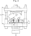
- Fig.2 is a schematic sectional view of another example of a pair of molds used in the method of the present invention.
- Fig.3 is a timing chart which shows working of the molds, the hollow pins and others in one example of the method of the present invention.
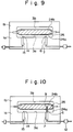
- Figs.4, 5 and 9 to 12 are schematic sectional views which show the states in the various steps of the method of producing a hollow molded article having skin materials on the whole surface thereof using the molds shown in Fig.1.
- Fig.6 is a schematic sectional view which shows an example of supplying a molten thermoplastic resin in the form of a rod in the method of the present invention.
- Fig.7 is a schematic sectional view which shows an example of supplying a molten thermoplastic resin in the form of a sheet in the method of the present invention.
- Fig.8 is a schematic sectional view which shows an example of supplying a molten thermoplastic resin in the form of a parison in the method of the present invention.
- Fig.13 is a timing chart which shows working of the molds, the hollow pins and others in another example of the method of the present invention.
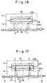
- Figs.14 to 19 are schematic sectional views which show the states in the various steps of the method of producing a hollow molded article having skin materials on the whole surface thereof using the molds shown in Fig.2.
- Figs.20 to 25 are schematic sectional views which show the states in the various steps of the method of producing a hollow molded article having a skin material on one side surface thereof using the molds shown in Fig.1.
- a pair of molds 1 used in the present invention comprises a first mold 1a and a second mold 1b, which are fitted to a pressing apparatus 2.
- the first mold 1a is provided at underside (the first mold 1a being lower mold or bottom mold), while the second mold 1b is provided at upper side (the second mold 1b being upper mold or top mold).
- the first mold 1a is attached to a fixed frame 2a of the pressing apparatus 2 (the first mold 1a being fixed mold), while the second mold 1b is attached to a movable frame 2c which is connected to the fixed frame 2a through connecting rods 2b (the second mold 1b being movable mold).
- the second mold 1b is movable in the direction of A (double ended arrow A) in Fig.1.
- the first mold may be the top mold and the second mold may be the bottom mold. Further, the first mold may be the movable mold and the second mold may be the fixed mold or both the molds may be the movable molds.
- the first mold 1a and the second mold 1b have cavity faces 3a and 3b respectively which conform to the configuration of the desired article and which oppose to each other.
- the cavity faces 3a and 3b form a cavity space which conforms to the configuration of the desired molded article.
- parting faces 4a and 4b are formed around the cavity faces 3a and 3b, respectively.
- the parting faces 4a and 4b are surfaces for holding the skin material therebetween when the first mold 1a and the second mold 1b are closed as explained hereinafter.
- a first hole 5 communicating with cavity face 3a is formed in the first mold 1a, and the first hollow pin 6 and the first driving device 7 are put in the first hole 5.
- the first hollow pin 6 is movable by means of the driving device 7 in the direction of B (as shown by double ended arrow B) in Fig.1 and movable between one position when it is fully put in the first hole 5 and another position when it is projected from the cavity face 3a (Fig.1 shows the state when the hollow pin 6 is projected).
- the first hollow pin 6 has therein a gas passage 8 through which gas passes and has at the tip portion thereof an opening 9 communicating with the gas passage 8.
- a gas-supplying device 11 is connected to the gas passage 8 through a gas-supplying pipe 10, and a first gas-supplying valve 12 is provided at the gas-supplying pipe 10. Therefore, supply of gas from the first hollow pin 6 and supply pressure of the gas can be adjusted by operating the gas-supplying valve 12.
- a second hole 13 communicating with cavity face 3a is formed in the first mold 1a, and the second hollow pin 14 and the second driving device 15 are put in the second hole 13.
- the second hollow pin 14 is movable by the driving device 15 in the direction of C (as shown by double ended arrow C) in Fig.1 and movable between one position when it is fully put in the second hole 13 and another position when it is projected from the cavity face 3a (Fig.1 shows the state when the hollow pin 14 is projected).
- the second hollow pin 14 has therein a gas passage 16 through which gas passes and has at the tip portion thereof an opening 17 communicating with the gas passage 16.
- a gas-discharging pipe 18 is connected to the gas passage 16 and a pressure-control valve 19 is provided at the gas-discharging pipe 18. Another end of the gas-discharging pipe 18 is open to the air. Therefore, gas can be discharged from the second hollow pin 14, and the pressure of discharging the gas from the second hollow pin 14 can be adjusted by operating the pressure-control valve 19.
- a controlling device 20 is connected to the first driving device 7, the second driving device 15 and the gas-supply valve 12 to control these devices.
- the controlling device 20 the first hollow pin 6 and the second hollow pin 14 are controlled so that they are projected from the cavity face 3a at the time of forming the hollow part and cooling the resin explained hereinafter and they are put in the mold 1a after completion of molding.
- the first hollow pin 6 and the second hollow pin 14 may be provided at the second mold 1b or both the molds 1a and 1b. Further, the first hollow pin 6 and the second hollow pin 14 may be provided separately at the first mold 1a and the second mold 1b, respectively, but generally both the hollow pins 6 and 14 are provided at the fixed mold.
- the number of the first hollow pin 6 and that of the second hollow pin 14 are optionally selected depending on the size and shape of the desired molded articles, but at least one pin 6 and at least one pin 14 are necessary, respectively.
- the number of the first hollow pin 6 and that of the second hollow pin 14 are not necessarily the same.
- the position of the first hollow pin and that of the second hollow pin 14 are not especially limited, but for enhancement of cooling efficiency, it is preferred that they are positioned in optional combination depending on the size and shape of the desired hollow molded articles so that when gas is discharged-from the second hollow pin 14 while gas is injected from the first hollow pin 6, the gas supplied into the hollow part can easily flow in the hollow part without causing partial staying of the gas.
- the first hollow pin 6 and the second hollow pin 14 are each in the form of a tube having a closed tip and preferably they are as thin as possible and have a sharp tip in order to make easier to pierce through the skin material and in order to make smaller the marks of the pin which would be left in the molded article after the hollow pin is drawn out.
- the opening 9 of the first hollow pin 6 is usually provided in the vicinity of the tip of the hollow pin in the direction perpendicular to the moving direction (B) of the pin 6 in plural numbers so as to discharge the gas in all directions, and typically, four openings are provided at an interval of 90°.
- the size, number and position of the opening can be optionally selected depending on the conditions such as thickness of the hollow pin, number and position of the hollow pin provided, amount of the gas injected and shape of the desired molded article.
- the opening 17 of the second hollow pin 14 may be the same as the opening 9 of the first hollow pin 6, but the size, etc. are optional as far as gas can be discharged therethrough.
- the driving devices 7 and 15 are not particularly restricted and, for example, there may be employed air or hydraulic driving devices or solenoid driving devices.
- the gas-supplying valve 12 and the pressure-control valve 19 are also not particularly restricted and, for example, solenoid valves may be used.
- the first mold 1a and the second mold 1b shown in Fig.1 are both so-called female molds where the cavity faces 3a and 3b are formed as a concave, but one of the molds may be so-called male mold where the cavity face is formed as a convex.
- the first hollow pin 6 is exclusively used for gas-supplying and the second hollow pin 14 is exclusively used for gas-discharging, but the second hollow pin 14 may have both the functions of gas-supplying and gas-discharging.
- Fig.2 shows another example of the molds having such second hollow pin 14 having both the functions of gas-supplying and gas-discharging.
- the gas-supplying pipe 10 connected to the first hollow pin 6 and the gas-discharging pipe 18 connected to the second hollow pin 14 are connected with each other through a gas conduit pipe 21.
- a second gas-supply valve 22 is provided at the gas conduit pipe 21 and a gas-discharge valve 23 is provided at the gas-discharging pipe 18.
- a controlling device 20 is connected to the first driving device 7, the second driving device 15, the first gas-supply valve 12, the second gas-supplying valve 22 and the gas-discharge valve 23 to control these devices.
- the second hollow pin 14 can be switched from the gas-supplying state to the gas-discharging state by changing the state of the second gas-supply valve 22 being opened and the gas-discharge valve 23 being closed to the state of the second gas-supplying valve 22 being closed and the gas-discharging valve 23 being opened using the controlling device 20.
- the pressure-control valve 19 may be used as the gas-discharge valve 23.
- the first skin material 24a is provided on the first mold 1a to cover the cavity face 3a and parting face 4a of the first mold 1a and the second skin material 24b is provided on the second mold 1b to cover the cavity face 3b and parting face 4b of the second mold 1b (shown in Fig.4).
- the skin materials 24a and 24b are provided so that the end portions thereof cover the parting faces 4a and 4b, respectively.
- the skin material when the mold is of female structure, preferably the skin material is not sagged (kept straight) and the end portions thereof are previously fixed on the parting face of the mold as shown in Fig.4.
- the molten thermoplastic resin cannot be enclosed or wrapped with the skin materials without a space between the resin and the skin material at the subsequent step of closing and, therefore, this is not preferred.
- Fixing of the skin material onto the parting face can be carried out by optional methods such as a method using a frame for holding the skin material.
- a fixing method using a pressure sensitive adhesive double coated tape may be employed.
- the skin material is placed in such a manner that it is put on the cavity face and the end portions thereof cover the parting face of the mold as shown in Fig.6.
- the skin materials used here are optionally selected depending on the uses thereof such as surface decoration of the hollow molded article, cushioning, heat insulators, etc., but they must have such a heat resistance as not melting or breaking by the heat of the molten thermoplastic resin. Thickness of the skin material varies depending on the kind of the skin material and usually is about 0.3-4 mm.
- the skin materials are exemplified by sheet or film of thermoplastic resins, sheet or film of thermoplastic elastomers, thermoplastic resin foamed sheet, thermoplastic elastomer foamed sheet, nonwoven fabric, knitted fabric, and laminates comprising a combination thereof.
- thermoplastic resins sheet or film of thermoplastic elastomers
- thermoplastic resin foamed sheet thermoplastic resin foamed sheet
- thermoplastic elastomer foamed sheet nonwoven fabric, knitted fabric, and laminates comprising a combination thereof.
- nonwoven fabric e.g., woven fabric, knitted fabric, and laminates comprising a combination thereof.
- knitted fabric knitted fabric
- laminates comprising a combination thereof.
- extensible skin materials preferred are preferred.
- the surface of the skin materials may be decorated with uneven patterns (such as grain patterns), printing, and the like. Further, depending on the uses of the desired molded articles, the first skin material 24a and the second skin material 24b may be the same, or different from each other.
- thermoplastic resin 25 is supplied between the first skin material 24a and the second skin material 24b which cover the cavity faces 3a and 3b, respectively, by a resin extruder or the like (shown in Fig.5).
- the molten resin 25 may be supplied in the form of a rod from a supply opening of a resin-supplying device 26 which is provided outside the molds, as shown in Fig.6.
- molten resin 25 may be extruded in the form of a sheet from T-die 27 provided at the head of resin-supplying device 26, as shown in Fig.7.
- molten resin 25 may be extruded in the form of a hollow (in the form of a parison) from parison die 28 provided at the end of resin-supplying device 26, as shown in Fig.8.
- the supply method of resin 25 is optionally selected depending on the shape of the cavity and the shape of the desired hollow molded article, but, when the hollow molded article is in the form of a pipe, the resin is preferably supplied in the form of a rod and, when the hollow molded article is in the form of nearly a flat plate, the resin is preferably supplied in the form of a sheet. Further, when a molded article having a skin material on only one side surface thereof is produced as explained hereinafter, the resin is preferably supplied in the form of a parison. In all of these resin supply methods, it is desired to supply the resin uniformly between the skin materials provided on the cavity faces with moving the molten resin-supply opening and/or moving the mold.
- Amount of the molten thermoplastic resin 25 supplied varies depending on the volume to be occupied by the hollow part in the desired hollow molded article, but usually is in the range of 5-50 vol% of the volume of cavity to be defined by the cavity faces 3a and 3b of the molds 1a and 1b.
- thermoplastic resins used here include general thermoplastic resins such as polyethylene, polypropylene, polystyrene, acrylonitrile-styrene-butadiene copolymer, polyvinyl chloride, polyamide, polycarbonate, polyethylene terephthalate, polybutylene terephthalate, polyphenylene ether and styrene-acrylonitrile copolymer; thermoplastic elastomers such as EPM and EPDM; mixtures thereof; and polymer alloys thereof.
- general thermoplastic resins such as polyethylene, polypropylene, polystyrene, acrylonitrile-styrene-butadiene copolymer, polyvinyl chloride, polyamide, polycarbonate, polyethylene terephthalate, polybutylene terephthalate, polyphenylene ether and styrene-acrylonitrile copolymer
- thermoplastic elastomers such as EPM and EPDM
- thermoplastic resins may contain inorganic fillers such as talc, wollastonite or glass fibers and may naturally contain various customary additives such as antioxidants and ultraviolet absorbers, or various colorants.
- the molten thermoplastic resin 25 is supplied between the skin materials 24a and 24b and, immediately thereafter, the second mold 1b is lowered to the position DOWN to close the molds 1a and 1b and the end portions of skin materials 24a and 24b are sandwiched between parting faces 4a and 4b of the molds to fix them (t1 in Fig.3), whereby the molten thermoplastic resin 25 supplied between skin materials 24a and 24b is wrapped therebetween with extending the skin materials and thus is in an enclosed state (shown in Fig.9).
- the first driving device 7 is worked (t2 in Fig.3) to allow the tip portion of the first hollow pin 6 to pierce through the first skin material 24a and to insert it into the molten thermoplastic resin 25 (shown in Fig.10).
- the first hollow pin 6 is projected in such a manner that the tip does not pierce the second skin material 24b.
- the opening 9 of the first hollow pin 6 is positioned at nearly the center of molten resin layer 25 (nearly the center between skin material 24a and skin material 24b).
- the first gas-supply valve 12 is opened (t2 in Fig.3) to inject pressurized gas 29 from opening 9 of the first hollow pin 6.
- the injected pressurized gas 29 forms hollow part 30 and expands the molten resin 25 with extending skin materials 24a and 24b, whereby the skin materials 24a and 24b are brought into close contact with cavity faces 3a and 3b, and at the same time, there is formed a hollow molded article comprising thermoplastic resin 25 to which skin materials 24a and 24b are thermocompression bonded (shown in Fig.11).
- the pressurized gas used must have a pressure necessary to expand the molten thermoplastic resin 25 together with the skin materials 24a and 24b, the resin 25 being wrapped with the skin materials 24a and 24b and thus being in an enclosed state.
- the gas is normally used in a state pressurized to 2-10 kg/cm2.
- gas examples include air, nitrogen and the like. Air is preferably used as the gas from the points of workability, economy and safety.
- the second driving device 15 is worked (t3 in Fig.3) to allow the tip portion of the second hollow pin 14 to pierce through the first skin material 24a and resin layer 25 and to insert the tip portion into the hollow part 30 (shown in Fig.12).
- gas is begun to be discharged through opening 17 of the second hollow pin 14.
- the gas is continuously supplied from the first hollow pin 6 while the gas is discharged from the second hollow pin 14, thereby to make the gas flow in the hollow part 30 and then to discharge the gas which has been heated by the heat of molten resin 25 into the atmosphere from opening 17 of the second hollow pin 14 through the pressure-control valve 19.
- the arrows in Fig.12 show the flow of the gas 29.
- the gas-discharging pressure and the gas-supplying pressure are controlled by pressure-control valve 19 and the first gas-supply valve 12, respectively, so that the gas-supplying pressure and the gas-discharging pressure can suitably balance while keeping an internal pressure of the hollow part 30 necessary to maintain the shape of the hollow part.
- Such internal pressure is preferably 2-10 kg/cm2.
- the flow of gas is generated in the hollow part 30, and, by injecting a gas lower in temperature than the resin 25 into the hollow part 30, the hollow body is efficiently and uniformly cooled from inside owing to circulation of the gas and thus the molten resin 25 solidifies in a short time.
- the first gas-supply valve 12 is closed to stop the supply of gas (t4 in Fig.3).
- the second mold 1b is elevated to the position UP to open the molds and the resulting hollow molded article having skin materials is then removed (t6 in Fig.3).
- the first hollow pin 6 and the second hollow pin 14 are fully put in the first hole 5 and the second hole 13 in the mold 1a, respectively (t5 in Fig.3).
- These hollow pins 6 and 14 may be fully put in the holes before opening of the molds or after removal of the article.
- the gas remaining in the hollow part 30 after stopping the supply of gas may be previously discharged from the second hollow pin 14 before removal of the article or may be spontaneously discharged from the fine holes left after the article is taken out and the hollow pins are drawn out.
- the hollow molded article may have marks left after the hollow pins 6 and 14 have been drawn out, but they can be made merely fine traces by employing hollow pins of as fine as possible. Furthermore, for some skin materials, the marks can be made apparently unrecognizable owing to their restoring force, etc.
- the first skin material 24a and the second skin material 24b are provided on the first mold 1a and the second mold 1b, respectively (shown in Fig.14), in the same manner as mentioned above, and then, molten thermoplastic resin 25 is supplied between the first skin material 24a and the second skin material 24b (shown in Fig.15).
- the second mold 1b is lowered to the position DOWN to close both the molds 1a and 1b (t1 in Fig.13), and thus, the molten thermoplastic resin 25 is in the state of being enclosed with the skin materials 24a and 24b (shown in Fig.16).
- the first driving device 7 and the second driving device 15 are worked (t2 in Fig.13) to allow the tip portions of the first hollow pin 6 and the second hollow pin 14 to pierce through the first skin material 24a thereby to insert the tip portions into the molten thermoplastic resin 25 (shown in Fig.17).
- first gas-supply valve 12 and the second gas-supply valve 22 are opened with the gas-discharge valve 23 being closed (t2 in Fig.13) to inject pressurized gas 29 from opening 9 of the first hollow pin 6 and opening 17 of the second hollow pin 14.
- the injected pressurized gas 29 forms hollow part 30 and expands the molten resin 25 with extending skin materials 24a and 24b, whereby the skin materials 24a and 24b are brought into close contact with cavity faces 3a and 3b, and at the same time, there is formed a hollow molded article comprising the thermoplastic resin 25 to which the skin materials 24a and 24b are thermocompression bonded (shown in Fig.18).
- the injection efficiency of the pressurized gas is improved, but a partition wall 31 of the resin is formed between these hollow pins.
- the thickness and the position of the partition wall 31 formed remarkably vary depending upon a difference between the pressures of supplying gas from the hollow pins, as well as a difference between the times of starting gas-supply from the hollow pins.
- the gas is continuously supplied from the first hollow pin 6 with discharging the gas from the second hollow pin 14, and, as a result, the hollow body is efficiently and uniformly cooled from the inside by circulation of the gas having a low temperature in the hollow part 30 and thus the molten resin 25 solidifies in a short time. Furthermore, the partition wall 31 of the resin is broken by such circulation of the gas.
- the first gas-supply valve 12 is closed to stop the supply of gas (t4 in Fig.13). Then, the second mold 1b is elevated to the position UP to open the molds and then the resulting hollow molded article having skin materials is removed (t6 in Fig.13). After supply of the gas is stopped, the first hollow pin 6 and the second hollow pin 14 are fully put in the first hole 5 and the second hole 13 in the mold 1a, respectively (t5 in Fig.13). In this way, a hollow molded article having skin materials applied to the whole surface thereof is obtained.
- the second hollow pin is constructed as that having both the functions of gas-supplying and gas-discharging as mentioned above, the total number of the hollow pins diminishes and hence, marks of the hollow pins preferably diminish.
- a hollow molded article having skin materials applied to the whole surface thereof has been explained hereinabove, but according to the present invention, a hollow molded article having a skin material applied to only one side surface thereof can also be produced.
- production of a hollow molded article having a skin material applied to only one side surface thereof using the molds shown in Fig.1 will be explained referring to Figs.20-25.
- first skin material 24a is provided on the first mold 1a in the open state (shown in Fig.20) in the same manner as mentioned above, and then, molten thermoplastic resin 25 is supplied between the first skin material 24a and cavity face 3b of the second mold 1b (shown in Fig.21). Immediately thereafter, both the molds 1a and 1b are closed.
- the first driving device 7 is worked to allow the tip portion of the first hollow pin 6 to pierce through the first skin material 24a thereby to insert the tip portion into the molten thermoplastic resin 25 (shown in Fig.23).
- the first gas-supply valve 12 is opened to inject pressurized gas 29 from opening 9 of the first hollow pin 6.
- the injected pressurized gas 29 forms hollow part 30 and expands the skin material 24a and the molten resin 25, whereby the skin material 24a and the molten resin 25 are brought into close contact with the cavity faces 3a and 3b, respectively.
- a hollow molded article comprising the thermoplastic resin 25 to which the skin material 24a is thermocompression bonded (shown in Fig.24).
- the supply of the gas is stopped and the molds are opened to remove the resulting hollow molded article having a skin material. In this way, a hollow molded article having a skin material applied to one side surface thereof is obtained.
- the hollow molded article having a skin material can be efficiently cooled by a simple apparatus and a simple operation without using the conventional complicated apparatuses or special cooling materials.
- the resin hollow molded article can be cooled uniformly and in a short time without temporary reduction of pressure in the hollow part and thus, a hollow molded article having a skin material free of distortion can be obtained.
- thermoplastic resin hollow molded articles having a skin material which is not restricted by the resin used and can be readily controlled in the wall thickness to give a uniform wall thickness and the method can be applied to articles having a shape of high blow ratio.
- hollow molded articles having hollow ribs can be produced by selecting molding conditions and the resulting hollow molded articles are light in weight and can be employed for various uses.
- the skin materials and the thermoplastic resins used in the examples are as follows:
- thermoplastic resin hollow molded article having skin materials on the whole surface thereof was produced using the molding machine shown in Fig.1 by the steps shown in Figs.4, 5 and 9 to 12 in accordance with the time chart shown in Fig.3.
- the first skin material 24a was stretched to cover cavity face 3a of the first mold 1a in an open state and both ends of the skin material were fixed onto parting face 4a by a pressure sensitive adhesive double coated tape.
- the second skin material 24b was stretched to cover cavity face 3b of the second mold 1b and both ends of the skin material were fixed onto parting face 4b by a pressure sensitive adhesive double coated tape (shown in Fig.4).
- the first hollow pin 6 and the second hollow pin 14 were put or received in the first mold 1a.
- Polypropylene resin 25 molten at 230'C in an amount of 40 vol% based on the cavity volume was uniformly supplied onto the first skin material 24a stretched over the cavity face 3a of the first mold 1a from T-die 27 provided at the tip of portable extruder 26 which was moved horizontally (shown in Figs.5 and 7).
- the second mold 1b was lowered to close both the molds 1a and 1b to enclose the molten resin 25 with both the skin materials 24a and 24b (shown in Fig.9).
- the first hollow pin 6 was projected from the cavity face 3a of the first mold 1a and the tip portion of the pin 6 was inserted in the molten resin 25 by piercing it through the skin material 24a in such a manner that the opening 9 of the pin 6 was positioned at nearly the center between the skin materials 24a and 24b (shown in Fig.10).
- pressurized air 29 room temperature
- a pressure of 10 kg/cm2 was injected into the molten resin 25 from the opening 9 (shown in Fig.11).
- the second hollow pin 14 was inserted in the formed hollow part 30 by piercing it through the skin material 24a and resin layer 25 after lapse of 15 seconds from the starting of the injection of air 29 from the opening 9, and the air in the hollow part 30 was discharged from opening 17 under a discharging pressure of 4.5 kg/cm2 to cause circulation of air in the hollow part 30 (shown in Fig.12).
- the second mold 1b was elevated to open the molds, and then a hollow molded article having two skin materials on the upper and under surfaces thereof was taken out from the molds.
- the resulting hollow molded article was free from distortion and had a good appearance.
- Presence or absence of the distortion was determined in the following manner. That is, the hollow molded article was put on a horizontal table with the side of the polypropylene sheet facing upward, and when there was a space between the surface of the table and the under surface of the hollow molded article, the molded article was regarded to have a distortion.
- a hollow molded article was produced in the same manner as in Example 1, except that the discharging of air was not carried out and the injection time of the pressurized air was 35 seconds.
- the resulting hollow molded article had a good appearance, but was considerably distorted and the desired shape could not be obtained. Further, the hollow molded article was not sufficiently cooled in the molds.
- a hollow molded article was produced in the same manner as in Example 1, except that the supplying time of the pressurized air was 35 seconds and supply of the gas from the first hollow pin 6 and discharge of the gas from the second hollow pin 14 were started at the same time.
- the hollow part was not sufficiently formed in the resulting molded article and the desired shape was not obtained.
- thermoplastic resin hollow molded article having skin materials on the whole surface thereof was produced using the molding machine shown in Fig.2 by the steps shown in Figs.14 to 19 in accordance with the time chart shown in Fig.13.
- the resulting hollow molded article had no distortion and had good appearance as in Example 1. Further, there is no partition wall of the resin in the hollow part in the resulting article.
- thermoplastic resin hollow molded article having a skin material on one side surface thereof was produced using the molding machine shown in Fig.1 by the steps shown in Figs.20 to 25 in accordance with the time chart shown in Fig.3.
- the resulting hollow molded article had no distortion and had good appearance as in Example 1.
Landscapes
- Engineering & Computer Science (AREA)
- Mechanical Engineering (AREA)
- Manufacturing & Machinery (AREA)
- Physics & Mathematics (AREA)
- Thermal Sciences (AREA)
- Chemical & Material Sciences (AREA)
- Composite Materials (AREA)
- Blow-Moulding Or Thermoforming Of Plastics Or The Like (AREA)
- Injection Moulding Of Plastics Or The Like (AREA)
- Moulds For Moulding Plastics Or The Like (AREA)
Applications Claiming Priority (2)
| Application Number | Priority Date | Filing Date | Title |
|---|---|---|---|
| JP6112983A JPH07314541A (ja) | 1994-05-26 | 1994-05-26 | 表皮材を貼合した中空成形体の製造方法 |
| JP112983/94 | 1994-05-26 |
Publications (3)
| Publication Number | Publication Date |
|---|---|
| EP0684119A2 true EP0684119A2 (de) | 1995-11-29 |
| EP0684119A3 EP0684119A3 (de) | 1995-12-13 |
| EP0684119B1 EP0684119B1 (de) | 1998-02-11 |
Family
ID=14600473
Family Applications (1)
| Application Number | Title | Priority Date | Filing Date |
|---|---|---|---|
| EP95303572A Expired - Lifetime EP0684119B1 (de) | 1994-05-26 | 1995-05-25 | Verfahren zum Herstellen eines mit einem Oberflächenmaterial versehenen Hohlkörpers |
Country Status (3)
| Country | Link |
|---|---|
| EP (1) | EP0684119B1 (de) |
| JP (1) | JPH07314541A (de) |
| DE (1) | DE69501602T2 (de) |
Cited By (7)
| Publication number | Priority date | Publication date | Assignee | Title |
|---|---|---|---|---|
| EP0745468A1 (de) * | 1995-05-30 | 1996-12-04 | Bauer Engineering GmbH | Formwerkzeug, insbesondere für das Kunststoffspritzgiessen mittels Gasinnendruck und Verfahren zur Herstellung von Kunststoff-Spritzgussformteilen unter Einsatz des Formwerkzeugs |
| US6106260A (en) * | 1995-03-03 | 2000-08-22 | Sumitomo Chemical Company, Limited | Mold useful in the production of hollow thermoplastic molded articles |
| EP1070576A3 (de) * | 1999-07-17 | 2003-02-19 | The University of Warwick | Verfahren und Vorrichtung zum Formen mit Gaseinspritzung |
| FR2838670A1 (fr) * | 2002-04-22 | 2003-10-24 | Renault Sa | Procede et dispositif de moulage par injection d'une piece creuse en matiere plastique |
| US7553554B2 (en) | 2004-05-27 | 2009-06-30 | Jarden Zinc Products, LLC | Environmentally protected reinforcement dowel pins and method of making |
| ITFI20090068A1 (it) * | 2009-04-02 | 2010-10-03 | Bini S R L | "stampo di formatura di articoli in materia plastica per soffiaggio" |
| CN108297329A (zh) * | 2018-01-25 | 2018-07-20 | 浙江普利斐特汽车科技有限公司 | 一种车用高弹性pvc密封材料加工设备 |
Families Citing this family (3)
| Publication number | Priority date | Publication date | Assignee | Title |
|---|---|---|---|---|
| KR101692132B1 (ko) * | 2015-01-09 | 2017-01-02 | 주식회사 동희산업 | 플라스틱 연료탱크의 제조장치 |
| JP6853073B2 (ja) * | 2017-03-10 | 2021-03-31 | 株式会社Fts | ブロー成形方法 |
| CN109622775A (zh) * | 2018-12-18 | 2019-04-16 | 洛阳冠驰精工科技有限公司 | 一种冷却循环钣金加工设备 |
Citations (3)
| Publication number | Priority date | Publication date | Assignee | Title |
|---|---|---|---|---|
| JPH04255314A (ja) | 1991-02-08 | 1992-09-10 | Sumitomo Chem Co Ltd | 中空成形品の製造方法 |
| JPH04267124A (ja) | 1991-02-21 | 1992-09-22 | Toyoda Gosei Co Ltd | 樹脂中空成形品の製造方法 |
| US5154872A (en) | 1988-03-16 | 1992-10-13 | Sumitomo Chemical Company, Limited | Process for producing a multilayer molded article |
Family Cites Families (4)
| Publication number | Priority date | Publication date | Assignee | Title |
|---|---|---|---|---|
| US3488801A (en) * | 1966-07-05 | 1970-01-13 | Phillips Petroleum Co | Movable blow pin for directional cooling |
| DE3742457A1 (de) * | 1987-12-15 | 1989-06-29 | Dynamit Nobel Ag | Herstellverfahren fuer kunststoff-formteile mit dekorativ-gepraegter oberflaechenbeschichtung |
| US5127814A (en) * | 1990-11-26 | 1992-07-07 | Nitrojection Corporation | Apparatus for producing a fluid-assisted injection molded product |
| US5229043A (en) * | 1992-03-10 | 1993-07-20 | The Boc Group, Inc. | Blow molding method and apparatus employing pressurized liquid cryogen vaporized by recovered gaseous cryogen |
-
1994
- 1994-05-26 JP JP6112983A patent/JPH07314541A/ja active Pending
-
1995
- 1995-05-25 EP EP95303572A patent/EP0684119B1/de not_active Expired - Lifetime
- 1995-05-25 DE DE69501602T patent/DE69501602T2/de not_active Expired - Fee Related
Patent Citations (4)
| Publication number | Priority date | Publication date | Assignee | Title |
|---|---|---|---|---|
| US5154872A (en) | 1988-03-16 | 1992-10-13 | Sumitomo Chemical Company, Limited | Process for producing a multilayer molded article |
| JPH04255314A (ja) | 1991-02-08 | 1992-09-10 | Sumitomo Chem Co Ltd | 中空成形品の製造方法 |
| US5277865A (en) | 1991-02-08 | 1994-01-11 | Sumitomo Chemical Company, Limited | Gas-assisted injection molding process for producing hollow molded article |
| JPH04267124A (ja) | 1991-02-21 | 1992-09-22 | Toyoda Gosei Co Ltd | 樹脂中空成形品の製造方法 |
Cited By (9)
| Publication number | Priority date | Publication date | Assignee | Title |
|---|---|---|---|---|
| US6106260A (en) * | 1995-03-03 | 2000-08-22 | Sumitomo Chemical Company, Limited | Mold useful in the production of hollow thermoplastic molded articles |
| US6506335B1 (en) | 1995-03-03 | 2003-01-14 | Sumitomo Chemical Company, Limited | Mold for production of hollow thermoplastic resin molded article, and process for production of hollow thermoplastic resin molded article using the same |
| EP0745468A1 (de) * | 1995-05-30 | 1996-12-04 | Bauer Engineering GmbH | Formwerkzeug, insbesondere für das Kunststoffspritzgiessen mittels Gasinnendruck und Verfahren zur Herstellung von Kunststoff-Spritzgussformteilen unter Einsatz des Formwerkzeugs |
| EP1070576A3 (de) * | 1999-07-17 | 2003-02-19 | The University of Warwick | Verfahren und Vorrichtung zum Formen mit Gaseinspritzung |
| US6869562B1 (en) | 1999-07-17 | 2005-03-22 | University Of Warwick | Gas injection moulding method and apparatus |
| FR2838670A1 (fr) * | 2002-04-22 | 2003-10-24 | Renault Sa | Procede et dispositif de moulage par injection d'une piece creuse en matiere plastique |
| US7553554B2 (en) | 2004-05-27 | 2009-06-30 | Jarden Zinc Products, LLC | Environmentally protected reinforcement dowel pins and method of making |
| ITFI20090068A1 (it) * | 2009-04-02 | 2010-10-03 | Bini S R L | "stampo di formatura di articoli in materia plastica per soffiaggio" |
| CN108297329A (zh) * | 2018-01-25 | 2018-07-20 | 浙江普利斐特汽车科技有限公司 | 一种车用高弹性pvc密封材料加工设备 |
Also Published As
| Publication number | Publication date |
|---|---|
| JPH07314541A (ja) | 1995-12-05 |
| EP0684119B1 (de) | 1998-02-11 |
| DE69501602D1 (de) | 1998-03-19 |
| DE69501602T2 (de) | 1998-06-18 |
| EP0684119A3 (de) | 1995-12-13 |
Similar Documents
| Publication | Publication Date | Title |
|---|---|---|
| US20040004313A1 (en) | Process for gas assisted and water assisted injection molding | |
| KR0165919B1 (ko) | 사출연신취입성형에 있어서의 프리포옴 성형방법 | |
| US4783292A (en) | Method of injection molding a foamed plastic article using a relatively light gas as a blowing agent | |
| US5366674A (en) | Process for producing expanded plastics with skin | |
| EP0684119B1 (de) | Verfahren zum Herstellen eines mit einem Oberflächenmaterial versehenen Hohlkörpers | |
| EP0498444B1 (de) | Verfahren zur Herstellung eines geformten Hohlkörpers | |
| US4636349A (en) | Process for manufacturing thermoplastic containers | |
| US6759003B1 (en) | Blow molding method, blow molded product and blow molding mold | |
| CA2086106C (en) | Mold for press molding and process for press molding of thermoplastic resin using the same | |
| JPH04212823A (ja) | 多層成形品の製造方法 | |
| JP2001001391A (ja) | ガラス繊維強化樹脂製中空成形品のブロー成形方法 | |
| JPH1034723A (ja) | 射出成形装置 | |
| KR100706424B1 (ko) | 자동차용 도어트림의 성형장치 및 성형방법 | |
| JP2002219737A (ja) | 微細凹凸形状を有する成形品の製造方法及びそれに用いる金型装置 | |
| EP0633121B1 (de) | VERFAHREN ZUR HERSTELLUNG VON HOHLEN FORMKöRPERN | |
| JPH06198725A (ja) | 中空プラスチック製品の調整用装置 | |
| CN116985329A (zh) | 热塑性高分子材料一次物理发泡成型的加工方法及其装置 | |
| JP2002160224A (ja) | 熱可塑性樹脂軽量成形体製造用金型およびこれを用いた熱可塑性樹脂軽量成形体の製造方法 | |
| EP0884156B1 (de) | Verfahren zum Herstellen von thermoplastischen gegossenen Kunststoffhohlkörpern | |
| JP3858408B2 (ja) | 多層成形品成形用金型 | |
| JPH11138592A (ja) | 加飾成形用金型の雌型 | |
| JP3337752B2 (ja) | スタンピング形成方法 | |
| KR100517596B1 (ko) | 플라스틱 발포 사출 방법 | |
| EP0787570B1 (de) | Verfahren zur Herstellung eines Hohlkörpers | |
| JP2807980B2 (ja) | 中空射出成形品の製造方法 |
Legal Events
| Date | Code | Title | Description |
|---|---|---|---|
| PUAI | Public reference made under article 153(3) epc to a published international application that has entered the european phase |
Free format text: ORIGINAL CODE: 0009012 |
|
| PUAL | Search report despatched |
Free format text: ORIGINAL CODE: 0009013 |
|
| AK | Designated contracting states |
Kind code of ref document: A2 Designated state(s): DE FR GB IT |
|
| AK | Designated contracting states |
Kind code of ref document: A3 Designated state(s): DE FR GB IT |
|
| 17P | Request for examination filed |
Effective date: 19960223 |
|
| 17Q | First examination report despatched |
Effective date: 19960531 |
|
| GRAG | Despatch of communication of intention to grant |
Free format text: ORIGINAL CODE: EPIDOS AGRA |
|
| GRAG | Despatch of communication of intention to grant |
Free format text: ORIGINAL CODE: EPIDOS AGRA |
|
| GRAH | Despatch of communication of intention to grant a patent |
Free format text: ORIGINAL CODE: EPIDOS IGRA |
|
| GRAH | Despatch of communication of intention to grant a patent |
Free format text: ORIGINAL CODE: EPIDOS IGRA |
|
| GRAA | (expected) grant |
Free format text: ORIGINAL CODE: 0009210 |
|
| AK | Designated contracting states |
Kind code of ref document: B1 Designated state(s): DE FR GB IT |
|
| ITF | It: translation for a ep patent filed | ||
| REF | Corresponds to: |
Ref document number: 69501602 Country of ref document: DE Date of ref document: 19980319 |
|
| ET | Fr: translation filed | ||
| PLBE | No opposition filed within time limit |
Free format text: ORIGINAL CODE: 0009261 |
|
| STAA | Information on the status of an ep patent application or granted ep patent |
Free format text: STATUS: NO OPPOSITION FILED WITHIN TIME LIMIT |
|
| 26N | No opposition filed | ||
| PGFP | Annual fee paid to national office [announced via postgrant information from national office to epo] |
Ref country code: FR Payment date: 20010518 Year of fee payment: 7 |
|
| PGFP | Annual fee paid to national office [announced via postgrant information from national office to epo] |
Ref country code: DE Payment date: 20010522 Year of fee payment: 7 |
|
| PGFP | Annual fee paid to national office [announced via postgrant information from national office to epo] |
Ref country code: GB Payment date: 20010523 Year of fee payment: 7 |
|
| REG | Reference to a national code |
Ref country code: GB Ref legal event code: IF02 |
|
| PG25 | Lapsed in a contracting state [announced via postgrant information from national office to epo] |
Ref country code: GB Free format text: LAPSE BECAUSE OF NON-PAYMENT OF DUE FEES Effective date: 20020525 |
|
| PG25 | Lapsed in a contracting state [announced via postgrant information from national office to epo] |
Ref country code: DE Free format text: LAPSE BECAUSE OF NON-PAYMENT OF DUE FEES Effective date: 20021203 |
|
| GBPC | Gb: european patent ceased through non-payment of renewal fee |
Effective date: 20020525 |
|
| PG25 | Lapsed in a contracting state [announced via postgrant information from national office to epo] |
Ref country code: FR Free format text: LAPSE BECAUSE OF NON-PAYMENT OF DUE FEES Effective date: 20030131 |
|
| REG | Reference to a national code |
Ref country code: FR Ref legal event code: ST |
|
| PG25 | Lapsed in a contracting state [announced via postgrant information from national office to epo] |
Ref country code: IT Free format text: LAPSE BECAUSE OF NON-PAYMENT OF DUE FEES Effective date: 20050525 |