EP0684416A1 - Mélangeur à eau avec dispositif non-retour intégré - Google Patents
Mélangeur à eau avec dispositif non-retour intégré Download PDFInfo
- Publication number
- EP0684416A1 EP0684416A1 EP95830212A EP95830212A EP0684416A1 EP 0684416 A1 EP0684416 A1 EP 0684416A1 EP 95830212 A EP95830212 A EP 95830212A EP 95830212 A EP95830212 A EP 95830212A EP 0684416 A1 EP0684416 A1 EP 0684416A1
- Authority
- EP
- European Patent Office
- Prior art keywords
- water
- valve
- outlet opening
- mixer valve
- breather hole
- Prior art date
- Legal status (The legal status is an assumption and is not a legal conclusion. Google has not performed a legal analysis and makes no representation as to the accuracy of the status listed.)
- Withdrawn
Links
- XLYOFNOQVPJJNP-UHFFFAOYSA-N water Substances O XLYOFNOQVPJJNP-UHFFFAOYSA-N 0.000 title claims abstract description 83
- 238000009428 plumbing Methods 0.000 claims abstract description 5
- 230000000694 effects Effects 0.000 claims abstract 3
- 239000013013 elastic material Substances 0.000 claims description 3
- 238000004873 anchoring Methods 0.000 claims description 2
- 230000002093 peripheral effect Effects 0.000 claims description 2
- 230000003068 static effect Effects 0.000 claims description 2
- 230000000284 resting effect Effects 0.000 claims 1
- 230000033228 biological regulation Effects 0.000 description 2
- 239000000919 ceramic Substances 0.000 description 2
- 230000015572 biosynthetic process Effects 0.000 description 1
- 238000004891 communication Methods 0.000 description 1
- 230000008602 contraction Effects 0.000 description 1
- 230000009977 dual effect Effects 0.000 description 1
- 230000005764 inhibitory process Effects 0.000 description 1
- 239000000463 material Substances 0.000 description 1
- 238000000034 method Methods 0.000 description 1
- 230000001960 triggered effect Effects 0.000 description 1
Images


Classifications
-
- F—MECHANICAL ENGINEERING; LIGHTING; HEATING; WEAPONS; BLASTING
- F16—ENGINEERING ELEMENTS AND UNITS; GENERAL MEASURES FOR PRODUCING AND MAINTAINING EFFECTIVE FUNCTIONING OF MACHINES OR INSTALLATIONS; THERMAL INSULATION IN GENERAL
- F16K—VALVES; TAPS; COCKS; ACTUATING-FLOATS; DEVICES FOR VENTING OR AERATING
- F16K11/00—Multiple-way valves, e.g. mixing valves; Pipe fittings incorporating such valves
- F16K11/02—Multiple-way valves, e.g. mixing valves; Pipe fittings incorporating such valves with all movable sealing faces moving as one unit
- F16K11/06—Multiple-way valves, e.g. mixing valves; Pipe fittings incorporating such valves with all movable sealing faces moving as one unit comprising only sliding valves, i.e. sliding closure elements
- F16K11/078—Multiple-way valves, e.g. mixing valves; Pipe fittings incorporating such valves with all movable sealing faces moving as one unit comprising only sliding valves, i.e. sliding closure elements with pivoted and linearly movable closure members
- F16K11/0782—Single-lever operated mixing valves with closure members having flat sealing faces
Definitions
- the present invention pertains in general to mixer valves for hot and cold water, and more specifically to mixer valves to be used in taps for plumbing appliances in which an impediment is required, a so-called “vacuum breaker", for a non-return of the water towards the water supply system.
- mixer valves for hot and cold water comprise, within a cartridge body, valve means comprising at least two overlapping plates, in ceramics or the like, provided with separate inlet passages for hot water and for cold water and with one outlet opening for hot, cold or mixed water flowing towards the spout of a tap.
- One of said plates is fixed and another plate is mobile and displaceable on the first one by means of a manoeuvring lever to open/close the valve.
- hot water and cold water are conveyed to the inlet passages by means of adduction pipes connected to the bottom of the valve body; the water to be supplied comes out of the bottom or from a side of the cartridge body and is channelled to the tap spout.
- the spout may be a pull-out shower connected to a flexible hose which channells the water from the mixer valve and which can be handled within the framework of the plumbing appliance.
- safety regulations providing for a non-return of the water back from the appliance to the water supply system, a condition which may occur when the mixer valve is shut off while the shower supply is kept or left unwittingly immersed in a volume of water and which may be the cause of pollution of the water in the system.
- a pressure drop can be created in the water channel so as to cause suction through the shower and therefore a flow of water back-towards the supply system.
- Another object of the invention is to provide a mixer valve of the above mentioned type directly incorporating a non-return valve device, placed at the bottom of its cartridge body, at the level of the water inlet and/or outlet passages, advantageously without modifying the customary structure, dimensions, and method of using the valve.
- Yet another object of the invention is to provide a mixer valve able to perform a dual function of mixing and controlling the flow of water to be supplied and of non-return device of the water towards the supply system once distributed.
- An additional object of the invention is to provide a mixer valve that can be used advantageously also in applications for which safety regulations have to be observed that provide for mounting of a so-called “vacuum breaker", that is inhibition of any suction of water and therefore removal of a condition that may cause an undesired return of water towards the distribution system.
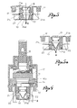
- the mixer valve designed to receive the present invention comprises a cartridge body which may comprise an upturned cup element 11 and a bottom 12 closing the cup element; said bottom may be configured to act also as a distributor of the water flowing out of the valve.
- the bottom 12 is provided with two separate inlet passages 13, 14 for hot and cold water and with an outlet opening 15 for hot, cold or mixed water as preferred.
- the inlet passages 13, 14 receive water from two pipes - not represented - which supply hot and cold water in the direction of the arrows C and F - see Fig. 2; the opening of outlet 15 communicates, in the direction of the arrow U, with a spout or a water supply channel for use.
- valve means which usually comprise overlapping plates, in ceramics or the like, of which the lower one 16 is fixed and rests on the bottom 12 and the upper 17 is mobile and can be moved on the fixed plate by means of a manoeuvring lever 18 to control opening and closing of the valve.
- the fixed plate 16 is provided with two inlet holes 16a, 16b coinciding with the water inlet holes 13, 14 on the bottom 12 of the cartridge body and with an outlet hole 16c coinciding with the outlet opening in said bottom 12.
- the mobile plate 17 has in its turn a mixing chamber 17a which can be positioned over the holes 16a, 16b, 16c of the fixed plate 16 to control supply of water.
- the mixer valve is equipped with a device D designed to inhibit the backflow of water from the point of use to the adduction pipes through the valve itself.
- said device D is applied in the water inlet holes 13, 14 provided in the bottom 12 of the cartridge body as shown in Figs. 1-3, 3a. It consists of two non-return valves 19, equal to each other, inserted respectively in said inlet holes 13, 14.
- Said non-return valves 19 are at least partially in an elastic, rubber, or similar material and may be obtained to form one integral piece - see Fig. 1 - with a seal 20 applied usually on the base of the bottom 12 around the water inlet and outlet passages.
- Each non-return valve 19 has anyhow a static tubular portion 19', which closely adapts to the internal surface of the passage 13 or 14 in which it is inserted, and an expanding and contracting conical portion 19", tapered in the direction of the incoming flows of H and C water.
- the non-return valves 19 move to a rest position in which they can stay slightly open at the level of their conical portion 19" as schematized in Fig. 2.
- the pressure and the flow of water flowing in through the inlet holes 13, 14 cause opening of the non-return valves, as shown in Fig. 3, for a regular supply of water towards the point of use.
- any drop in pressure that may be created in the system and that could cause suction of water from the point of use determines a contraction and therefore closure of the non-return valves at the level of their conical portions 19", as shown in Fig. 3a, which prevents the backflow of water towards the adduction pipes.
- the anti-backflow device D consists of a valve element 21 inserted in the outlet opening 15 in the bottom of the cartridge body of the mixer valve and designed to close and open at least one air bleeder 22 made in a radial direction to said water outlet opening 15.
- valve element 21 is in an elastic material, of a tubular shape and inserted in the outlet opening 15 with the possibility to expand and contract in the direction of its length.
- Said valve element 21 has, in order from the entrance to the exit of said outlet opening 15, a peripheral flange 21 a anchoring the opening element 15, a first intermediate bellows portion 21 b that can expand and contract longitudinally, a second intermediate interception portion 21 designed to close the breather hole 22, and a conical end portion 21 d, that can expand and contract transversely and is tapered in the direction of the flow of outflowing water according to the arrow U.
- valve element 21 stimulated by the flow and by the pressure of the water, extends and expands as shown in Fig. 5, thereby closing the air inlet.
- valve element contracts and closes up as shown in Fig. 5a, opening the air holes 22 and preventing backflow of the water.
- a floating ram - not represented - may be used, again with the purpose of closing the breather holes 22 during distribution of water and of opening them on closing the valve to cancel the formation of a pressure drop and to eliminate water backflow.
- the anti-backflow device D consists of a piston valve 23 placed in a breather hole 24 obtained in the bottom 12 of the cartridge body of the valve as shown in Figs. 6, 7 and 7a.
- the breather hole 22 puts the water outlet opening 15 of the valve in communication with the atmosphere, and in said hole there is a valve seat 25 on which the piston valve acts to close/open the hole itself.
- the piston is triggered by a spring 26 that keeps it normally pushed against the valve seat 25 in the position of the breather hole closed. With the piston valve 23 in this position - see Fig. 7 - the water can be supplied normally as soon as the mixer valve is opened, without any air getting in from the outside.
Landscapes
- Engineering & Computer Science (AREA)
- General Engineering & Computer Science (AREA)
- Mechanical Engineering (AREA)
- Multiple-Way Valves (AREA)
- Check Valves (AREA)
- Domestic Plumbing Installations (AREA)
Applications Claiming Priority (2)
| Application Number | Priority Date | Filing Date | Title |
|---|---|---|---|
| IT94BS000051A ITBS940051A1 (it) | 1994-05-24 | 1994-05-24 | Valvola miscelatrice di acqua calda e fredda con un dispositivo anti-reflusso incorporato |
| ITBS940051 | 1994-05-24 |
Publications (1)
| Publication Number | Publication Date |
|---|---|
| EP0684416A1 true EP0684416A1 (fr) | 1995-11-29 |
Family
ID=11345305
Family Applications (1)
| Application Number | Title | Priority Date | Filing Date |
|---|---|---|---|
| EP95830212A Withdrawn EP0684416A1 (fr) | 1994-05-24 | 1995-05-19 | Mélangeur à eau avec dispositif non-retour intégré |
Country Status (3)
| Country | Link |
|---|---|
| EP (1) | EP0684416A1 (fr) |
| JP (1) | JPH0854076A (fr) |
| IT (1) | ITBS940051A1 (fr) |
Cited By (4)
| Publication number | Priority date | Publication date | Assignee | Title |
|---|---|---|---|---|
| DE19702036A1 (de) * | 1997-01-22 | 1998-07-23 | Grohe Kg Hans | Sanitäres Mischventil |
| EP0881556A1 (fr) * | 1997-05-27 | 1998-12-02 | Emhart Inc. | Système d'équilibrage de pression pour robinetterie sanitaire à deux/trois poignées |
| WO2000005524A1 (fr) * | 1998-07-22 | 2000-02-03 | KEROX-MULTIPOLÁR II.Kfr. | Cartouche universelle pour mitigeur |
| DE102007011860A1 (de) | 2007-03-05 | 2008-09-18 | Hansgrohe Ag | Armaturengehäuse für eine Sanitärarmatur |
Families Citing this family (3)
| Publication number | Priority date | Publication date | Assignee | Title |
|---|---|---|---|---|
| JP2003074095A (ja) * | 2001-08-31 | 2003-03-12 | Kvk Corp | 残水逃し機構 |
| AU2014219082B2 (en) | 2013-02-20 | 2018-06-07 | Ecolab Usa Inc. | Global backflow prevention assembly |
| FR3124840B1 (fr) * | 2021-06-30 | 2023-07-07 | Vernet | Mitigeur sanitaire thermostatique, ainsi qu’ensemble modulaire de mitigeur sanitaire thermostatique |
Citations (6)
| Publication number | Priority date | Publication date | Assignee | Title |
|---|---|---|---|---|
| US2598002A (en) * | 1946-08-20 | 1952-05-27 | Jesse D Langdon | Check valve construction |
| US2675823A (en) * | 1949-09-07 | 1954-04-20 | Jesse D Langdon | Backflow preventer |
| US3556122A (en) * | 1964-06-15 | 1971-01-19 | Laerdal A S | Valve for artificial respiration apparatus |
| US3572375A (en) * | 1967-06-02 | 1971-03-23 | David Rosenberg | Twin valve t-connector |
| DE9214042U1 (de) * | 1992-01-17 | 1992-12-17 | Meloh-Armaturen GmbH, 5860 Iserlohn | Kartusche für Einhebel-Mischbatterien |
| DE4325256A1 (de) * | 1992-07-28 | 1994-02-03 | Masco Corp | Mischventil mit Druckausgleich |
-
1994
- 1994-05-24 IT IT94BS000051A patent/ITBS940051A1/it unknown
-
1995
- 1995-05-19 EP EP95830212A patent/EP0684416A1/fr not_active Withdrawn
- 1995-05-24 JP JP7125300A patent/JPH0854076A/ja active Pending
Patent Citations (6)
| Publication number | Priority date | Publication date | Assignee | Title |
|---|---|---|---|---|
| US2598002A (en) * | 1946-08-20 | 1952-05-27 | Jesse D Langdon | Check valve construction |
| US2675823A (en) * | 1949-09-07 | 1954-04-20 | Jesse D Langdon | Backflow preventer |
| US3556122A (en) * | 1964-06-15 | 1971-01-19 | Laerdal A S | Valve for artificial respiration apparatus |
| US3572375A (en) * | 1967-06-02 | 1971-03-23 | David Rosenberg | Twin valve t-connector |
| DE9214042U1 (de) * | 1992-01-17 | 1992-12-17 | Meloh-Armaturen GmbH, 5860 Iserlohn | Kartusche für Einhebel-Mischbatterien |
| DE4325256A1 (de) * | 1992-07-28 | 1994-02-03 | Masco Corp | Mischventil mit Druckausgleich |
Cited By (5)
| Publication number | Priority date | Publication date | Assignee | Title |
|---|---|---|---|---|
| DE19702036A1 (de) * | 1997-01-22 | 1998-07-23 | Grohe Kg Hans | Sanitäres Mischventil |
| EP0881556A1 (fr) * | 1997-05-27 | 1998-12-02 | Emhart Inc. | Système d'équilibrage de pression pour robinetterie sanitaire à deux/trois poignées |
| WO2000005524A1 (fr) * | 1998-07-22 | 2000-02-03 | KEROX-MULTIPOLÁR II.Kfr. | Cartouche universelle pour mitigeur |
| US7836913B1 (en) | 1998-07-22 | 2010-11-23 | Kerox-Multipolar Ii. Kft. | Universal cartridge for a mixer faucet |
| DE102007011860A1 (de) | 2007-03-05 | 2008-09-18 | Hansgrohe Ag | Armaturengehäuse für eine Sanitärarmatur |
Also Published As
| Publication number | Publication date |
|---|---|
| ITBS940051A0 (it) | 1994-05-24 |
| JPH0854076A (ja) | 1996-02-27 |
| ITBS940051A1 (it) | 1995-11-24 |
Similar Documents
| Publication | Publication Date | Title |
|---|---|---|
| CA2132135C (fr) | Robinets de derivation munis d'un dispositif anti-retour incorpore et d'un mecanisme de clapet de retenue a l'entree et a la sortie | |
| US3726317A (en) | Bottom outlet grommet mixing valve | |
| US6779554B2 (en) | Return check valve | |
| JPH03504823A (ja) | 流し台混合水栓またはこれに類似したもののためのシヤワーヘツド | |
| CA2289388C (fr) | Organe de derivation de robinet a pulverisateur lateral | |
| AU2004219971B2 (en) | Device for preventing backflow | |
| US4669497A (en) | Backflow preventing device | |
| US6748970B2 (en) | Pilot operated water conservation valve and actuator | |
| US5730173A (en) | Sanitary water valve | |
| KR100755488B1 (ko) | 급배수관 결합용 다통로 밸브 | |
| KR19980087042A (ko) | 2/3 핸들 압력 평형기 시스템 | |
| US2852034A (en) | Anti-siphon trap | |
| CA2291909C (fr) | Appareil pour ameliorer le siege d'une garniture de robinet | |
| JPH04213634A (ja) | 給水栓装置 | |
| WO1998006910A1 (fr) | Robinet de chasse d'eau ameliore a pression de reseau de ville | |
| FI4018047T3 (fi) | Stagnaatiohuuhteluventtiililaite | |
| EP1347104B1 (fr) | Soupape d'évacuation | |
| US6857446B1 (en) | Flow controlling dual hydrant | |
| JPH0854076A (ja) | 逆流防止装置付き混合栓 | |
| KR950033122A (ko) | 유체압 피스톤 발동기 | |
| KR100554723B1 (ko) | 파일롯-릴리프 밸브 | |
| US5355907A (en) | Automatic draining back flow preventer for use with hydrant | |
| JP4984338B2 (ja) | 温水洗浄装置の給水装置 | |
| KR200151567Y1 (ko) | 수도전용 자폐식 밸브장치 | |
| JPH0218425Y2 (fr) |
Legal Events
| Date | Code | Title | Description |
|---|---|---|---|
| PUAI | Public reference made under article 153(3) epc to a published international application that has entered the european phase |
Free format text: ORIGINAL CODE: 0009012 |
|
| AK | Designated contracting states |
Kind code of ref document: A1 Designated state(s): CH DE DK ES FR GB IT LI NL PT SE |
|
| STAA | Information on the status of an ep patent application or granted ep patent |
Free format text: STATUS: THE APPLICATION IS DEEMED TO BE WITHDRAWN |
|
| 18D | Application deemed to be withdrawn |
Effective date: 19960630 |