EP0684427B1 - Dispositif rotatif de transfert de chaleur - Google Patents
Dispositif rotatif de transfert de chaleur Download PDFInfo
- Publication number
- EP0684427B1 EP0684427B1 EP95401154A EP95401154A EP0684427B1 EP 0684427 B1 EP0684427 B1 EP 0684427B1 EP 95401154 A EP95401154 A EP 95401154A EP 95401154 A EP95401154 A EP 95401154A EP 0684427 B1 EP0684427 B1 EP 0684427B1
- Authority
- EP
- European Patent Office
- Prior art keywords
- ring
- cage
- charge
- sector
- effluent
- Prior art date
- Legal status (The legal status is an assumption and is not a legal conclusion. Google has not performed a legal analysis and makes no representation as to the accuracy of the status listed.)
- Expired - Lifetime
Links
- 230000004087 circulation Effects 0.000 claims description 6
- 238000000638 solvent extraction Methods 0.000 claims description 4
- 238000004891 communication Methods 0.000 claims description 3
- 238000003754 machining Methods 0.000 claims description 3
- 238000012856 packing Methods 0.000 claims description 3
- 239000000126 substance Substances 0.000 claims description 3
- 238000007514 turning Methods 0.000 claims description 3
- 238000004140 cleaning Methods 0.000 claims description 2
- 238000002347 injection Methods 0.000 claims description 2
- 239000007924 injection Substances 0.000 claims description 2
- 239000002184 metal Substances 0.000 claims description 2
- 239000011343 solid material Substances 0.000 claims description 2
- 210000003850 cellular structure Anatomy 0.000 claims 1
- 229910010293 ceramic material Inorganic materials 0.000 claims 1
- 230000001939 inductive effect Effects 0.000 claims 1
- 239000007789 gas Substances 0.000 description 9
- 230000004907 flux Effects 0.000 description 6
- 241000264877 Hippospongia communis Species 0.000 description 4
- 239000000919 ceramic Substances 0.000 description 3
- 238000000034 method Methods 0.000 description 3
- 241001417494 Sciaenidae Species 0.000 description 2
- VYPSYNLAJGMNEJ-UHFFFAOYSA-N Silicium dioxide Chemical compound O=[Si]=O VYPSYNLAJGMNEJ-UHFFFAOYSA-N 0.000 description 2
- 239000012530 fluid Substances 0.000 description 2
- 239000000463 material Substances 0.000 description 2
- 239000002245 particle Substances 0.000 description 2
- 238000007789 sealing Methods 0.000 description 2
- 238000000926 separation method Methods 0.000 description 2
- 238000007664 blowing Methods 0.000 description 1
- 230000001413 cellular effect Effects 0.000 description 1
- 238000006243 chemical reaction Methods 0.000 description 1
- 239000010438 granite Substances 0.000 description 1
- 239000003112 inhibitor Substances 0.000 description 1
- 230000001788 irregular Effects 0.000 description 1
- 238000009940 knitting Methods 0.000 description 1
- 230000003071 parasitic effect Effects 0.000 description 1
- 230000002093 peripheral effect Effects 0.000 description 1
- 238000006116 polymerization reaction Methods 0.000 description 1
- 239000000377 silicon dioxide Substances 0.000 description 1
- 238000011144 upstream manufacturing Methods 0.000 description 1
Images



Classifications
-
- F—MECHANICAL ENGINEERING; LIGHTING; HEATING; WEAPONS; BLASTING
- F23—COMBUSTION APPARATUS; COMBUSTION PROCESSES
- F23G—CREMATION FURNACES; CONSUMING WASTE PRODUCTS BY COMBUSTION
- F23G7/00—Incinerators or other apparatus for consuming industrial waste, e.g. chemicals
- F23G7/06—Incinerators or other apparatus for consuming industrial waste, e.g. chemicals of waste gases or noxious gases, e.g. exhaust gases
-
- F—MECHANICAL ENGINEERING; LIGHTING; HEATING; WEAPONS; BLASTING
- F23—COMBUSTION APPARATUS; COMBUSTION PROCESSES
- F23G—CREMATION FURNACES; CONSUMING WASTE PRODUCTS BY COMBUSTION
- F23G7/00—Incinerators or other apparatus for consuming industrial waste, e.g. chemicals
- F23G7/06—Incinerators or other apparatus for consuming industrial waste, e.g. chemicals of waste gases or noxious gases, e.g. exhaust gases
- F23G7/061—Incinerators or other apparatus for consuming industrial waste, e.g. chemicals of waste gases or noxious gases, e.g. exhaust gases with supplementary heating
- F23G7/065—Incinerators or other apparatus for consuming industrial waste, e.g. chemicals of waste gases or noxious gases, e.g. exhaust gases with supplementary heating using gaseous or liquid fuel
- F23G7/066—Incinerators or other apparatus for consuming industrial waste, e.g. chemicals of waste gases or noxious gases, e.g. exhaust gases with supplementary heating using gaseous or liquid fuel preheating the waste gas by the heat of the combustion, e.g. recuperation type incinerator
- F23G7/068—Incinerators or other apparatus for consuming industrial waste, e.g. chemicals of waste gases or noxious gases, e.g. exhaust gases with supplementary heating using gaseous or liquid fuel preheating the waste gas by the heat of the combustion, e.g. recuperation type incinerator using regenerative heat recovery means
-
- F—MECHANICAL ENGINEERING; LIGHTING; HEATING; WEAPONS; BLASTING
- F28—HEAT EXCHANGE IN GENERAL
- F28D—HEAT-EXCHANGE APPARATUS, NOT PROVIDED FOR IN ANOTHER SUBCLASS, IN WHICH THE HEAT-EXCHANGE MEDIA DO NOT COME INTO DIRECT CONTACT
- F28D19/00—Regenerative heat-exchange apparatus in which the intermediate heat-transfer medium or body is moved successively into contact with each heat-exchange medium
- F28D19/04—Regenerative heat-exchange apparatus in which the intermediate heat-transfer medium or body is moved successively into contact with each heat-exchange medium using rigid bodies, e.g. mounted on a movable carrier
- F28D19/045—Regenerative heat-exchange apparatus in which the intermediate heat-transfer medium or body is moved successively into contact with each heat-exchange medium using rigid bodies, e.g. mounted on a movable carrier with radial flow through the intermediate heat-transfer medium
Definitions
- the invention relates to a rotary transfer device for gas flows, suitable for operating as a heat exchanger.
- a known technique used in particular in thermal power stations involves the use of a rotating drum with a vertical or horizontal axis.
- the yield obtained is relatively low (of the order of 60 to 75%) because the fluxes of uneven heat-exchanging temperatures pass through the drum parallel to its axis and therefore are poorly separated from each other in the areas of adjacent traffic.
- Another known technique of heat exchange involves the use of a cross flow heat exchanger made with plates or tubes, in which the heated streams continuously transfer their calories to the gases to be purified. This technique is expensive for medium or high flow rates, due to the surfaces important heat exchange that it implies and the care that must be taken to obtain a perfect separation between the two flows.
- patent FR-A-1 397 214 there is known a heat exchange device with rotary drum rotating inside a cylindrical enclosure, arranged for put a supply circuit of a first fluid in communication with a conduit evacuation in the central area through a first angular sector of the drum, and also to connect another supply conduit a second fluid in the central area with a discharge circuit through a second angular sector of the drum.
- the device according to the invention comprises an envelope or cage, a crown containing a charge of particulate solid materials chosen because they have a large heat exchange surface (silica, granite or materials lighter such as metallic or other honeycomb structures, or nodules cryogenic for negative temperatures, etc.) which is arranged inside the cage.
- the crown is divided into several parts by an internal partitioning or well depending on the case, it serves as a support for a number of baskets.
- Means motors are used to animate the crown and the cage with a rotational movement one relative to the other around a vertical axis (i.e. that the crown rotates, the cage being fixed, that is to say the crown is fixed and the cage turns around of her).
- the device comprises at least one primary circulation circuit for a first flow comprising a conduit for introduction into the cage and a second exhaust duct arranged in the central area of the cage, communicating one with the other through at least a first sector where a first takes place heat transfer between the first flow and the charge in the crown, and a circuit secondary circulation for a second flow comprising a conduit in the central area of the cage and at least one exhaust duct outside the cage, communicating with each other through at least one second sector of the ring where a second heat transfer takes place between the second flow and the charge in the crown and means for sucking flows into at least one crown sector intermediate between the first and second sector of Thermal transfer.
- the device can also include, for example, means for making communicate the interior of the crown with mechanical or aeraulic means mass cleaning or by means of injection of chemical substances.
- the crown is divided for example into several angular zones by a interior partitioning and may contain cryogenic nodules or packing in bulk consisting of balls or turning or machining chips. It can serve as support for several baskets containing the load or have a structure cellular such as honeycomb or metallic or ceramic knitting.
- the device according to the invention with its rotary drum, makes it possible to produce under a small volume, heat exchange functions with very good separation of flows due to their radial circulation through the crown. In due to its compactness, the pressure drops are very reduced.
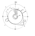
- the device comprises a DR drum consisting of a crown 1 with vertical axis arranged inside a metal outer casing or cage 2 of cylindrical shape for example.
- the cage has a first arm 3 and a second arm 4 to which are connected respectively a pipe 5 for supplying the gas streams to be purified, and a pipe 6 evacuation of these same flows after treatment.
- Crown 1 is provided with a interior partitioning consisting of a set of straight or curved blades 7 regularly distributed.
- a first angular sector A delimited by one or several blades, channels the flows from the conduit 5 to the central zone 8 of the cage (Fe flux in Fig. 3).
- a second angular sector B communicates the central zone 8 of the cage with the evacuation duct 6 (flow Fs in FIG. 3).
- the crown can also be arranged to serve as a support for a certain number of baskets.
- honeycomb structure such as that described in patent FR 2,564,037 of the applicant.
- the crown load can also consist of stones. In the case negative heat transfer. cryogenic nodules are used.
- Seals 9 are arranged between the cage and the crown to ensure vertical sealing and isolate the two spaces upstream and downstream from each other the central zone or transit zone 8, so that all the incoming flows are practically channeled towards it. These seals 9 are arranged so that the loss residual charge between crown 1 and cage 2, at least equal to the loss of load undergone by the gases in the exchange circuits.
- the circular configuration of the crown 1 and the cage 2, as well as the preferably curved shape of the vanes 7, are particularly well suited for withstand strong and frequent temperature variations. while ensuring a satisfactory guidance of flows passing through the device.
- the cage 2 and the crown 1. are driven by motor means (not shown) with a slow rotational movement relative to each other.
- the cage 2 also has at least one opening in its side wall in each of the angular sectors C. D intermediate between sectors A and B. where open conduits 10. 11 connected to suction means 13 (Fig.3).
- the peripheral gas leaks between the crown 1 and the cage 2 are sucked by the conduits 10, 11 (return flow Fr of FIG. 3) and reinjected into the conduit inlet 5 (incoming flow Fe).
- the cage 2 may also include openings into which one or more conduits 13 open (Fig. 1-2) to perform other functions. It may involve injecting an inhibitor chemical to avoid a parasitic chemical reaction such as polymerization, or well plugging. It can be a mechanical action: aspiration or blowing in order to clean the crown load. etc.
- cage 2 is fixed (Fig. 1) and crown 1 is driven in rotation.
- Fig. 2 it is the crown 1 which is fixed and the cage 2 driving with it the conduits 5. 6. which can rotate around its axis.
- a central zone 8 of the cage 2 In the central zone 8 of the cage 2, is disposed an intermediate cover 14 to selective openings.
- This cover 14 rotates at the same time as the cage 2 and is used to guide the incoming flow (Fe in Fig. 3) to the central zone 8 and the outgoing flow to a converging chamber 15 from which a discharge chimney 16 arranged to follow the rotation of the cage 2.
- the central zone 8 is used (Fig. 4) as a flow exchange zone for flow evacuation or admission.
- the operation is identical for a reverse heat transfer.
- the flow of cold gas admitted via line 5 cools the mass M in the sector angular A of the crown.
- Via line 18. a warmer gas flow is admitted who. by crossing the angular zone B. is then in contact with the particles which have been cooled during their passage in zone A and exit through line 6 at a lower temperature.
Landscapes
- Engineering & Computer Science (AREA)
- Environmental & Geological Engineering (AREA)
- Mechanical Engineering (AREA)
- General Engineering & Computer Science (AREA)
- Physics & Mathematics (AREA)
- Thermal Sciences (AREA)
- Exhaust Gas Treatment By Means Of Catalyst (AREA)
- Treating Waste Gases (AREA)
- Physical Or Chemical Processes And Apparatus (AREA)
- Chimneys And Flues (AREA)
- Incineration Of Waste (AREA)
- Devices And Processes Conducted In The Presence Of Fluids And Solid Particles (AREA)
- Heat-Exchange Devices With Radiators And Conduit Assemblies (AREA)
- Muffle Furnaces And Rotary Kilns (AREA)
Description
- la Fig. 1 montre une vue en coupe schématique d'un premier mode de réalisation du dispositif, avec une couronne tournante;
- la Fig.2 montre une vue schématique en coupe simplifiée d'un deuxième mode de réalisation du dispositif avec une cage susceptible de tourner autour de la couronne;
- la Fig.3 montre une vue éclatée du tambour tournant pour illustrer schématiquement les circulations des flux à l'intérieur du tambour rotatif; et
- la Fig.4 montre schématiquement un mode de réalisation de l'échange thermique dans la zone centrale.
Claims (9)
- Dispositif rotatif de transfert appliqué à des flux gazeux, comportant une enveloppe ou cage (2), une couronne (1) contenant une charge (M) de matériaux solides possédant une grande surface d'échange thermique, qui est disposée à l'intérieur de la cage, et des moyens moteurs pour animer la couronne et la cage d'un mouvement de rotation l'une relativement à l'autre autour d'un axe vertical, au moins un circuit primaire de circulation pour un premier flux comprenant un conduit (5) d'introduction dans la cage (2) et un deuxième conduit (17) d'évacuation disposé dans la zone centrale (8) de la cage (2), communiquant l'un avec l'autre au travers d'au moins une premier secteur (A) où s'effectue un premier transfert de chaleur entre le premier flux et la charge (M) dans la couronne (1), et un circuit secondaire de circulation pour un deuxième flux comprenant un conduit (18) dans la zone centrale (8) de la cage et au moins un conduit (6) d'évacuation hors de la cage, communiquant l'un avec l'autre au travers d'au moins un deuxième secteur (B) de la couronne (1) où s'effectue une deuxième transfert de chaleur entre le deuxième flux et la charge (M) dans la couronne, caractérisé en ce qu'il comporte des moyens (11,12) pour aspirer des flux de reprise dans au moins un secteur (C, D) de la couronne (1) intermédiaire entre le premier et le deuxième secteur de transfert thermique.
- Dispositif selon la revendication 1, caractérisé en ce qu'il comporte des moyens (13) pour faire communiquer l'intérieur de la couronne avec des moyens mécaniques ou aérauliques de nettoyage de la masse (M).
- Dispositif selon l'une des revendications 1 ou 2, caractérisé en ce qu'il comporte des moyens (13) pour faire communiquer l'intérieur de la couronne avec des moyens d'injection de substances chimiques.
- Dispositif selon l'une des revendications précédentes, caractérisé en ce que la couronne (1) est fixe, les moyens moteurs sont associés à la cage (2) qui est mobile relativement à la couronne (1), et les conduits (5, 6) d'amenée et d'évacuation sont fixés à la cage (2) et tournent avec elle.
- Dispositif selon l'une des revendications précédentes, caractérisé en ce que la masse (M) est constituée de nodules cryogéniques.
- Dispositif selon l'une des revendications précédentes, caractérisé en ce que la couronne (1) est divisée en plusieurs zones angulaires par un cloisonnement intérieur (7).
- Dispositif selon l'une des revendications précédentes, caractérisé en ce que la couronne (1) est agencée pour servir de support à plusieurs paniers contenant la charge (M).
- Dispositif selon l'une des revendications précédentes, caractérisé en ce que la charge (M1) de la couronne (1) comporte un garnissage en vrac constitué de billes ou de tournures ou copeaux d'usinage.
- Dispositif selon l'une des revendications précédentes, caractérisé en ce que la charge (M1) de la couronne (1) comporte une structure alvéolaire telle que du nid d'abeille ou du tricot métallique ou en céramique.
Applications Claiming Priority (2)
| Application Number | Priority Date | Filing Date | Title |
|---|---|---|---|
| FR9406282A FR2720488B1 (fr) | 1994-05-24 | 1994-05-24 | Dispositif rotatif de transfert de chaleur et d'épuration thermique appliqué à des effluents gazeux. |
| FR9406282 | 1994-05-24 |
Publications (2)
| Publication Number | Publication Date |
|---|---|
| EP0684427A1 EP0684427A1 (fr) | 1995-11-29 |
| EP0684427B1 true EP0684427B1 (fr) | 2001-02-28 |
Family
ID=9463462
Family Applications (1)
| Application Number | Title | Priority Date | Filing Date |
|---|---|---|---|
| EP95401154A Expired - Lifetime EP0684427B1 (fr) | 1994-05-24 | 1995-05-18 | Dispositif rotatif de transfert de chaleur |
Country Status (9)
| Country | Link |
|---|---|
| US (1) | US5643538A (fr) |
| EP (1) | EP0684427B1 (fr) |
| JP (1) | JP3655667B2 (fr) |
| KR (1) | KR100414430B1 (fr) |
| CA (1) | CA2150000C (fr) |
| DE (1) | DE69520168T2 (fr) |
| ES (1) | ES2156597T3 (fr) |
| FR (1) | FR2720488B1 (fr) |
| NO (1) | NO304906B1 (fr) |
Families Citing this family (17)
| Publication number | Priority date | Publication date | Assignee | Title |
|---|---|---|---|---|
| FR2728483B1 (fr) * | 1994-12-26 | 1997-01-24 | Inst Francais Du Petrole | Dispositif rotatif perfectionne d'epuration catalytique d'effluents pollues |
| US5972299A (en) * | 1996-09-26 | 1999-10-26 | Industrial Technology Research Institute | Catalytic converter with heating for motorcycles |
| FR2756753B1 (fr) * | 1996-12-05 | 1998-12-31 | Inst Francais Du Petrole | Dispositif rotatif perfectionne d'epuration catalytique d'effluents gazeux |
| US6193504B1 (en) | 1997-04-01 | 2001-02-27 | Engelhard Corporation | Portable rotary catalytic oxidizer systems |
| US6235249B1 (en) | 1997-04-01 | 2001-05-22 | Engelhard Corporation | Rotary oxidizer systems for control of restaurant emissions |
| US6261524B1 (en) | 1999-01-12 | 2001-07-17 | Advanced Technology Materials, Inc. | Advanced apparatus for abatement of gaseous pollutants |
| US6153150A (en) * | 1998-01-12 | 2000-11-28 | Advanced Technology Materials, Inc. | Apparatus and method for controlled decomposition oxidation of gaseous pollutants |
| CN1311844A (zh) * | 1998-07-31 | 2001-09-05 | 大众汽车有限公司 | 用于内燃机的发动机废气后处理的设备和方法 |
| FR2786551B1 (fr) * | 1998-11-26 | 2000-12-29 | Inst Francais Du Petrole | Dispositif de raccordement tournant etanche autorisant des debattements importants |
| DE10324937A1 (de) * | 2003-06-03 | 2004-12-23 | Deere & Company, Moline | Vorrichtung zum Wärmeaustausch |
| GB2433041A (en) * | 2005-12-08 | 2007-06-13 | Eminox Ltd | Cleaning a vehicle exhaust system filter |
| DE102006034483A1 (de) * | 2006-07-21 | 2008-01-24 | Alstom Technology Ltd. | Regenerativer Luftvorwärmer mit Bürstendichtung |
| DE502007007132D1 (de) * | 2007-07-24 | 2011-06-16 | Balcke Duerr Gmbh | Regenerativ-Wärmeaustauscher und Radialdichtung zur Verwendung für einen solchen sowie Verfahren zum Trennen von gasförmigen Medien in einem regenerativ-Wärmeaustauscher |
| DE102008022188B4 (de) * | 2008-05-05 | 2010-02-11 | Applikations- Und Technikzentrum Für Energieverfahrens-, Umwelt- Und Strömungstechnik (Atz-Evus) | Verfahren zum Betreiben einer Dampfturbine |
| FR2961893B1 (fr) * | 2010-06-25 | 2014-12-12 | Air Liquide | Echangeur de chaleur regeneratif rotatif |
| GB2574065B (en) * | 2018-05-25 | 2021-06-16 | Intelligent Power Generation Ltd | Rotary regenerator |
| CN121140054A (zh) * | 2025-11-19 | 2025-12-16 | 山西中能远大机电设备科技股份有限公司 | 一种矿井的采暖通风设备 |
Family Cites Families (14)
| Publication number | Priority date | Publication date | Assignee | Title |
|---|---|---|---|---|
| FR1397214A (fr) * | 1964-01-02 | 1965-04-30 | Chausson Usines Sa | Echangeur de chaleur rotatif |
| US3404965A (en) * | 1964-11-13 | 1968-10-08 | Benjamin P. Shiller | Fume combustion apparatus |
| GB1166209A (en) * | 1968-06-26 | 1969-10-08 | Kazakhsk Nii Energetiki | Apparatus for Carrying out Chemical Reactions in a Current of Gas Reagents and especially suitable for Burning out Combustible Components from a Gas Mixture of Low Calorific Value |
| US3678992A (en) * | 1970-08-06 | 1972-07-25 | Philips Corp | Thermal regenerator |
| US3870474B1 (en) * | 1972-11-13 | 1991-04-02 | Regenerative incinerator systems for waste gases | |
| FR2373769A1 (fr) * | 1976-12-07 | 1978-07-07 | Air Ind | Perfectionnements apportes aux echangeurs de chaleur dynamiques |
| US4231418A (en) * | 1979-05-07 | 1980-11-04 | Hughes Aircraft Company | Cryogenic regenerator |
| DE2951279A1 (de) * | 1979-12-20 | 1981-07-16 | L. & C. Steinmüller GmbH, 5270 Gummersbach | Regenerativer waermeaustauscher |
| FR2564037B1 (fr) | 1984-05-11 | 1986-10-03 | Inst Francais Du Petrole | Structure alveolaire destinee a recouvrir une surface curviligne et procede de realisation |
| DE3516831A1 (de) * | 1985-05-10 | 1986-11-13 | Ferdinand Lentjes, Dampfkessel- und Maschinenbau, 4000 Düsseldorf | Verfahren und vorrichtung zum betreiben eines regenerativ-gasvorwaermers |
| JPS62266120A (ja) * | 1986-05-12 | 1987-11-18 | Asahi Glass Co Ltd | 塗装乾燥炉の排ガス処理装置 |
| DE3805791A1 (de) * | 1988-02-24 | 1989-08-31 | Kraftanlagen Ag | Verfahren und anlage zur entstickung der abgase von feuerungsanlagen |
| US5362449A (en) * | 1991-02-26 | 1994-11-08 | Applied Regenerative Tech. Co., Inc. | Regenerative gas treatment |
| WO1994023246A1 (fr) * | 1993-03-26 | 1994-10-13 | Applied Regenerative Technologies Co., Inc. | Traitement regenerateur de gaz |
-
1994
- 1994-05-24 FR FR9406282A patent/FR2720488B1/fr not_active Expired - Fee Related
-
1995
- 1995-05-18 EP EP95401154A patent/EP0684427B1/fr not_active Expired - Lifetime
- 1995-05-18 ES ES95401154T patent/ES2156597T3/es not_active Expired - Lifetime
- 1995-05-18 DE DE69520168T patent/DE69520168T2/de not_active Expired - Lifetime
- 1995-05-22 US US08/445,958 patent/US5643538A/en not_active Expired - Lifetime
- 1995-05-22 NO NO952023A patent/NO304906B1/no not_active IP Right Cessation
- 1995-05-23 CA CA002150000A patent/CA2150000C/fr not_active Expired - Fee Related
- 1995-05-24 KR KR1019950012992A patent/KR100414430B1/ko not_active Expired - Fee Related
- 1995-05-24 JP JP14960395A patent/JP3655667B2/ja not_active Expired - Fee Related
Also Published As
| Publication number | Publication date |
|---|---|
| FR2720488B1 (fr) | 1996-07-12 |
| US5643538A (en) | 1997-07-01 |
| NO304906B1 (no) | 1999-03-01 |
| NO952023D0 (no) | 1995-05-22 |
| FR2720488A1 (fr) | 1995-12-01 |
| CA2150000A1 (fr) | 1995-11-25 |
| KR100414430B1 (ko) | 2004-03-09 |
| EP0684427A1 (fr) | 1995-11-29 |
| KR950033399A (ko) | 1995-12-26 |
| JP3655667B2 (ja) | 2005-06-02 |
| ES2156597T3 (es) | 2001-07-01 |
| CA2150000C (fr) | 2006-02-14 |
| DE69520168T2 (de) | 2001-06-21 |
| NO952023L (no) | 1995-11-27 |
| DE69520168D1 (de) | 2001-04-05 |
| JPH0868596A (ja) | 1996-03-12 |
Similar Documents
| Publication | Publication Date | Title |
|---|---|---|
| CA2150000C (fr) | Dispositif rotatif de transfert de chaleur et d'epuration thermique applique a des effluents gazeux | |
| EP0757585B1 (fr) | Dispositif rotatif d'epuration catalytique d'effluents gazeux pollues | |
| LU85573A1 (fr) | Dispositif du type prechauffeur d'air pour le prechauffage de l'air de combustion dans un procede de combustion,avec reduction simultanee du nox contenu dans les gaz brueles | |
| FR2858652A1 (fr) | Dispositif de controle de jeu dans une turbine a gaz | |
| EP1794526B1 (fr) | Régéneration par calcination d'oxydants thermiques pendant le fonctionnement normal | |
| WO1999019682A1 (fr) | Dispositif d'oxydation thermique a robinet a tournant | |
| JP3798360B2 (ja) | 分離組立型の風向転換装置を有する四角形の蓄熱式燃焼装置、及びその風向転換方法 | |
| MC986A1 (fr) | Installation pour chauffer ou vaporiser des liquides ou des gaz | |
| JP4431490B2 (ja) | 弁及び弁を備えた再生式熱酸化装置用の高温シールエア | |
| JP4529230B2 (ja) | ロータリーキルン | |
| KR100196029B1 (ko) | 연소장치용 열교환기 | |
| CN213021033U (zh) | 一种合金烧结炉用余热回收装置 | |
| CN107191628A (zh) | 一种用于旋转式蓄热氧化炉的换向阀 | |
| CN106439865A (zh) | 一种连续蓄热式voc有机废气焚烧炉 | |
| CN111704337A (zh) | 一种工业污泥等处理用于碳化、热解装置 | |
| EP0846492B1 (fr) | Procédé d'épuration catalytique d'effluents gazeux | |
| KR100954736B1 (ko) | 상부 연소장치와 직결되고 열팽창에 의한 간극 변형량을 흡수할 수 있는 분리조립형 로터리 밸브를 구비한 축열식연소장치 | |
| RU2123154C1 (ru) | Вращающийся регенеративный воздухоподогреватель | |
| EP0774572B1 (fr) | Turbine à gaz compacte à cycle fermé pour la propulsion d'un véhicule | |
| CN212081305U (zh) | 一种径向流回转蓄热式空气预热器 | |
| FR2863311A1 (fr) | Ensemble de turbine isole de facon interne pour un moteur a turbine a combustion | |
| CN224051058U (zh) | 一种尾气脱硫脱硝余热回收装置 | |
| BE570543A (fr) | ||
| EP0113602A1 (fr) | Dispositif d'absorption du rayonnement solaire concentré et procédé de réalisation d'un tel dispositif | |
| FR2720294A1 (fr) | Dispositif rotatif de concentration et d'épuration d'effluents gazeux contenant des composés organiques voltatils (COV). |
Legal Events
| Date | Code | Title | Description |
|---|---|---|---|
| PUAI | Public reference made under article 153(3) epc to a published international application that has entered the european phase |
Free format text: ORIGINAL CODE: 0009012 |
|
| AK | Designated contracting states |
Kind code of ref document: A1 Designated state(s): BE DE ES GB IT NL SE |
|
| 17P | Request for examination filed |
Effective date: 19960529 |
|
| 17Q | First examination report despatched |
Effective date: 19971125 |
|
| GRAG | Despatch of communication of intention to grant |
Free format text: ORIGINAL CODE: EPIDOS AGRA |
|
| RTI1 | Title (correction) |
Free format text: ROTATING HEAT TRANSFER DEVICE |
|
| GRAG | Despatch of communication of intention to grant |
Free format text: ORIGINAL CODE: EPIDOS AGRA |
|
| GRAH | Despatch of communication of intention to grant a patent |
Free format text: ORIGINAL CODE: EPIDOS IGRA |
|
| RTI1 | Title (correction) |
Free format text: ROTATING HEAT TRANSFER DEVICE |
|
| ITF | It: translation for a ep patent filed | ||
| GRAH | Despatch of communication of intention to grant a patent |
Free format text: ORIGINAL CODE: EPIDOS IGRA |
|
| GRAA | (expected) grant |
Free format text: ORIGINAL CODE: 0009210 |
|
| AK | Designated contracting states |
Kind code of ref document: B1 Designated state(s): BE DE ES GB IT NL SE |
|
| GBT | Gb: translation of ep patent filed (gb section 77(6)(a)/1977) |
Effective date: 20010228 |
|
| REF | Corresponds to: |
Ref document number: 69520168 Country of ref document: DE Date of ref document: 20010405 |
|
| REG | Reference to a national code |
Ref country code: ES Ref legal event code: FG2A Ref document number: 2156597 Country of ref document: ES Kind code of ref document: T3 |
|
| REG | Reference to a national code |
Ref country code: GB Ref legal event code: IF02 |
|
| PLBE | No opposition filed within time limit |
Free format text: ORIGINAL CODE: 0009261 |
|
| STAA | Information on the status of an ep patent application or granted ep patent |
Free format text: STATUS: NO OPPOSITION FILED WITHIN TIME LIMIT |
|
| 26N | No opposition filed | ||
| PGFP | Annual fee paid to national office [announced via postgrant information from national office to epo] |
Ref country code: GB Payment date: 20100324 Year of fee payment: 16 |
|
| PGFP | Annual fee paid to national office [announced via postgrant information from national office to epo] |
Ref country code: ES Payment date: 20100518 Year of fee payment: 16 |
|
| PGFP | Annual fee paid to national office [announced via postgrant information from national office to epo] |
Ref country code: NL Payment date: 20100526 Year of fee payment: 16 Ref country code: IT Payment date: 20100519 Year of fee payment: 16 Ref country code: DE Payment date: 20100602 Year of fee payment: 16 |
|
| PGFP | Annual fee paid to national office [announced via postgrant information from national office to epo] |
Ref country code: BE Payment date: 20100526 Year of fee payment: 16 |
|
| PGFP | Annual fee paid to national office [announced via postgrant information from national office to epo] |
Ref country code: SE Payment date: 20100520 Year of fee payment: 16 |
|
| REG | Reference to a national code |
Ref country code: DE Ref legal event code: R081 Ref document number: 69520168 Country of ref document: DE Owner name: IFP ENERGIES NOUVELLES, FR Free format text: FORMER OWNERS: INSTITUT FRANCAIS DU PETROLE, RUEIL-MALMAISON, HAUTS-DE-SEINE, FR; BOURCIER, JACQUES, SAINT-NAZAIRE, FR Effective date: 20110329 Ref country code: DE Ref legal event code: R081 Ref document number: 69520168 Country of ref document: DE Owner name: BOURCIER, JACQUES, FR Free format text: FORMER OWNERS: INSTITUT FRANCAIS DU PETROLE, RUEIL-MALMAISON, HAUTS-DE-SEINE, FR; BOURCIER, JACQUES, SAINT-NAZAIRE, FR Effective date: 20110329 Ref country code: DE Ref legal event code: R081 Ref document number: 69520168 Country of ref document: DE Owner name: IFP ENERGIES NOUVELLES, FR Free format text: FORMER OWNER: INSTITUT FRANCAIS DU PETROLE,JACQUES BOURCIER, , FR Effective date: 20110329 Ref country code: DE Ref legal event code: R081 Ref document number: 69520168 Country of ref document: DE Owner name: BOURCIER, JACQUES, FR Free format text: FORMER OWNER: INSTITUT FRANCAIS DU PETROLE,JACQUES BOURCIER, , FR Effective date: 20110329 |
|
| BERE | Be: lapsed |
Owner name: *BOURCIER JACQUES Effective date: 20110531 Owner name: INSTITUT FRANCAIS DU *PETROLE Effective date: 20110531 |
|
| REG | Reference to a national code |
Ref country code: DE Ref legal event code: R119 Ref document number: 69520168 Country of ref document: DE |
|
| REG | Reference to a national code |
Ref country code: DE Ref legal event code: R119 Ref document number: 69520168 Country of ref document: DE |
|
| REG | Reference to a national code |
Ref country code: NL Ref legal event code: V1 Effective date: 20111201 |
|
| REG | Reference to a national code |
Ref country code: SE Ref legal event code: EUG |
|
| GBPC | Gb: european patent ceased through non-payment of renewal fee |
Effective date: 20110518 |
|
| PG25 | Lapsed in a contracting state [announced via postgrant information from national office to epo] |
Ref country code: NL Free format text: LAPSE BECAUSE OF NON-PAYMENT OF DUE FEES Effective date: 20111201 |
|
| PG25 | Lapsed in a contracting state [announced via postgrant information from national office to epo] |
Ref country code: IT Free format text: LAPSE BECAUSE OF NON-PAYMENT OF DUE FEES Effective date: 20110518 |
|
| PG25 | Lapsed in a contracting state [announced via postgrant information from national office to epo] |
Ref country code: BE Free format text: LAPSE BECAUSE OF NON-PAYMENT OF DUE FEES Effective date: 20110531 |
|
| PG25 | Lapsed in a contracting state [announced via postgrant information from national office to epo] |
Ref country code: GB Free format text: LAPSE BECAUSE OF NON-PAYMENT OF DUE FEES Effective date: 20110518 |
|
| PG25 | Lapsed in a contracting state [announced via postgrant information from national office to epo] |
Ref country code: SE Free format text: LAPSE BECAUSE OF NON-PAYMENT OF DUE FEES Effective date: 20110519 |
|
| PG25 | Lapsed in a contracting state [announced via postgrant information from national office to epo] |
Ref country code: DE Free format text: LAPSE BECAUSE OF NON-PAYMENT OF DUE FEES Effective date: 20111130 |
|
| REG | Reference to a national code |
Ref country code: ES Ref legal event code: FD2A Effective date: 20130702 |
|
| PG25 | Lapsed in a contracting state [announced via postgrant information from national office to epo] |
Ref country code: ES Free format text: LAPSE BECAUSE OF NON-PAYMENT OF DUE FEES Effective date: 20110519 |