EP0684493A2 - Bauelemente für optisches Wellenlängenmultiplex - Google Patents
Bauelemente für optisches Wellenlängenmultiplex Download PDFInfo
- Publication number
- EP0684493A2 EP0684493A2 EP95302819A EP95302819A EP0684493A2 EP 0684493 A2 EP0684493 A2 EP 0684493A2 EP 95302819 A EP95302819 A EP 95302819A EP 95302819 A EP95302819 A EP 95302819A EP 0684493 A2 EP0684493 A2 EP 0684493A2
- Authority
- EP
- European Patent Office
- Prior art keywords
- optical
- waveguide
- output
- waveguides
- filtering elements
- Prior art date
- Legal status (The legal status is an assumption and is not a legal conclusion. Google has not performed a legal analysis and makes no representation as to the accuracy of the status listed.)
- Withdrawn
Links
- 230000003287 optical effect Effects 0.000 title claims abstract description 133
- 238000001914 filtration Methods 0.000 claims abstract description 61
- 230000005540 biological transmission Effects 0.000 claims abstract description 36
- 239000013307 optical fiber Substances 0.000 claims abstract description 12
- 239000000835 fiber Substances 0.000 claims description 28
- 230000010287 polarization Effects 0.000 claims description 11
- 238000005253 cladding Methods 0.000 claims description 4
- 230000035945 sensitivity Effects 0.000 claims description 4
- 239000012792 core layer Substances 0.000 claims 2
- 230000003595 spectral effect Effects 0.000 abstract description 10
- 238000000034 method Methods 0.000 abstract description 9
- 238000003491 array Methods 0.000 abstract description 3
- 230000005855 radiation Effects 0.000 description 33
- 238000000411 transmission spectrum Methods 0.000 description 5
- 230000000903 blocking effect Effects 0.000 description 4
- 238000004891 communication Methods 0.000 description 4
- 238000004519 manufacturing process Methods 0.000 description 4
- UFHFLCQGNIYNRP-UHFFFAOYSA-N Hydrogen Chemical compound [H][H] UFHFLCQGNIYNRP-UHFFFAOYSA-N 0.000 description 3
- 230000008878 coupling Effects 0.000 description 3
- 238000010168 coupling process Methods 0.000 description 3
- 238000005859 coupling reaction Methods 0.000 description 3
- 238000012986 modification Methods 0.000 description 3
- 230000004048 modification Effects 0.000 description 3
- 230000015572 biosynthetic process Effects 0.000 description 2
- 150000001875 compounds Chemical class 0.000 description 2
- 238000013461 design Methods 0.000 description 2
- 239000001257 hydrogen Substances 0.000 description 2
- 229910052739 hydrogen Inorganic materials 0.000 description 2
- 238000005984 hydrogenation reaction Methods 0.000 description 2
- 238000000059 patterning Methods 0.000 description 2
- 238000001228 spectrum Methods 0.000 description 2
- VYZAMTAEIAYCRO-UHFFFAOYSA-N Chromium Chemical compound [Cr] VYZAMTAEIAYCRO-UHFFFAOYSA-N 0.000 description 1
- VYPSYNLAJGMNEJ-UHFFFAOYSA-N Silicium dioxide Chemical compound O=[Si]=O VYPSYNLAJGMNEJ-UHFFFAOYSA-N 0.000 description 1
- 229910052804 chromium Inorganic materials 0.000 description 1
- 239000011651 chromium Substances 0.000 description 1
- 239000002131 composite material Substances 0.000 description 1
- 238000001816 cooling Methods 0.000 description 1
- 230000000694 effects Effects 0.000 description 1
- 238000000609 electron-beam lithography Methods 0.000 description 1
- 238000005516 engineering process Methods 0.000 description 1
- 239000005350 fused silica glass Substances 0.000 description 1
- 238000007526 fusion splicing Methods 0.000 description 1
- 229910052732 germanium Inorganic materials 0.000 description 1
- GNPVGFCGXDBREM-UHFFFAOYSA-N germanium atom Chemical compound [Ge] GNPVGFCGXDBREM-UHFFFAOYSA-N 0.000 description 1
- 239000011521 glass Substances 0.000 description 1
- 238000010438 heat treatment Methods 0.000 description 1
- 238000010348 incorporation Methods 0.000 description 1
- 238000001459 lithography Methods 0.000 description 1
- 230000010363 phase shift Effects 0.000 description 1
- 238000001020 plasma etching Methods 0.000 description 1
- 230000002269 spontaneous effect Effects 0.000 description 1
- 239000000758 substrate Substances 0.000 description 1
Images

Classifications
-
- G—PHYSICS
- G02—OPTICS
- G02B—OPTICAL ELEMENTS, SYSTEMS OR APPARATUS
- G02B6/00—Light guides; Structural details of arrangements comprising light guides and other optical elements, e.g. couplings
- G02B6/24—Coupling light guides
- G02B6/26—Optical coupling means
- G02B6/28—Optical coupling means having data bus means, i.e. plural waveguides interconnected and providing an inherently bidirectional system by mixing and splitting signals
- G02B6/293—Optical coupling means having data bus means, i.e. plural waveguides interconnected and providing an inherently bidirectional system by mixing and splitting signals with wavelength selective means
- G02B6/29304—Optical coupling means having data bus means, i.e. plural waveguides interconnected and providing an inherently bidirectional system by mixing and splitting signals with wavelength selective means operating by diffraction, e.g. grating
- G02B6/29316—Light guides comprising a diffractive element, e.g. grating in or on the light guide such that diffracted light is confined in the light guide
- G02B6/29317—Light guides of the optical fibre type
- G02B6/29319—With a cascade of diffractive elements or of diffraction operations
-
- G—PHYSICS
- G02—OPTICS
- G02B—OPTICAL ELEMENTS, SYSTEMS OR APPARATUS
- G02B6/00—Light guides; Structural details of arrangements comprising light guides and other optical elements, e.g. couplings
- G02B6/24—Coupling light guides
- G02B6/26—Optical coupling means
- G02B6/28—Optical coupling means having data bus means, i.e. plural waveguides interconnected and providing an inherently bidirectional system by mixing and splitting signals
- G02B6/293—Optical coupling means having data bus means, i.e. plural waveguides interconnected and providing an inherently bidirectional system by mixing and splitting signals with wavelength selective means
- G02B6/29379—Optical coupling means having data bus means, i.e. plural waveguides interconnected and providing an inherently bidirectional system by mixing and splitting signals with wavelength selective means characterised by the function or use of the complete device
- G02B6/2938—Optical coupling means having data bus means, i.e. plural waveguides interconnected and providing an inherently bidirectional system by mixing and splitting signals with wavelength selective means characterised by the function or use of the complete device for multiplexing or demultiplexing, i.e. combining or separating wavelengths, e.g. 1xN, NxM
-
- H—ELECTRICITY
- H04—ELECTRIC COMMUNICATION TECHNIQUE
- H04J—MULTIPLEX COMMUNICATION
- H04J14/00—Optical multiplex systems
- H04J14/02—Wavelength-division multiplex systems
- H04J14/03—WDM arrangements
- H04J14/0307—Multiplexers; Demultiplexers
Definitions
- the invention relates to wavelength division optical multiplexing and, more particularly, to wavelength division demultiplexers and multiplexers including arrays of optical filtering elements such as Bragg gratings, that form optical filters having characteristic wavelength passbands.
- Wavelength-division multiplexing is a valuable technique for increasing the information-carrying capacity of an optical communication network.
- it is essential to provide wavelength-selective components that can separate a particular wavelength channel from a group of multiplexed channels.
- Bragg gratings elements comprising regions of refractive index perturbations which reflect particular wavelengths, are advantageously used to provide spectral selectivity. They are readily made with passbands that match desired channel widths, and they are readily integrated with optical waveguides such as optical fibers, planar, and channel waveguides.
- Current channel-selective filters using Bragg gratings can suffer from relatively high coupling losses; others are difficult to manufacture because they must be made to extremely close tolerances.
- one known filter configuration includes an input fiber coupled to a fiber-based Bragg grating through a directional optical coupler. Light reflected from the grating is coupled to an output waveguide through the same coupler. In this manner, the narrow reflection band of the grating is effectively transformed into a transmission band for the filter as a whole.
- this arrangement suffers 6 dB of coupling loss, to which is added the intrinsic loss in the directional coupler.
- This filter consists of a loop of single-mode optical fiber which includes a fused-taper directional coupler at the point where the loop branches off from the straight part of the fiber.
- a Bragg grating is situated symmetrically midway in the fiber loop.
- This filter can be made to have relatively low loss.
- this filter is difficult to manufacture because exact placement of the Bragg grating is required in order to achieve the desired transmission characteristics.
- Bilodeau et al. "High-Return-Loss Narrowbond All-Fiber Bandpass Bragg Transmission Filter," IBEE Photonics Technology Letters , Vol. 6, No. 1, (1994), pp. 80-82 describes a design modification of the Hill et al. filter.
- a filter having desirable spectral properties can be made by forming a Bragg grating having many, e.g., 15, sections, each with a different spatial period. To avoid phase shifts near 90° between sections, the sections are made contiguous, resulting in a grating period that is piecewise constant, but discontinuously varied.
- wavelength division multiplexing elements which are simple to manufacture and which are readily formed from optical filtering elements which separate a particular wavelength channel from a group of multiplexed channels.
- wavelength division optical multiplexing elements which are insensitive to the polarization of incident radiation.
- the present invention relates to methods and apparatus for wavelength division multiplexing (WDM) using arrays of optical filtering elements to create a desired wavelength passband in an optical filter.
- WDM wavelength division multiplexing
- an optical demultiplexer is formed using an input waveguide, such as a planar waveguide or an optical fiber, coupled to plural output waveguides.
- Each output waveguide includes a wavelength selective configuration of optical filtering elements formed within a contiguous portion of the waveguide.
- the configuration forms an optical channel-selective filter with spectral regions having an optical transmission passband and spectral regions of low transmissivity.
- the invention relates to an optical demultiplexer having an input waveguide and N output waveguides, N being a whole number greater than or equal to 2.
- Each output waveguide includes a wavelength-selective configuration of at least (N-1) optical filtering elements such as Bragg gratings, each of the Bragg gratings having at least one wavelength band of low transmissivity, ⁇ x where each x is a number from 1 to N.
- the configuration of optical filtering elements creates an optical filter which transmits a characteristic wavelength band, i.e., the wavelength band ⁇ n of the Bragg grating absent from the configuration of optical filtering elements in the waveguide.
- a connecting element such as a 1xN coupler is positioned between the input and output waveguides to divide optical transmissions from the input waveguide among the output waveguides.
- the present invention provides an optical demultiplexer having an input waveguide and N output waveguides.
- Y branching waveguides are positioned between the input waveguide and the output waveguides, Y being a whole number greater than or equal to 2 and less than or equal to N-1.
- each of the output waveguides transmits a characteristic wavelength band, ⁇ n , where n is a whole number from 1 to N.
- Positioned within the output waveguides and said branching waveguides are a plurality of optical filtering elements each optical filtering element having a different wavelength band of low transmissivity ⁇ x , where x is a whole number from 1 to N and is not equal to n, the number corresponding to the channel passband.
- the plurality of optical filtering elements is configured such that within the optical path of the transmission emitted from each output waveguide are positioned at least N-1 optical filtering elements, each of the N-1 optical filtering elements having a different wavelength band of low transmissivity.
- the combination of the optical filtering elements is such that the combination of the low transmissivity wavelength bands of each of the N-1 optical filtering elements results in transmission of the characteristic wavelength, ⁇ n .
- the branching waveguide includes all of the optical filtering elements for the wavelength bands which are not to be transmitted by any of the output waveguides connected to that branching waveguide.
- the present invention relates to polarization-insensitive wavelength division demultiplexers.
- the demultiplexer includes an input optical waveguide and plural output waveguides. Each output waveguide has a plurality of optical filtering elements integrally formed within a contiguous portion of the waveguide.
- the demultiplexers exhibit a polarization sensitivity of about 1 part in 100,000 or less.
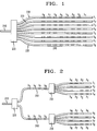
- FIG. 1 is a schematic representation of an 8-channel optical demultiplexer according to one embodiment of the present invention.
- FIG. 2 is a schematic representation of an 8-channel optical demultiplexer according to a further embodiment of the present invention.
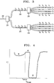
- FIG. 3 is a schematic representation of an 8-channel demultiplexer according to a further embodiment of the present invention.
- FIG. 4 is a transmission spectrum of a Bragg grating used as an optical filtering element according to the invention in one embodiment.
- FIG. 5 is a transmission spectrum for one channel of the demultiplexer of FIG. 1.
- demultiplexer or “demultiplexing” as used herein encompasses any device used to separate a particular wavelength band from a group of multiplexed wavelength bands. This additionally includes devices used to route wavelength bands positioned well before the receivers in a transmission system.
- the demultiplexer includes an input optical waveguide and a plurality of output optical waveguides, each output optical waveguide having an optical filter comprising an array of optical filtering elements, such as Bragg diffraction gratings, formed in a contiguous portion of the output waveguide.
- demultiplexer 220 includes an input waveguide 210 and N output waveguides 220 coupled to waveguide 210 through 1 X N coupler 230.
- N 8; however N is any whole number greater than or equal to 2.
- Each output waveguide transmits a characteristic wavelength band, ⁇ n , where n is a whole number between 1 and N.
- n 8.
- the wavelength indices which appear at the terminus of each waveguide denote which desired signal wavelength band is passed by that output waveguide. It will be appreciated by those skilled in the art that radiation outside the signal wavelength bands may also be passed to the output waveguides; such radiation does not deleteriously impact system performance.
- Exemplary optical filtering elements 240 are Bragg gratings, each Bragg grating having a wavelength band of low transmissivity, i.e., the wavelength band which the grating attenuates. The combination of the optical filtering elements forms an optical filter in which all of the wavelength bands are blocked except the characteristic wavelength band of the output waveguide.
- the seven Bragg gratings positioned within that waveguide collectively attenuate wavelength bands ⁇ 2, ⁇ 3, ⁇ 4, ⁇ 5, ⁇ 6, ⁇ 7, and ⁇ 8, as illustrated in FIG. 1.
- the wavelength numbers which appear adjacent each grating in the output waveguides indicate the wavelength band blocked by that grating.
- an additional Bragg grating is positioned in the array.
- the additional Bragg grating does not correspond to a channel, but instead is used to broaden the channel of the Bragg grating with the shortest wavelength.
- a further Bragg grating can also be used to broaden the channel of the Bragg grating with the longest wavelength.
- the use of an additional Bragg grating on the short and/or long wavelength end of the spectrum permits attenuation of additional undesirable wavelengths, such as those which might result from amplified spontaneous emission noise in an optical amplifier.
- Each of the remaining output waveguides includes a similar array of filters, i.e., for the 8-channel demultiplexer of FIG. 1, there are seven Bragg gratings in each output waveguide, each Bragg grating blocking a different wavelength band between ⁇ 1 and ⁇ 8.
- ⁇ x to represent the characteristic wavelength band of the output waveguide
- the demultiplexer of FIG. 1 employs a Bragg grating for each channel to be blocked, a single Bragg grating can be used to block two or more channels simultaneously when the reflection peak of the grating is sufficiently wide.
- the demultiplexer has N channels but fewer than (N-1) optical filtering elements positioned within each output waveguide.
- FIG. 2 illustrates a further embodiment of a demultiplexer according to the present invention.
- branching waveguides 260 are positioned between the input waveguide 210 and N output waveguides 220.
- These branching waveguides have optical filtering elements 270, such as Bragg gratings, formed therein.
- the optical filtering elements formed within the branching waveguides eliminate the need to repeat the branching waveguide filtering elements within the output waveguides.
- the wavelength bands which are to be blocked by all output waveguide within a set of output waveguides have the corresponding optical filtering elements formed within the branching waveguide, eliminating the need to duplicate filtering element formation within each of the output waveguides.
- the input waveguide 210 is connected to the branching waveguides 260 through 1 x Y coupler 230, as in the previous embodiment, where Y is the number of branching waveguides which connect to the input waveguide. In general, Y is a whole number greater than or equal to 2 and less than or equal to N-1. In the demultiplexer of FIG. 2, N is equal to eight and Y is equal to two.
- a coupler 250 is positioned between branching waveguides 260 and output waveguides 220. In FIG. 2, 1 x 4 couplers are used to connect the branching and output waveguides.
- the branching waveguide which transmits radiation into these four output waveguides includes filtering elements which block the transmission of wavelength bands ⁇ 5- ⁇ 8.
- twenty-four fewer optical filtering elements are included in the output waveguides due to the addition of the branching waveguides having filtering elements blocking wavelength bands common to the connecting output waveguides.
- FIG. 3 An exemplary optical filtering element array for the branching configuration depicted in FIG. 2 is illustrated in FIG. 3.
- the selection of optical filtering elements is staggered such that the array of optical filtering elements in the output waveguides does not include optical filtering elements which block wavelength bands adjacent to the pass wavelength band of the output waveguide.
- the wavelength passband for the four output waveguides which connect to the first branching waveguide are selected to be ⁇ 1, ⁇ 3, ⁇ 5, and ⁇ 7.
- none of the output waveguides connected to the first branching waveguide will transmit wavelength bands ⁇ 2, ⁇ 4, ⁇ 6, and ⁇ 8. For this reason, filtering elements which block the transmission of ⁇ 2, ⁇ 4, ⁇ 6, and ⁇ 8 are positioned within the first branching waveguide.
- the remaining wavelength bands to be blocked in order to transmit the desired wavelength band are positioned in the output waveguide.
- the remaining wavelength bands to be blocked are ⁇ 3, ⁇ 5, and ⁇ 7.
- Filtering elements such as Bragg gratings which block these wavelength bands are positioned within the output waveguide as shown in FIG. 3. This configuration of filtering elements advantageously permits relaxed tolerances on grating positioning in the output waveguides since twice the channel spacing is produced in the output waveguides through the blocking of alternate wavelength bands by the gratings positioned in the branching waveguides.
- region 20 is a wavelength band having a transmission minimum which corresponds to incident radiation reflected or scattered by the grating.
- dip 30 On the short wavelength side of transmission minimum 20 is dip 30. Dip 30 results from radiation loss and is separated from transmission minimum 20 by relatively high transmissivity region 40.
- radiation loss describes any light which is scattered out of the core of the waveguide, including radiation scattered in the cladding of the waveguide.
- the short-wavelength edge of transmission minimum 20 is ⁇ Bragg , i.e., the Bragg wavelength in the limit of a very weak grating.
- gratings may be formed in waveguiding media having weak radiation loss and fused to transmission waveguiding media. Peak radiation loss can further be reduced by recoating the grating region of the waveguide to improve transmission characteristics. See, for example, Mizrahi and Sipe, J. of Light Tech. , Vol. 11 (October 1993) pp. 1513-1517, especially Figs. 3(a) and 4,
- the design of the optical filter also minimizes or reduces the effects of radiation loss.
- the grating configuration positions channel passbands in spectral regions where there is no radiation loss region from other gratings in the filter.
- weaker gratings are formed by controlling the amount of actinic radiation exposure, and hydrogenation level and germanium doping levels in hydrogen-treated germanosilicate waveguides.
- the waveguides employed in the demultiplexers of FIGS. 1-3 are exemplarily single-mode optical fibers, as are typically employed in optical transmission systems, while the 1xN coupler is exemplarily a fused fiber coupler.
- waveguides for the above demultiplexers are selected from any waveguiding media which transmit optical signals including, but not limited to, multiple-mode fiber and planar waveguides.
- fibers and planar waveguides can be incorporated into a single device, e.g., input and/or output fibers coupled to a planar waveguide in which Bragg gratings are formed.
- Coupler combinations can provide the desired 1xN coupling.
- the configuration illustrated in Fig. 2 employs one 1x2 coupler and two 1x4 couplers to create an array with 1 input waveguide and 8 output waveguides. Numerous other combinations can be used to achieve similar results.
- Radiation losses may be minimized by using a section of multiple-mode fiber having a small number of modes since multiple-mode fiber generally has better mode-field confinement for the fundamental mode than single-mode fiber.
- a section of multiple mode fiber can be inserted through fusion splicing of multiple-mode and single-mode fibers.
- a preferred method for grating formation is to optically induce refractive index perturbations.
- a photosensitive optical waveguide such as an optical fiber, is exposed to an interference pattern of actinic, typically ultraviolet, radiation to form refractive index perturbations at least partially in the fiber core.
- the waveguide is exposed to an interference pattern created by impinging a single actinic beam on a phase mask.
- the phase mask is a patterned, diffractive medium that modulates the relative phase of the diffracted wavefronts.
- Phase masks are typically manufactured by reactive ion etching of a fused-quartz substrate through a chromium mask patterned by electron-beam lithography.
- various other methods may be used to form phase masks, such as holographic patterning techniques. The use of phase masks to fabricate Bragg gratings is described in EP-A-0606726.
- waveguides are sensitized by exposure to hydrogen gas prior to patterning with actinic radiation. This technique is described in U.S. Patent No. 5,235,659 issued on August 10, 1993 by R. M. Atkins et al. and U.S. Patent No. 5,287,427 issued on February 15, 1994 by R. M. Atkins et al.
- Grating strength is controlled through actinic radiation exposure for a given photosensitive medium.
- the hydrogenation levels in the waveguide core also controls grating strength. Further description of Bragg grating fabrication to form optical filters is found in EP-A-0629885.
- FIG. 5 is a transmission spectrum, i.e., transmission as a function of wavelength. for the channel corresponding to ⁇ 2 of the 8-channel demultiplexer of FIG. 1.
- region 100 represents the transmission minimum resulting from gratings which block wavelength bands ⁇ 1, ⁇ 3, ⁇ 4, ⁇ 5, ⁇ 6, ⁇ 7, and ⁇ 8. Note that the noise which appears in region 100 is instrumentation-induced and not representative of the attenuation characteristics of the demultiplexer.
- Channel 2 ( ⁇ 2), shown as region 110, is passed by this output waveguide of the demultiplexer. The approximate locations of the wavelengths corresponding to each channel are indicated by the dashed lines in FIG. 5.
- demultiplexers formed according to the present invention are insensitive to the polarization of the light which passes through them.
- polarization insensitivity it is meant that the transmission spectrum of the demultiplexer does not shift for radiation of different polarizations.
- a device having a polarization sensitivity of 1 part in 100,000 exhibits a worst-case shift of 0.15 ⁇ or less at a wavelength of 15,000 ⁇ . Since optical fibers often do not maintain polarization over long distances, polarization insensitivity of the demultiplexers results in effective signal filtering regardless of the polarization of the incident radiation.
- the demultiplexers of the present invention can be formed with a polarization sensitivity of less than 1 part in 100,000.
- Demultiplexers formed according to the present invention are suitable for incorporation in terrestrial and underseas optical communication systems.
- Such optical communications systems generally include an optical source such as a laser, a modulating member to create a desired optical signal, a transmission member such as a fiber or planar waveguide, conventional or optical amplifiers, e.g., erbium-doped fiber amplifiers (EDFAs), and receivers.
- EDFAs erbium-doped fiber amplifiers
- the use of wavelength division demultiplexers increases the capacity of a single-mode optical fiber transmission system by permitting a single fiber to carry plurality wavelength bands.
- Such systems typically incorporate optical isolators in the optical amplifiers to prevent transmission of light reflected by the optical filters back down the transmission member.
- it is advantageous to package the demultiplexer to assure thermal stability of the device. Heating and/or cooling elements permit a desired temperature range to be selected, ensuring the accuracy and reliability of the demultiplexer.
- the demultiplexers of the present invention can also be employed in optical systems other than the above-named optical telecommunications systems.
- optical systems include, but are not limited to, local area network (LAN) and CATV systems.
Landscapes
- Physics & Mathematics (AREA)
- General Physics & Mathematics (AREA)
- Optics & Photonics (AREA)
- Engineering & Computer Science (AREA)
- Computer Networks & Wireless Communication (AREA)
- Signal Processing (AREA)
- Optical Integrated Circuits (AREA)
- Optical Fibers, Optical Fiber Cores, And Optical Fiber Bundles (AREA)
- Light Guides In General And Applications Therefor (AREA)
Applications Claiming Priority (2)
| Application Number | Priority Date | Filing Date | Title |
|---|---|---|---|
| US239098 | 1994-05-06 | ||
| US08/239,098 US5457760A (en) | 1994-05-06 | 1994-05-06 | Wavelength division optical multiplexing elements |
Publications (2)
| Publication Number | Publication Date |
|---|---|
| EP0684493A2 true EP0684493A2 (de) | 1995-11-29 |
| EP0684493A3 EP0684493A3 (de) | 1996-02-14 |
Family
ID=22900611
Family Applications (1)
| Application Number | Title | Priority Date | Filing Date |
|---|---|---|---|
| EP95302819A Withdrawn EP0684493A3 (de) | 1994-05-06 | 1995-04-26 | Bauelemente für optisches Wellenlängenmultiplex. |
Country Status (4)
| Country | Link |
|---|---|
| US (1) | US5457760A (de) |
| EP (1) | EP0684493A3 (de) |
| JP (1) | JP3268166B2 (de) |
| CA (1) | CA2146275C (de) |
Cited By (1)
| Publication number | Priority date | Publication date | Assignee | Title |
|---|---|---|---|---|
| US8530343B2 (en) | 2005-12-09 | 2013-09-10 | Semequip, Inc. | System and method for the manufacture of semiconductor devices by the implantation of carbon clusters |
Families Citing this family (88)
| Publication number | Priority date | Publication date | Assignee | Title |
|---|---|---|---|---|
| US5397891A (en) * | 1992-10-20 | 1995-03-14 | Mcdonnell Douglas Corporation | Sensor systems employing optical fiber gratings |
| US5600473A (en) * | 1993-06-04 | 1997-02-04 | Ciena Corporation | Optical amplifier systems with add/drop multiplexing |
| US5475780A (en) * | 1993-06-17 | 1995-12-12 | At&T Corp. | Optical waveguiding component comprising a band-pass filter |
| US5485481A (en) * | 1994-06-28 | 1996-01-16 | Seastar Optics Inc. | Fibre-grating-stabilized diode laser |
| US5841797A (en) * | 1994-06-28 | 1998-11-24 | Ventrudo; Brian F. | Apparatus for stabilizing multiple laser sources and their application |
| US5544268A (en) * | 1994-09-09 | 1996-08-06 | Deacon Research | Display panel with electrically-controlled waveguide-routing |
| WO1996019743A1 (en) * | 1994-12-21 | 1996-06-27 | E-Tek Dynamics, Inc. | Integrable fiberoptic coupler and resulting devices and systems |
| US6314220B1 (en) * | 1995-03-13 | 2001-11-06 | Templex Technology, Inc. | Segmented complex fiber gratings |
| FR2734648B1 (fr) * | 1995-05-24 | 1997-06-20 | Alcatel Nv | Source de longueurs d'onde multiples |
| US5557439A (en) * | 1995-07-25 | 1996-09-17 | Ciena Corporation | Expandable wavelength division multiplexed optical communications systems |
| US5703978A (en) * | 1995-10-04 | 1997-12-30 | Lucent Technologies Inc. | Temperature insensitive long-period fiber grating devices |
| JP3497298B2 (ja) * | 1995-10-23 | 2004-02-16 | 株式会社フジクラ | 光ファイバフィルタ |
| US5808764A (en) * | 1995-12-28 | 1998-09-15 | Lucent Technologies, Inc. | Multiple star, passive optical network based on remote interrogation of terminal equipment |
| US5647040A (en) * | 1995-12-14 | 1997-07-08 | Corning Incorporated | Tunable optical coupler using photosensitive glass |
| US5737104A (en) * | 1995-12-18 | 1998-04-07 | Dicon Fiberoptics | Wavelength division multiplexer and demultiplexer |
| US5629998A (en) * | 1996-01-29 | 1997-05-13 | Corning Incorporated | Method and apparatus for writing photosensitive grating using Lloyd's mirror |
| US5943152A (en) * | 1996-02-23 | 1999-08-24 | Ciena Corporation | Laser wavelength control device |
| US5673129A (en) * | 1996-02-23 | 1997-09-30 | Ciena Corporation | WDM optical communication systems with wavelength stabilized optical selectors |
| US6111681A (en) | 1996-02-23 | 2000-08-29 | Ciena Corporation | WDM optical communication systems with wavelength-stabilized optical selectors |
| US5982518A (en) * | 1996-03-27 | 1999-11-09 | Ciena Corporation | Optical add-drop multiplexers compatible with very dense WDM optical communication systems |
| US5748349A (en) * | 1996-03-27 | 1998-05-05 | Ciena Corp. | Gratings-based optical add-drop multiplexers for WDM optical communication system |
| US5670280A (en) * | 1996-05-30 | 1997-09-23 | Brown University Research Foundation | Optically controlled imaging phase mask element |
| US5659644A (en) * | 1996-06-07 | 1997-08-19 | Lucent Technologies Inc. | Fiber light source with multimode fiber coupler |
| US5748350A (en) * | 1996-06-19 | 1998-05-05 | E-Tek Dynamics, Inc. | Dense wavelength division multiplexer and demultiplexer devices |
| JP2000515778A (ja) * | 1996-07-08 | 2000-11-28 | アニマス コーポレーシヨン | 体液成分レベルの生体内測定および制御のための埋込可能センサーおよびシステム |
| IT1283523B1 (it) * | 1996-07-26 | 1998-04-21 | Italtel Spa | Modulo ottico per reti di accesso a sistemi di comunicazione a larga banda e relativo metodo di produzione |
| US5778119A (en) * | 1996-10-08 | 1998-07-07 | Jds Fitel Inc. | In-line grating device for forward coupling light |
| KR0183945B1 (ko) | 1996-11-28 | 1999-05-15 | 삼성전자주식회사 | 광 디멀티플렉서 |
| US5778118A (en) * | 1996-12-03 | 1998-07-07 | Ciena Corporation | Optical add-drop multiplexers for WDM optical communication systems |
| US6295149B1 (en) | 1997-01-15 | 2001-09-25 | Pirelli Cavi E Sistemi S.P.A. | System and method of telecommunication with wavelength division multiplexing comprising a demultiplexer |
| AUPO511697A0 (en) * | 1997-02-14 | 1997-04-11 | Aofr Pty Limited | An optical waveguide guide |
| FR2761164B1 (fr) * | 1997-03-20 | 1999-04-16 | Commissariat Energie Atomique | Dispositif de demultiplexage des raies spectrales contenues dans un spectre optique |
| JP3233269B2 (ja) * | 1997-05-20 | 2001-11-26 | 日本電気株式会社 | 四光波混合抑圧方式 |
| US5852687A (en) * | 1997-07-09 | 1998-12-22 | Trw Inc. | Integrated optical time delay unit |
| GB9815400D0 (en) * | 1997-08-12 | 1998-09-16 | Univ Southampton | Optical wavelength division multiplexer |
| US6631018B1 (en) | 1997-08-27 | 2003-10-07 | Nortel Networks Limited | WDM optical network with passive pass-through at each node |
| US6281997B1 (en) * | 1997-09-11 | 2001-08-28 | Ciena Corporation | Dense WDM optical multiplexer and demultiplexer |
| KR100251692B1 (ko) | 1997-09-12 | 2000-04-15 | 윤종용 | 광섬유 가입자 망 |
| US6052495A (en) * | 1997-10-01 | 2000-04-18 | Massachusetts Institute Of Technology | Resonator modulators and wavelength routing switches |
| US6041070A (en) | 1997-11-14 | 2000-03-21 | Sdl, Inc. | Resonant pumped short cavity fiber laser |
| US6014480A (en) * | 1997-11-21 | 2000-01-11 | Hewlett-Packard Company | Optical energy selector apparatus and method |
| US6120190A (en) | 1997-11-26 | 2000-09-19 | Lasertron, Inc. | Spatially variable bandpass filter monitoring and feedback control of laser wavelength especially in wavelength division multiplexing communication systems |
| JPH11234217A (ja) * | 1998-02-10 | 1999-08-27 | Alps Electric Co Ltd | 波長多重光通信装置 |
| CA2228683C (en) * | 1998-02-20 | 2002-05-14 | Ivan Avrutsky | Superimposed grating wdm tunable lasers |
| US5960024A (en) | 1998-03-30 | 1999-09-28 | Bandwidth Unlimited, Inc. | Vertical optical cavities produced with selective area epitaxy |
| US6760357B1 (en) | 1998-04-14 | 2004-07-06 | Bandwidth9 | Vertical cavity apparatus with tunnel junction |
| US6493371B1 (en) | 1998-04-14 | 2002-12-10 | Bandwidth9, Inc. | Vertical cavity apparatus with tunnel junction |
| US5991326A (en) | 1998-04-14 | 1999-11-23 | Bandwidth9, Inc. | Lattice-relaxed verticle optical cavities |
| US6535541B1 (en) | 1998-04-14 | 2003-03-18 | Bandwidth 9, Inc | Vertical cavity apparatus with tunnel junction |
| US6487231B1 (en) | 1998-04-14 | 2002-11-26 | Bandwidth 9, Inc. | Vertical cavity apparatus with tunnel junction |
| US6493372B1 (en) | 1998-04-14 | 2002-12-10 | Bandwidth 9, Inc. | Vertical cavity apparatus with tunnel junction |
| US6487230B1 (en) | 1998-04-14 | 2002-11-26 | Bandwidth 9, Inc | Vertical cavity apparatus with tunnel junction |
| US6493373B1 (en) | 1998-04-14 | 2002-12-10 | Bandwidth 9, Inc. | Vertical cavity apparatus with tunnel junction |
| US20010024542A1 (en) * | 1998-06-09 | 2001-09-27 | Stefano Aina | Method and device for dropping optical channels in an optical transmission system |
| US6253007B1 (en) | 1998-07-08 | 2001-06-26 | Optical Switch Corporation | Method and apparatus for connecting optical fibers |
| US6137930A (en) * | 1998-07-08 | 2000-10-24 | Optical Switch Corporation | Method and apparatus for aligning optical fibers |
| US6236787B1 (en) | 1998-07-08 | 2001-05-22 | Optical Switch Corporation | Method and apparatus for aligning optical fibers using an alignment spacer |
| US6263126B1 (en) * | 1998-08-06 | 2001-07-17 | Avanex Corporation | Fiber optic dense wavelength division multiplexer utilizing a multi-stage parallel cascade method of wavelength separation |
| US6870595B1 (en) | 1998-09-22 | 2005-03-22 | Minolta Co., Ltd. | Optical filter device and method of making same |
| US6236778B1 (en) | 1998-12-16 | 2001-05-22 | Optical Switch Corporation | Frustrated total internal reflection bus and method of operation |
| US6243511B1 (en) | 1999-02-04 | 2001-06-05 | Optical Switch Corporation | System and method for determining the condition of an optical signal |
| US6226425B1 (en) | 1999-02-24 | 2001-05-01 | Bandwidth9 | Flexible optical multiplexer |
| US6343169B1 (en) * | 1999-02-25 | 2002-01-29 | Lightchip, Inc. | Ultra-dense wavelength division multiplexing/demultiplexing device |
| SE514069C2 (sv) * | 1999-04-30 | 2000-12-18 | Ericsson Telefon Ab L M | Optiskt våglängdsselektivt filter samt förfarande för att selektivt filtrera minst en våglängd från en grupp av våglängder |
| AU4701600A (en) * | 1999-05-17 | 2000-12-28 | Codestream Technologies Corporation | Optical CDMA using a cascaded mask structure |
| US6233263B1 (en) | 1999-06-04 | 2001-05-15 | Bandwidth9 | Monitoring and control assembly for wavelength stabilized optical system |
| US6275513B1 (en) | 1999-06-04 | 2001-08-14 | Bandwidth 9 | Hermetically sealed semiconductor laser device |
| US6968130B1 (en) * | 1999-09-07 | 2005-11-22 | Nokia Corporation | System and method for fully utilizing available optical transmission spectrum in optical networks |
| US6212312B1 (en) | 1999-09-17 | 2001-04-03 | U.T. Battelle, Llc | Optical multiplexer/demultiplexer using resonant grating filters |
| US6621627B2 (en) * | 2000-04-13 | 2003-09-16 | University Of Southern California | WDM fiber amplifiers using sampled bragg gratings |
| DE10106297A1 (de) * | 2000-06-08 | 2002-01-03 | Schleifring Und Appbau Gmbh | Optisches Datenübertragungssystem |
| US6490393B1 (en) | 2000-11-27 | 2002-12-03 | Advanced Interfaces, Llc | Integrated optical multiplexer and demultiplexer for wavelength division transmission of information |
| US7050675B2 (en) * | 2000-11-27 | 2006-05-23 | Advanced Interfaces, Llc | Integrated optical multiplexer and demultiplexer for wavelength division transmission of information |
| US6865314B1 (en) | 2001-01-11 | 2005-03-08 | Steven M. Blair | Tunable optical wavelength filters and multi-level optical integrated circuits |
| US6885504B2 (en) * | 2001-06-11 | 2005-04-26 | The Boeing Company | Method for the design and fabrication of complementary optical comb filter pairs |
| JP2005509917A (ja) * | 2001-10-26 | 2005-04-14 | ピレリ・アンド・チ・ソチエタ・ペル・アツィオーニ | 光マルチプレクサ/デマルチプレクサ(multi/demultiplexer)装置、光波長選択可能なフィルタ及びフィルタの製造方法 |
| US7340175B2 (en) * | 2002-01-18 | 2008-03-04 | Nec Corporation | Non-uniform optical waveband aggregator and deaggregator and hierarchical hybrid optical cross-connect system |
| US20040086221A1 (en) * | 2002-11-06 | 2004-05-06 | Wei Qiu | Low cost, hybrid integrated dense wavelength division multiplexer/demultiplexer for fiber optical networks |
| KR100617837B1 (ko) * | 2003-06-24 | 2006-08-28 | 삼성전자주식회사 | 브래그 회절격자를 구비한 광분파기 및 이를 이용한광통신 모듈 |
| US7302179B2 (en) * | 2003-11-17 | 2007-11-27 | Novx Systems, Inc. | Optical performance monitor using co-located switchable fiber bragg grating array |
| US7212553B2 (en) * | 2004-03-16 | 2007-05-01 | Coherent, Inc. | Wavelength stabilized diode-laser array |
| US7095925B2 (en) * | 2004-11-03 | 2006-08-22 | Intel Corporation | Optical phased array transmitter/receiver |
| US8509582B2 (en) * | 2005-08-30 | 2013-08-13 | Rambus Delaware Llc | Reducing light leakage and improving contrast ratio performance in FTIR display devices |
| US7693373B2 (en) * | 2007-12-18 | 2010-04-06 | Analog Devices, Inc. | Bidirectional optical link over a single multimode fiber or waveguide |
| US8705972B2 (en) * | 2010-05-11 | 2014-04-22 | Hewlett-Packard Development Company, L.P. | Energy-efficient and fault-tolerant resonator-based modulation and wavelength division multiplexing systems |
| CN104393484B (zh) * | 2014-11-27 | 2018-05-29 | 华中科技大学 | 一种大范围调谐激光器及其调谐方法 |
| US20160274321A1 (en) * | 2015-03-21 | 2016-09-22 | Ii-Vi Incorporated | Flexible Structured Optical Modules |
| JP6484128B2 (ja) * | 2015-06-26 | 2019-03-13 | 日本電信電話株式会社 | 光波長フィルタおよびその作製方法 |
Citations (1)
| Publication number | Priority date | Publication date | Assignee | Title |
|---|---|---|---|---|
| US5283686A (en) * | 1992-07-27 | 1994-02-01 | General Instrument Corporation, Jerrold Communications | Optical systems with grating reflector |
Family Cites Families (22)
| Publication number | Priority date | Publication date | Assignee | Title |
|---|---|---|---|---|
| CA1211868A (en) * | 1982-04-16 | 1986-09-23 | Yoshikazu Nishiwaki | Method of forming diffraction gratings and optical branching filter elements produced thereby |
| US4773063A (en) * | 1984-11-13 | 1988-09-20 | University Of Delaware | Optical wavelength division multiplexing/demultiplexing system |
| US4726011A (en) * | 1985-04-08 | 1988-02-16 | Itt Defense Communications, A Division Of Itt Corporation | Coherent optical fiber communication with frequency-division-multiplexing |
| US4901306A (en) * | 1987-02-24 | 1990-02-13 | American Telephone And Telegraph Company, At&T Bell Laboratories | Wavelength-division multiplexed optical fiber network |
| US4926412A (en) * | 1988-02-22 | 1990-05-15 | Physical Optics Corporation | High channel density wavelength division multiplexer with defined diffracting means positioning |
| JPH02143203A (ja) * | 1988-11-25 | 1990-06-01 | Ricoh Co Ltd | 光合分波素子 |
| DE3904752A1 (de) * | 1989-02-16 | 1990-08-23 | Siemens Ag | Vorrichtung fuer den optischen direktempfang mehrerer wellenlaengen |
| US4923271A (en) * | 1989-03-28 | 1990-05-08 | American Telephone And Telegraph Company | Optical multiplexer/demultiplexer using focusing Bragg reflectors |
| US5016960A (en) * | 1989-12-22 | 1991-05-21 | Gte Laboratories Incorporated | Hybrid optical Y-junction |
| US5212577A (en) * | 1990-01-19 | 1993-05-18 | Canon Kabushiki Kaisha | Optical communication equipment and optical communication method |
| US5063559A (en) * | 1990-02-28 | 1991-11-05 | At&T Bell Laboratories | Optimized wavelength-division-multiplexed lightwave communication system |
| US5093876A (en) * | 1990-07-27 | 1992-03-03 | At&T Bell Laboratories | WDM systems incorporating adiabatic reflection filters |
| US5226100A (en) * | 1990-09-21 | 1993-07-06 | Siemens Aktiengesellschaft | Optical grating comprising a plurality of side-by-side outfeed end faces of optical waveguides |
| US5206920A (en) * | 1991-02-01 | 1993-04-27 | Siemens Aktiengesellschaft | Integrated optical arrangement for demultiplexing a plurality of different wavelength channels and the method of manufacture |
| US5142660A (en) * | 1991-03-07 | 1992-08-25 | Litton Systems, Inc. | Broadband light source using rare earth doped glass waveguide |
| US5195161A (en) * | 1991-12-11 | 1993-03-16 | At&T Bell Laboratories | Optical waveguide comprising Bragg grating coupling means |
| US5287427A (en) * | 1992-05-05 | 1994-02-15 | At&T Bell Laboratories | Method of making an article comprising an optical component, and article comprising the component |
| US5235659A (en) * | 1992-05-05 | 1993-08-10 | At&T Bell Laboratories | Method of making an article comprising an optical waveguide |
| JP3155608B2 (ja) * | 1992-05-20 | 2001-04-16 | 古河電気工業株式会社 | フィルタ付き分岐結合器 |
| JPH06120906A (ja) * | 1992-10-03 | 1994-04-28 | Canon Inc | 光レシーバ、光半導体装置及びそれを用いた光通信方式及び光通信システム |
| US5475780A (en) * | 1993-06-17 | 1995-12-12 | At&T Corp. | Optical waveguiding component comprising a band-pass filter |
| US5351324A (en) * | 1993-09-10 | 1994-09-27 | The Regents Of The University Of California, Office Of Technology Transfer | Fiber optic security seal including plural Bragg gratings |
-
1994
- 1994-05-06 US US08/239,098 patent/US5457760A/en not_active Expired - Lifetime
-
1995
- 1995-04-04 CA CA002146275A patent/CA2146275C/en not_active Expired - Fee Related
- 1995-04-26 EP EP95302819A patent/EP0684493A3/de not_active Withdrawn
- 1995-05-08 JP JP13263295A patent/JP3268166B2/ja not_active Expired - Lifetime
Patent Citations (1)
| Publication number | Priority date | Publication date | Assignee | Title |
|---|---|---|---|---|
| US5283686A (en) * | 1992-07-27 | 1994-02-01 | General Instrument Corporation, Jerrold Communications | Optical systems with grating reflector |
Cited By (1)
| Publication number | Priority date | Publication date | Assignee | Title |
|---|---|---|---|---|
| US8530343B2 (en) | 2005-12-09 | 2013-09-10 | Semequip, Inc. | System and method for the manufacture of semiconductor devices by the implantation of carbon clusters |
Also Published As
| Publication number | Publication date |
|---|---|
| EP0684493A3 (de) | 1996-02-14 |
| US5457760A (en) | 1995-10-10 |
| JP3268166B2 (ja) | 2002-03-25 |
| CA2146275C (en) | 1999-05-04 |
| CA2146275A1 (en) | 1995-11-07 |
| JPH07301723A (ja) | 1995-11-14 |
Similar Documents
| Publication | Publication Date | Title |
|---|---|---|
| US5457760A (en) | Wavelength division optical multiplexing elements | |
| US5570440A (en) | Optical waveguiding component comprising a band-pass filter | |
| US5982518A (en) | Optical add-drop multiplexers compatible with very dense WDM optical communication systems | |
| CA2214870C (en) | Variable-attenuation tunable optical router | |
| US6002822A (en) | Article comprising an optional waveguide tap | |
| US5457758A (en) | Add-drop device for a wavelength division multiple, fiber optic transmission system | |
| US5778119A (en) | In-line grating device for forward coupling light | |
| WO2000036446A1 (en) | Wavelength selective optical routers | |
| EP0866989A1 (de) | Herstellung eines brechzahlgitters | |
| US6348984B1 (en) | Optical add/drop multiplexer | |
| GB2315380A (en) | Optical add/drop circuit using fibre gratings | |
| US6591038B1 (en) | Optical interleaver and demultiplexing apparatus for wavelength division multiplexed optical communications | |
| JP4215716B2 (ja) | 複数の異なった中央波長の複数の回析格子を有する1つの平面導波路を書き込むための方法 | |
| JP4529264B2 (ja) | 光導波路型回折格子素子、合分波モジュールおよび光伝送システム | |
| US20040101307A1 (en) | Optical device, terminal apparatus, and system for wavelength division multiplexing | |
| EP1335219A1 (de) | Wellenleiteroptische beugungsgittereinrichtung, verfahren zu ihrer herstellung, multiplex-/demultiplexmodul und optisches übertragungssystem | |
| CA2277665C (en) | Optical waveguiding component comprising a band-pass filter | |
| JP3274797B2 (ja) | 波長選択機能付きスプリッタ及びその製造方法 | |
| Madsen et al. | Apodized UV-induced gratings in planar waveguides for compact add-drop filters | |
| Prieur et al. | DWDM multidielectric narrow-band optical filters manufacture. | |
| Prieur et al. | Manufacture of DWDM multidielectric narrowband optical filters | |
| Chan et al. | Add/drop filter for CWDM systems using side-coupled long-period fiber gratings | |
| JPH0961649A (ja) | 光合分波器 | |
| JP2003232946A (ja) | 光デバイスおよび光通信システム | |
| CA2226904A1 (en) | System and method of telecommunication with wavelength division multiplexing comprising a demultiplexer |
Legal Events
| Date | Code | Title | Description |
|---|---|---|---|
| PUAI | Public reference made under article 153(3) epc to a published international application that has entered the european phase |
Free format text: ORIGINAL CODE: 0009012 |
|
| AK | Designated contracting states |
Kind code of ref document: A2 Designated state(s): DE FR GB |
|
| PUAL | Search report despatched |
Free format text: ORIGINAL CODE: 0009013 |
|
| AK | Designated contracting states |
Kind code of ref document: A3 Designated state(s): DE FR GB |
|
| 17P | Request for examination filed |
Effective date: 19960801 |
|
| 17Q | First examination report despatched |
Effective date: 20010411 |
|
| STAA | Information on the status of an ep patent application or granted ep patent |
Free format text: STATUS: THE APPLICATION IS DEEMED TO BE WITHDRAWN |
|
| 18D | Application deemed to be withdrawn |
Effective date: 20031031 |