EP0684540B1 - Vorrichtung und Verfahren zur Halterung eines Computerbauelementes - Google Patents
Vorrichtung und Verfahren zur Halterung eines Computerbauelementes Download PDFInfo
- Publication number
- EP0684540B1 EP0684540B1 EP19950303062 EP95303062A EP0684540B1 EP 0684540 B1 EP0684540 B1 EP 0684540B1 EP 19950303062 EP19950303062 EP 19950303062 EP 95303062 A EP95303062 A EP 95303062A EP 0684540 B1 EP0684540 B1 EP 0684540B1
- Authority
- EP
- European Patent Office
- Prior art keywords
- latching
- shaft
- bracket
- portions
- forming
- Prior art date
- Legal status (The legal status is an assumption and is not a legal conclusion. Google has not performed a legal analysis and makes no representation as to the accuracy of the status listed.)
- Expired - Lifetime
Links
- 230000007246 mechanism Effects 0.000 title claims description 11
- 238000000034 method Methods 0.000 title claims description 9
- 229910000639 Spring steel Inorganic materials 0.000 claims description 4
- 230000000694 effects Effects 0.000 claims description 4
- 230000001154 acute effect Effects 0.000 claims description 3
- 238000004519 manufacturing process Methods 0.000 claims description 3
- 239000002184 metal Substances 0.000 claims description 2
- 238000013461 design Methods 0.000 description 5
- 238000010276 construction Methods 0.000 description 3
- 238000001816 cooling Methods 0.000 description 3
- 238000012360 testing method Methods 0.000 description 3
- 230000009471 action Effects 0.000 description 2
- 230000002093 peripheral effect Effects 0.000 description 2
- OKTJSMMVPCPJKN-UHFFFAOYSA-N Carbon Chemical compound [C] OKTJSMMVPCPJKN-UHFFFAOYSA-N 0.000 description 1
- 229910000975 Carbon steel Inorganic materials 0.000 description 1
- 229910000831 Steel Inorganic materials 0.000 description 1
- 229910045601 alloy Inorganic materials 0.000 description 1
- 239000000956 alloy Substances 0.000 description 1
- 230000003466 anti-cipated effect Effects 0.000 description 1
- 229910052799 carbon Inorganic materials 0.000 description 1
- 239000010962 carbon steel Substances 0.000 description 1
- 239000011248 coating agent Substances 0.000 description 1
- 238000000576 coating method Methods 0.000 description 1
- 230000006870 function Effects 0.000 description 1
- 238000003780 insertion Methods 0.000 description 1
- 230000037431 insertion Effects 0.000 description 1
- 238000009434 installation Methods 0.000 description 1
- 238000012986 modification Methods 0.000 description 1
- 230000004048 modification Effects 0.000 description 1
- 150000003071 polychlorinated biphenyls Chemical class 0.000 description 1
- 238000012545 processing Methods 0.000 description 1
- 230000008439 repair process Effects 0.000 description 1
- 230000000452 restraining effect Effects 0.000 description 1
- 239000010959 steel Substances 0.000 description 1
- 238000003466 welding Methods 0.000 description 1
Images


Classifications
-
- H—ELECTRICITY
- H05—ELECTRIC TECHNIQUES NOT OTHERWISE PROVIDED FOR
- H05K—PRINTED CIRCUITS; CASINGS OR CONSTRUCTIONAL DETAILS OF ELECTRIC APPARATUS; MANUFACTURE OF ASSEMBLAGES OF ELECTRICAL COMPONENTS
- H05K7/00—Constructional details common to different types of electric apparatus
- H05K7/14—Mounting supporting structure in casing or on frame or rack
- H05K7/1422—Printed circuit boards receptacles, e.g. stacked structures, electronic circuit modules or box like frames
- H05K7/1427—Housings
- H05K7/1429—Housings for circuits carrying a CPU and adapted to receive expansion cards
-
- Y—GENERAL TAGGING OF NEW TECHNOLOGICAL DEVELOPMENTS; GENERAL TAGGING OF CROSS-SECTIONAL TECHNOLOGIES SPANNING OVER SEVERAL SECTIONS OF THE IPC; TECHNICAL SUBJECTS COVERED BY FORMER USPC CROSS-REFERENCE ART COLLECTIONS [XRACs] AND DIGESTS
- Y10—TECHNICAL SUBJECTS COVERED BY FORMER USPC
- Y10T—TECHNICAL SUBJECTS COVERED BY FORMER US CLASSIFICATION
- Y10T292/00—Closure fasteners
- Y10T292/08—Bolts
- Y10T292/1043—Swinging
- Y10T292/1075—Operating means
- Y10T292/1083—Rigid
-
- Y—GENERAL TAGGING OF NEW TECHNOLOGICAL DEVELOPMENTS; GENERAL TAGGING OF CROSS-SECTIONAL TECHNOLOGIES SPANNING OVER SEVERAL SECTIONS OF THE IPC; TECHNICAL SUBJECTS COVERED BY FORMER USPC CROSS-REFERENCE ART COLLECTIONS [XRACs] AND DIGESTS
- Y10—TECHNICAL SUBJECTS COVERED BY FORMER USPC
- Y10T—TECHNICAL SUBJECTS COVERED BY FORMER US CLASSIFICATION
- Y10T403/00—Joints and connections
- Y10T403/59—Manually releaseable latch type
Definitions
- the present invention relates to a latching arrangement for latching a computer component to a frame, and a method of manufacturing a mounting arrangement for a unit of a computing system.
- the present invention relates to both certain individual elements and the combination of a rack designed to receive a bracket, which supports an enclosure case containing some part of the computering system, for example, a multi-processing unit and peripherals, the case being secured to the bracket and hence the rack by a latching mechanism.
- Present designs employ a variety of free standing frames, referred to commonly as racks, to house various components of the computing systems, for example, enclosure cases that contain system boards, disk drives, tape and CD-ROM units, etc.
- enclosure cases that contain system boards, disk drives, tape and CD-ROM units, etc.
- These and other elements of such computer systems contained in cases are employed in certain instances as servers, and while servers are used both in PC and work station environments, for the purpose of describing the present invention and not as a limitation, a work station environment is the intended use.
- the cases containing the elements are mounted in the rack by fasteners, such as bolts and screws, which of course involve the use of tools, manpower and a certain amount of down time when installing, removing and replacing the cases.
- the fastening in the first instance is usually done by the computer manufacturer prior to shipping the system to the customer-user, in which it is important that the method of fastening maintain the internal cases secure during the usually severe pre-shipment drop and vibration testing and during shipment against vibration and inadvertent dropping.
- the user Upon receipt, the user is left with the task of removing the bolts or other fasteners to remove a case from the rack to perform needed upgrading or repairs of components and/or to replace failed components.
- the aim of the present invention is to provide a latching mechanism adapted in an ergonomic manner to be mounted on a frame element of a computer system, the mechanism including a moveable arm for latching and unlatching a component of the computer system to the frame element without the need of the use of tools.
- a latching arrangement for latching a computer component to a frame, characterised by: a torsion shaft member rotatably mounted on a support, said support being attachable to said frame, a first part of said shaft member, forming a latching mechanism comprising a laterally extending arm section including a latching portion, a second part of said shaft member including an element for use in rotating said shaft member to bring said latching portion into and out of a latched position, and a third part of said shaft member including a second element for creating a latching force on said latching portion when in said latched position.
- the latching arrangement preferably has at least two arm sections arranged on the torsion shaft and in a spaced apart relationship to each other, the arm sections being angularly arranged on the shaft so that on rotation of the shaft one of the arm sections is caused to first engage the case after which the second arm section makes contact, in which between the two contacts the shaft is placed under a desired torsion force that holds the arm sections in their latched position by a positive latching force.
- the torsion shaft is preferably quickly and easily installed and removed to and from the bracket.
- a latching arrangement for each bracket can be employed to mount several cases of various sizes in the rack.
- the latching force is applied at spaced locations in a manner so as to be taken only on the portions of a case directly across from the feet of the case into the feet and not by other portions of the body of the case.
- the above features are accomplished in a manner, when used with a rack, to allow, in a user friendly manner, for the quick, effortless and toolless latching and unlatching of the case to and from the rack, in which the latching arrangement will not take up space in the rack nor require any modification of existing designs of the case or rack, or impede the cooling of the computing components. While not requiring the use of tools to effect the latching and unlatching, the latching arrangement is capable of withstanding the usually severe pre-shipment drop and vibration testing and such forces that may be reasonably anticipated during shipment and installing.
- a mounting arrangement for a unit of a computing system said arrangement including a frame, a bracket and a latch portion, said unit having first and second outer engageable surfaces, the method being characterised by the steps of:
- FIG. 1 With reference to FIG. 1 there is illustrated a rack 10, referred to sometimes hereinafter as a restraining member, of a well known design having in the usual fashion four upright free standing posts 12, this particular rack being rectangular in its plan view, thus having two short sides and two long sides, 14 and 16, respectively.
- the posts, along with cross members of the rack, are made of relatively heavy sheet steel commonly used in the computer industry for this purpose.
- the spaced apart posts 12 create an open interior 18 into which a number of enclosure cases, not shown, housing various computing components of a computing system are adapted to be securely mounted.
- PCBs printed circuit boards 9
- Each post 12 is provided with vertical rows of inside and outside screw holes 20 and 22, respectively.
- Left and right hand holding complimentary cooperative members 24 and 26, respectively, of a case carrying bracket 28 are arranged to be secured to pairs of front and back posts 12 by means of the inside holes 20.
- the inner arranged holes 20 are formed on vertically extending bars 21 of the posts that have flat inside surfaces 23 spaced inwardly towards the center of the rack.
- the members or supports 24 and 26 are arranged co-planar and while located opposite hand, are identically constructed.
- the securement of the members 24 and 26 is by means of screws 30 that pass through tabs 32 (see FIG. 2), there being a set of two tabs provided at the opposite ends of the cooperative pair of bracket members, i.e. the left and right hand members 24 and 26.
- the arrangement and construction of the tabs 32 are more clearly shown in FIGS. 2 and 3 and will be described more in detail below.
- the members 24 and 26 are arranged parallel to the long sides 16 of the rack 10.
- FIG. 1 illustrates only one bracket 28, it will be appreciated that there will be mounted in the rack 10 several of these brackets, for example a bracket for each of the CPUs referred to above. These units may be of a desk top type and hence there may be a need or interest to quickly and conveniently insert and remove them to and from the rack.
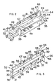
- FIG. 2 shows mainly the inside characteristics of the member 24 of the bracket.
- the member is formed of cold rolled mild carbon steel having upper and lower platforms 34 and 36, respectively, for supporting two stacked enclosure cases, not shown.
- a vertically extending stop member 38 At the inner end of the platform 36 there is provided a vertically extending stop member 38, the upper end of which projects above the upper platform 34 an amount sufficient to serve as a stop for a case supported by the upper platform 34, as the lower part of the member 38 will function as a stop for a case carried by the lower platform 36.
- the platforms 34 and 36 each have rearwardly extending portions 40 that terminate at the very end of the bracket member and serve to add support and rigidity to the member.
- the members 24 and 26 only support a relatively small portion of the underside of the cases at their two opposite corners, one of the cases in its entirety being shown in FIG. 8.
- the outer longitudinal side of the bracket member 24 is formed with a vertical wall 42 to which the platforms 34 and 36 are made an integral part, the wall extending the full length of the member.
- FIG. 2 shows that the tabs 32 are arranged to project perpendicularly beyond the wall 42 and also outwardly to the left and right and parallel thereto.
- the tabs have some holes 41 that are closed and others that have open slots for convenience of mounting and alignment when the two members 24 and 26 that make up the bracket are secured to the posts 12 by the screws 30.
- the perpendicular projections allow the vertical wall 42 to be placed a desired distance away from the adjacent vertical inside surfaces of an associated post 12.
- the upper surface 44 of the bracket member 24 is maintained below the arms of a torsion shaft, to be described below, but the height of the member and the positions of the two platforms 34 and 36 are such that the tabs 32 align longitudinally with the arms and thus avoid using any of the inner space of the rack because of the employment of the latching arrangement.
- FIG. 2 shows that both the platforms 34 and 36 and the vertical wall 42 are provided with a number of openings 46 that allow for cooling of the internal components of the case.
- FIG. 2 also indicates by the four outlined areas 48 that each platform has two areas which will be contacted by the feet 49 of two cases, one foot for each case only being identified, which are supported by their respective platforms.
- the bracket's open front end and the lead in portions of the platforms allow the insertion as a simple quick operation.
- the two platforms of the members 34 and 36 are separated vertically a desired distance from each other to allow the installing of the two stacked cases. The same result is accomplished by the distance maintained between the upper platforms 34 and the computer component mounted above the bracket.
- the various sections that make up both sides of the bracket, in a customary manner, are interconnected by cold forming and tig welding.
- FIG. 3 illustrates the outer side, that is, the side that faces the post 12, of the right hand cooperative member 26 of the bracket 28.
- the inside surfaces of the projecting tabs 32 are seen along with the inside surfaces of the closed and slotted holes 41.
- the outside takes the form of upper and lower sections indicated at 52 and 54, respectively, designed to accommodate two stacked enclosure cases.
- these reference numbers will also be used to designate the inside sections formed by the platforms 34 and 36.
- each of the sections 52 and 54 there is provided four outwardly projecting horizontal in-line tabs 56 having open bottoms and a single outwardly projecting in-line tab 58 being arranged adjacent the front end of the bracket, i.e. to the right as one views FIG. 3.
- This latter tab has an open top, as distinguished from the bottom openings of the former tabs.
- the size of the openings of the four tabs 56 and 58 is made to accommodate the diameters of the bracket receiving portions of associated torsion shafts 60 of two latching mechanisms, sometime hereinafter referred to as a latch, 62 shown arranged in and supported by the bracket members in FIGS. 2 and 3.
- each shaft is formed with two spaced apart laterally extending arm sections, each comprising a pair of spaced apart arms 66 between which a latching portion or cross member 67 extends when referring to the upper section 52, the case, not shown, slides under the overhanging inwardly projecting cross members 67 of the arm sections when the handle 64 is in the indicated vertical position.
- FIG. 3 shows the cooling openings 46 in the vertical wall 42.
- the arm sections 66 of the torsion shafts 60 are located on the shafts so as to be generally directly across from where the feet of the cases are supported by the platforms 34 and 36. This design allows the latching force of an arm section to be taken directly from the top of a case into its foot located directly below the point of the application of the force and hence into the associated platform, and in this way isolates the latching force from the rest of the plastic wall of the case.
- each section 52 and 54 there is provided for each section 52 and 54 relatively large rectangularly shaped flat tabs or containing members 68 projecting perpendicularly from the vertical wall 42 towards the post 12 of the rack 10 but spaced therefrom. These tabs 68 fall behind the handles 64 of the torsion shafts 60.
- the handles of each member 24 and 26 move towards the adjacent inside surface of an associated post 12, in which the bars 21 and tabs 32 space the handles far enough away from the posts sufficient to allow the necessary movements of the handles to effect the latching.
- a horizontally extending detail 70 having two stepped or indented portions 72 and 74, the depths of the steps being dimensioned to receive in a locking manner a portion of the handle 64 of an associated torsion shaft 60.
- the details 70 are shown to have wider portions on the side nearest an associated handle when in its vertical position, which portion causes the handle to spring outwardly when moved into the latching position, after which the handle will spring back into one of the step portions 72 and 74.
- the handles move from generally vertical positions, to positions approaching horizontal positions, the latter positions being the latching positions, in which the cross members 67 are caused to contact the top adjacent corner of the case.
- the two step portions 72 and 74 serve to lock an associated torsion shaft in its latched position and allow for the selection of two latching forces, depending on which step in which the handle is located.
- FIG. 6 shows that the inner end of each shaft of the latching mechanism 62 is provided with a thrust washer 76, the inner surface of which engages the adjacent outer surface of the adjacent tab 56, which contact limits the axial movement of the shaft in a direction from left to right, but yet still allows free and easy rotation of the shaft.
- the shaft is limited in its movement in the opposite direction by the handle 64 contacting the tab 68.
- a clearance is provided between the washer 76 and tab 56 and the handle 64 and tab 68.
- the handles are formed in the shape of open rectangles for ease of manipulation by hand.
- FIGS. 6 and 7 best illustrate the radial offset relationship of the pairs of spaced arm sections 66 and cross members 67 of each torsion shaft 60.
- the shaft shown in these figures is for the member 24, which means the shaft and cross members rotate towards one viewing FIG. 6 from the unlatched illustrated position to the latched position.
- the cross members are offset with respect to their radii relative to the shaft 60 as indicated in FIG. 7, where the cross member 67B, closest to the handle 64, is shown to be slightly offset with respect to the cross member 67A.
- the cross members 67A of each shaft contact the case first after which the case is contacted by the cross members 67B.
- the degree of offset in the form shown measured by the two different angles of the cross members, and further defined by the acute angle formed by two lines drawn through the parallel axes of the cross members and the parallel axis of the shaft, amounts to approximately eleven degrees, which may range between plus or minus 3 degrees in the shaft being illustrated.
- the reference to the acute angle is understood to mean the angle formed when the two lines are viewed as being in a common vertical plane passing transversely through the longitudinal axis of the torsion shaft 60.
- FIG. 7 indicates the shape of the arms of one of the shafts that allows the cross members arranged at their outer ends to apply the latching force to one of the upper corners of the case.
- the cross member 67A On rotation of the handle of the member 24 in a counterclockwise direction, i.e. into the paper so to speak, the cross member 67A is caused to contact the case first, after which on a slight additional counterclockwise rotation the cross member 67B is brought into engagement with the top surface of the case.
- a desired and predetermined torque is placed on the torsion shaft sufficient to accomplish an effective constant latching force securing the case to the rack 10.
- the torsion shaft 60 is made out of high carbon or alloy spring steel tempered wire.
- an approximation of the diameter of the shaft is 4.76 mm, the length of the shaft 420 mm, the throw of the arms 32 mm, and the length of the handle 93 mm.
- the approximate weight of the case can be 12.7 kg.
- the length of the handles of each member 24 and 26 will allow their lower ends to engage the details 70 of the bracket 28.
- the latching surfaces of the cross members 67 are coated with a plastic to improve their gripping affect with the case. The same coating, for the same reason, may be provided for the handles.
- FIG. 8 is designed to indicate that an enclosure case 82 is provided with four perimetric located raised feet 49 which engage the spaced areas 48 of the platforms 34 and 36 and play a role in transferring to the platforms the latching force and in so doing protecting the plastic case from damage from this force.
- the outer shell of the case is formed out of a plastic of the type customarily used in the computer industry.
- the case 82 being a desk top type, is provided with the four feet 49 at the four corners of the case, the feet also being formed of plastic in the general form of either a single elongated piece or two such pieces arranged perpendicularly and joined together.
- the portions of the feet that contact the platforms are made out of rubber like insert members.
- An example of the size of the length of a section of a foot for a case measuring approximately 40 cm square would be 3 cm. While the bracket has been shown to support a case in a horizontal position, the bracket may be positioned to support a case in a vertical position.
- the case 82 can be slid over the particular cooperative pairs of platforms 34 and 36 to be used to support the case in the rack 10.
- the upper surface 88 of the case 82 will move free of any contact by the arms 66 and cross members 67 of the torsion shafts 60 which will be in their ambushed positions.
- the stop members 38 of the bracket 28 will properly position the case longitudinally on the platforms being used.
- the handles 64 of the torsion shafts 60 of a bracket 28 are rotated to cause the cross members 67 to move inwardly and particularly downwardly towards the center of the rack, where they will contact the two opposite upper corners of the case 82 and latch the case to the rack under the torsion forces created in the two shafts by the sequential latching contact of the cross members 67A and 67B of each shaft.
- the handles will be positioned in one of the steps 72 or 74 of an associated detail 70 of the bracket 28 to assure that the torsion force on each torsion shaft will be maintained as long as the handles remain locked. This locked condition will withstand the usually severe pre-shipment drop and vibration testing and similar forces that may reasonably be expected during shipment and use.
- the described action is simply reversed.
- the torsion shaft can take different forms, for example, when employed with very small size cases, a single cross member need only be used, in larger cases three or more cross members may be desirable. Also, instead of the disclosed bracket other forms may be employed.
- the torsion shaft may be used without a rack or bracket, in which, for example, the shaft may be mounted directly on the chassis of a case for internally securing a computer component to the chassis.
Landscapes
- Engineering & Computer Science (AREA)
- Microelectronics & Electronic Packaging (AREA)
- Casings For Electric Apparatus (AREA)
- Details Of Rigid Or Semi-Rigid Containers (AREA)
Claims (18)
- Einrastanordnung zum Einrasten einer Computerkomponente (82) an einem Rahmen (10), gekennzeichnet durch: ein Drehwellenelement (60), das drehbar an einem Träger (24,26) angebracht ist, wobei der genannte Träger (24,26) an dem genannten Rahmen (10) befestigt werden kann, einen ersten Teil des genannten Wellenelements (60), der einen Einrastmechanismus (62) bildet, welcher einen sich seitlich erstreckenden, einen Einrastteil (67) umfassenden Armabschnitt (66) aufweist, einen zweiten Teil des genannten Wellenelements (60), der ein Element (64) zur Verwendung beim Drehen des genannten Wellenelements (60) umfaßt, um den genannten Einrastteil (67) in eine eingerastete Position hinein und aus derselben heraus zu bringen, und einen dritten Teil des genannten Wellenelements (60), der ein zweites Element (62) zum Erzeugen einer Einrastkraft an dem genannten Einrastteil (67) umfaßt, wenn sich dieser in der genannten eingerasteten Position befindet.
- Einrastanordnung nach Anspruch 1, in der das genannte Wellenelement (60) eine Längsachse aufweist und wenigstens zwei seitliche Armabschnitte (66) umfaßt, wobei jeder der genannten Armabschnitte (66) einen genannten Teil (67) umfaßt und jeder genannte Einrastteil (67) sich parallel zu der genannten Längsachse erstreckt, wobei die genannten Armabschnitte (66) voneinander entfernt entlang der genannten Längsachse des genannten Wellenelements (60) beabstandet sind und so angeordnet sind, daß sie ein unterschiedliches Winkelverhältnis zueinander im Verhältnis zu der genannten Achse haben.
- Einrastanordnung nach Anspruch 2, bei der das genannte unterschiedliche Winkelverhältnis in den Bereich von 8 bis 14 Grad wie gemessen durch einen spitzen Winkel fällt, der durch Linien begrenzt wird, die durch die Längsachse des genannten Wellenelements (60) und die Längsachsen der genannten Einrastteile (67) der genannten Armabschnitte gezogen sind.
- Einrastanordnung nach Anspruch 2, bei der das genannte Wellenelement (60) aus einem vergütetem Federstahl gebildet ist und konstruiert und angeordnet ist, um als ein Drehstab arbeiten zu können, wenn es während eines Einrastvorgangs einer durch die genannten Einrastteile der genannten Armabschnitte (66) erzeugten Drehbeanspruchung ausgesetzt wird.
- Einrastanordnung nach Anspruch 1, weiter gekennzeichnet durch:einen Halter (28) mit einer Vielzahl von Trägern (24,26), wobei jeder Träger (24,26) einen Teil (56) umfaßt, der konstruiert und angeordnet ist, um das genannte Drehwellenelement (60) aufzunehmen, so daß das genannte Spannungswellenelement (60) [sic] im Verhältnis zu dem genannten Teil (56) bewegbar ist, wobei das genannte Drehwellenelement den genannten Einrastteil (67) umfaßt, der konstruiert und angeordnet ist, um die genannte Computerkomponente (82) an dem genannten Halter (28) einzurasten, undwobei das genannte Wellenelement (60) das genannte zweite Element (62) einschließt, um Bewegung des genannten Einrastteils in eine eingerastete Position hinein und aus derselben heraus mit der genannten Computerkomponente (82) zu bewirken, und um eine Einrastkraft an dem genannten Einrastteil zu erzeugen, wenn er sich in der genannten eingerasteten Position befindet.
- Einrastanordnung nach Anspruch 5, die weiter dadurch gekennzeichnet ist, daß:der genannte Rahmen (10) einen Befestigungsteil (23) umfaßt,der genannte Träger (24, 26) einen zweiten Teil (32) umfaßt, der an dem genannten Befestigungsteil (23) des genannten Rahmens (10) angebracht werden kann.
- Einrastanordnung nach Anspruch 6, dadurch gekennzeichnet, daßdie genannte Computerkomponente (82) einen Teil (88) umfaßt, der durch das genannte zweite Element (62) zum Bewirken von Bewegung in einer Weise ergriffen werden kann, um den genannten Einrastteil (67) in der genannten eingerasteten Position unter einer vorbestimmten Einrastkraft zu halten, und eine Computerkomponente (82) umfaßt, die ein Umhüllungsbehältnis mit einer intern installierten Leiterplatte (9), zentralen Verarbeitungseinheit (11) und Speichereinheiten (13) umfaßt,der genannte Träger (24,26) Öffnungen (46) mit solchen Abmessungen umfaßt, um Zirkulation von Luft neben der genannten Computerkomponente (82) zuzulassen.
- Einrastanordnung nach Anspruch 1, in der der genannte Rahmen (10) voneinander beabstandete Ständer (12) umfaßt, die jeweils Befestigungsteile (23) einschließen, wobei der genannte Halter (28) voneinander beabstandete Befestigungsteile (32), die konstruiert und angeordnet sind, um an einem anderen der genannten Befestigungsteile (23) der genannten Ständer (12) befestigt zu werden, und Befestigungseinrichtungen (30) zum Bewirken der genannten Befestigung des genannten Halters (28) an den genannten Ständern (12) umfaßt, wobei der genannte Halter (28) einen eine Computerkomponente tragenden Teil (34) zum Halten der genannten Komponente (82) und eine äußere ergreifbare Oberfläche (88) umfaßt, die, wenn die genannte Komponente (82) durch den genannten tragenden Teil (34) des genannten Halters (28) gehalten wird, in einer Position präsentiert wird, um durch den genannten Armabschnitt (66) ergriffen zu werden,der genannte Einrastteil (67) konstruiert und angeordnet ist, um die genannte Außenfläche (88) der genannten gehaltenen Komponente (82) zu ergreifen, um die genannte Komponente (82) an dem genannten Halter (28) und folglich an dem genannten Rahmen (10) einzurasten.
- Einrastmechnismus nach Anspruch 8, bei dem das genannte Wellenelement (60) einen zweiten Armabschnitt (66) umfaßt, der in einem beabstandeten Verhältnis zu dem genannten ersten Armabschnitt (66) an dem genannten Wellenelement (60) angeordnet ist,die genannten Armabschnitte (66) jeweils ähnliche Teile enthalten, die konstruiert sind, um sich in Richtung verschiedener Teile der genannten Komponente (82) zu erstrecken, wenn diese durch den genannten Halter (28) getragen wird, wobei jeder genannte Armabschnitt (66) in einem genannten Einrastteil (67) endet,jeder der genannten Einrastteile (67) ein Querelement (67a) aufweist, wobei die genannten Querelemente (67a,67b) jedes genannten Armabschnitts (66) konstruiert und angeordnet sind, um ein unterschiedliches Winkelverhältnis zueinander im Verhältnis zu der Längsachse des genannten Wellenelements (60) anzunehmen, so daß bei Drehung des genannten Wellenelements eines der genannten Querelemente (67a,67b) in Gebrauch veranlaßt wird, mit einem der genannten Teile der genannten Komponente (82) in Eingriff zu treten, bevor das genannte andere Querelement veranlaßt wird, mit dem anderen der genannten Teile der genannten Komponente (82) in Eingriff zu treten, und wobei, nachdem das genannte eine Querelement veranlaßt wurde, in Eingriff zu treten, das genannte Wellenelement (60) einer Torsionskraft ausgesetzt wird, bis das genannte andere Querelement veranlaßt wird, in Eingriff zu treten, und wobei nach dem genannten letzten genannten Eingriff das genannte Wellenelement (60) weiterhin einer Torsionskraft ausgesetzt ist.
- Einrastanordnung nach Anspruch 9, bei der der genannte Rahmen (10) zwei zusammenwirkende Paare der genannten Ständer (12) umfaßt, wobei jeder der genannten Ständer (12) einen genannten Befestigungsteil (23) umfaßt, wobei der genannte Halter (28) zwei der genannten Träger (24,26) umfaßt, wobei ein genannter beabstandeter Befestigungsteil (32) des genannten Halters (28) für jeden der genannten Träger (24,26) vorgesehen ist, wobei die genannten Befestigungsteile (32) jedes genannten Trägers (24,26) an einem anderen der genannten Befestigungsteile (23) der genannten Paare von genannten Ständern (12) befestigt sind, so daß die genannten Träger (24,26) an einem anderen der genannten Paare befestigt werden und direkt einander gegenüber angeordnet sind, wobei jeder genannte Träger (24,26) ein genanntes Wellenelement (60) und ein Wandelement (42) umfaßt, wobei der tragende Teil (40) jedes genannten Trägers (24,26) eine erste Plattform (34) einschließt, die durch jedes genannte Wandelement (42) in einer Weise getragen wird, um allgemein in gleicher Ebene und parallel zueinander zu sein, wobei die genannten Plattformen (34,36) Halteoberflächen einer Abmessung umfassen, die zum Halten von Teilen der gegenüberliegenden Seiten der genannten Komponente (82) ausreicht, und wobei die genannten Träger (24,26) gemeinsame Enden umfassen, die konstruiert und angeordnet sind, um die genannte Komponente (82) aufzunehmen.
- Einrastanordnung nach Anspruch 10, bei der die genannte Komponente (82) eine erste genannte Komponente (82) aufweist, wobei jeder genannte Träger (24,26) eine zweite genannte Plattform (36) aufweist, die von der ersten genannten Plattform (34) der genannten Träger (24,26) in einer Weise beabstandet ist, daß die genannten beiden Träger (24,26) eine zweite genannte Komponente (82) in einem gestapelten, übereinander angeordneten Verhältnis zu der genannten ersten Komponente (82) halten, wobei die zweiten genannten Plattformen (36) Halteoberflächen einer Abmessung umfassen, die ausreicht, um Teile der gegenüberliegenden Seiten der genannten zweiten Komponente (82) zu halten, und wobei die genannten gemeinsamen Enden jedes der genannten Träger (24,26) konstruiert und angeordnet sind, um die genannte zweite Komponente (82) aufzunehmen.
- Einrastmechanismus nach Anspruch 11, bei dem jeder genannte Träger (24,26) ein Anschlagelement (38) zum Positionieren ihrer genannten gehaltenen Komponenten (82) auf zugeordneten genannten Plattformen (34,36) umfaßt,jeder genannte Träger (24,26) einen genannten Einrasthalteteil umfaßt, der voneinander beabstandete, allgemein ausgerichtete Aufhänger (56) umfaßt, wobei jeder genannte Aufhänger (56) einen Teil umfaßt, der konstruiert und angeordnet ist, um einen anderen Teil des Wellenelements (60) aufzunehmen und drehbar zu halten, und wobei das genannte Wellenelement (60) aus einem vergüteten Federstahl gebildet ist.
- Verfahren zum Herstellen einer Befestigungsanordnung für eine Einheit eines Computersystems (82), wobei die genannte Anordnung einen Rahmen (10), einen Halter (28) und einen Einrastteil (67) umfaßt, wobei die genannte Einheit (82) erste und zweite äußere ergreifbare Oberflächen aufweist, wobei das Verfahren gekennzeichnet ist durch die Schritte:Bilden von Halteoberflächen (23) an dem genannten Rahmen,Bilden des genannten Halters (28), um zwei Seitenelemente zu umfassen (24,26),Bilden jedes genannten Seitenelements (24,26), um eine Halteoberfläche (32) einzuschließen, die konstruiert und angeordnet ist, um mit einer anderen der genannten Halteoberflächen (23) des genannten Rahmens (10) in einer Weise zusammenzuwirken, um die genannten Seitenelemente (24,26) an dem genannten Rahmen (10) zu befestigen, in dem die genannten Seitenelemente (24,26) in gleicher Ebene und parallel zueinander sind,Bilden jedes genannten Seitenelements (24,26), um Halteteile (34,36) zu umfassen, die konstruiert und angeordnet sind, um einen anderen Teil der genannten ersten äußeren ergreifbaren Oberfläche der genannten Einheit (82) zu halten,Bilden eines Einrastaufnahmeteils (56) an jedem der genannten Seitenelemente (24,26),Bilden eines genannten Einrastteils (67) für jedes genannte Seitenelement (24,26) aus einer Metallwelle (60), einschließlich Bilden eines Arms (66), eines Halteraufnahmeteils (62) und eines Griffs (64) in voneinander beabstandetem Verhältnis als Teil jeder genannten Welle (60);Bilden jedes genannten Halteraufnahmeteils (62) aus einem zugeordneten Einrastteil (67), um durch den genannten Einrastaufnahmeteil (56) eines zugeordneten Seitenelements (24,26) aufgenommen zu werden,Bilden und Anordnen jedes genannten Armabschnitts (66) in einer solchen Weise, daß, wenn die genannte Einheit (82) durch die genannten Halteteile (34,36) der genannten Seitenelemente (24,26) gehalten wird, verschiedene Teile der genannten zweiten äußeren ergreifbaren Oberfläche der genannten Einheit (82) neben den genannten Armabschnitten (66) angeordnet sind,Bilden jedes genannten Armabschnitts (66), so daß derselbe einen Teil einschließt, der angeordnet ist, um einen anderen der genannten anderen Teile der genannte zweiten äußeren ergreifbaren Oberfläche der genannten Einheit (82) in einer Weise zu berühren, um die genannte Einheit (82) an dem genannten Halter (28) und folglich an dem genannten Rahmen (10) einzurasten,Bilden der genannten Einrastteile der genannten Armabschnitte (66) in einer Weise, um eine Einrastkraft an der genannten Einheit zu erzeugen, wenn diese an dem genannten Halter (28) eingerastet ist, undBilden jedes genannten Griffs (64), um eine Drehung eines zugeordneten Arms (66) zu bewirken, um so einen zugeordneten Armabschnitt (66) mit einem anderen der genannten anderen Teile der genannten zweiten äußeren ergreifbaren Oberfläche der genannten Einheit (82) in Kontakt und aus demselben heraus zu bringen.
- Verfahren nach Anspruch 13, gekennzeichnet durch die zusätzlichen Schritte:Bilden des genannten Rahmens (10) als ein Gestell (10) mit voneinander beabstandeten Pfosten (12), die zwischen sich eine Öffnung zum Aufnehmen einer genannten Einheit (82) bilden,Bilden einer genannten Halteoberfläche (23) auf jedem genannten Pfosten (12), Bilden jeder genannten Welle als eine Drehwelle (60),Bilden jedes genannten Armabschnitts (66) in der Form von zwei Armen (66), die entlang der Achse der genannten Welle (60) voneinander beabstandet sind,Bilden jedes genannten Einrastteils (67), so daß er parallel zu der genannten Achse einer zugeordneten Welle (60) ist undAnordnen der genannten Einrastteile (67) einer zugeordneten Welle (60), um ein unterschiedliches Winkelverhältnis zueinander im Verhältnis zu einer zugeordneten Wellenachse zu haben, undVeranlassen jeder genannten Drehwelle (60), durch einen zugeordneten Halter (28) in einer Weise getragen zu werden, um den genannten Armabschnitt (66) der genannten Einrastteile (67) in den genannten eingerasteten Positionen unter einer Drehkraft zu halten.
- Verfahren nach Anspruch 14, das die zusätzlichen Schritte aufweist:Bilden jeder genannten Welle (60) aus einem vergüteten Federstahl,Bilden, Konstruieren und Anordnen eines Halteelements (52,54) für jede Welle, um so durch einen zugeordneten Griff ergriffen zu werden, daß eine zugeordnete Welle (60) in der genannten Einrastposition gehalten wird, und Bilden der genannten Einheit (82) als ein Umhüllungsbehältnis und Installieren einer Leiterplatte (9), einer zentralen Verarbeitungseinheit (11) und von Speichereinheiten (13) in dem genannten Behältnis.
- Verfahren nach Anspruch 15, in dem die genannte Befestigungsanordnung wenigstens zwei Behältnisse umfaßt, wobei jedes Behältnis ausgeführt ist, um Computerkomponenten zu enthalten, welche Anordnung gekennzeichnet ist durch die Schritte:Unterteilen des genannten Gestells (10) in Bereiche, die zum Aufnehmen eines anderen der genannten Behältnisse (82) in übereinander angeordnetem Verhältnis zueinander geeignet sind,Anbringen in wenigstens einem der genannten Bereiche eines genannten Halters (28) in einer Weise, um wenigstens eine der Seiten von einem der genannten Behältnisse (82) zu halten,Befestigen der genannten Welle (60) an dem genannten Halter (28) in einer Weise, um die genannten Einrastteile (67) in eine eingerastete Position zu bringen, wobei ein genanntes Behältnis (82) an dem genannten Halter (28) und folglich an dem genannten Gestell (10) eingerastet wird, undAussetzen der genannten Welle (60) einer Torsionskraft, wenn sie sich in der genannten eingerasteten Position befindet, um den genannten Einrastteil in der genannten eingerasteten Position zu halten.
- Verfahren nach Anspruch 16, gekennzeichnet durch die zusätzlichen Schritte:Befestigen der genannten Welle (60) ohne die Verwendung eines Werkzeugs an dem genannten Halter (28),Bilden der genannten Welle (60), um zwei voneinander beabstandete Einrastteile (67) aufzuweisen, und Anordnen der genannten beiden Einrastteile (67), um die genannte Torsionskraft der genannten Welle (60) durch aufeinanderfolgenden Eingriff der genannten beiden Einrastteile (67) der genannten Welle (60) mit dem genannten einen Behältnis (82) zu erzeugen.
- Verfahren nach Anspruch 16, bei dem die genannte Anordnung ein Halteelement (52,54) umfaßt, gekennzeichnet durch die zusätzlichen Schritte: wenn die genannte Welle sich in ihrer eingerasteten Position befindet, Veranlassen der genannten Welle, mit dem genannten Halteelement in einer Weise in Eingriff zu treten, um die genannte Welle in ihrer eingerasteten Position unter der genannten Torsionskraft zu halten.
Applications Claiming Priority (2)
| Application Number | Priority Date | Filing Date | Title |
|---|---|---|---|
| US248023 | 1981-03-26 | ||
| US08/248,023 US5546277A (en) | 1994-05-24 | 1994-05-24 | Computer component torsional latching mechanism and method |
Publications (3)
| Publication Number | Publication Date |
|---|---|
| EP0684540A2 EP0684540A2 (de) | 1995-11-29 |
| EP0684540A3 EP0684540A3 (de) | 1997-03-05 |
| EP0684540B1 true EP0684540B1 (de) | 1999-06-30 |
Family
ID=22937332
Family Applications (1)
| Application Number | Title | Priority Date | Filing Date |
|---|---|---|---|
| EP19950303062 Expired - Lifetime EP0684540B1 (de) | 1994-05-24 | 1995-05-04 | Vorrichtung und Verfahren zur Halterung eines Computerbauelementes |
Country Status (4)
| Country | Link |
|---|---|
| US (1) | US5546277A (de) |
| EP (1) | EP0684540B1 (de) |
| JP (1) | JPH0854963A (de) |
| DE (1) | DE69510497T2 (de) |
Families Citing this family (23)
| Publication number | Priority date | Publication date | Assignee | Title |
|---|---|---|---|---|
| US5724227A (en) * | 1996-03-19 | 1998-03-03 | Gateway 2000, Inc. | Rotatable drive bay module for a computer cabinet |
| USD440210S1 (en) | 1997-08-07 | 2001-04-10 | Ortronics, Inc. | Cable management rack |
| US6021909A (en) * | 1998-11-13 | 2000-02-08 | Hewlett-Packard Company | Equipment enclosure rack support rail system |
| US6324062B1 (en) * | 1999-04-02 | 2001-11-27 | Unisys Corporation | Modular packaging configuration and system and method of use for a computer system adapted for operating multiple operating systems in different partitions |
| US6422399B1 (en) | 2000-11-21 | 2002-07-23 | Dell Products L.P. | Rack system and method having tool-less releasable arm assembly |
| US6554142B2 (en) | 2001-07-27 | 2003-04-29 | Dell Products L.P. | Variable mount rack system arm assembly |
| US6644480B2 (en) * | 2002-01-30 | 2003-11-11 | Hewlett-Packard Development Company, L.P. | Adjustable rackmount assembly with locking key |
| US6769551B2 (en) | 2002-07-26 | 2004-08-03 | Dell Products L.P. | System and method for utilizing non-dedicated rack space |
| US6902069B2 (en) * | 2002-10-23 | 2005-06-07 | Dell Products L.P. | System and method for rack cable management |
| US6866154B2 (en) * | 2002-12-03 | 2005-03-15 | Dell Products L.P. | Tool-less attachment bracket |
| US8607993B2 (en) | 2003-03-21 | 2013-12-17 | Dell Products L.P. | Tool-less cable management attachment bracket and method of use |
| US7168576B2 (en) * | 2003-03-21 | 2007-01-30 | Dell Products L.P. | Tool-less cable management attachment bracket and method of use |
| US7097047B2 (en) * | 2003-09-30 | 2006-08-29 | Dell Products L.P. | Cable management flip tray assembly |
| US7038918B2 (en) * | 2004-03-03 | 2006-05-02 | Hubbell Incorporated | Midspan patch panel with compensation circuit for data terminal equipment, power insertion and data collection |
| KR20070004816A (ko) * | 2004-03-03 | 2007-01-09 | 허브벨 인코포레이티드 | 데이터 터미널 설비, 파워 삽입 및 데이터 수집을 위한회로 분리부를 구비한 미드스팬 패치 패널 |
| US20050195583A1 (en) * | 2004-03-03 | 2005-09-08 | Hubbell Incorporated. | Midspan patch panel with circuit separation for data terminal equipment, power insertion and data collection |
| KR100822281B1 (ko) * | 2006-11-29 | 2008-04-16 | 미래산업 주식회사 | 반도체 소자 테스트 핸들러용 캐리어모듈 |
| CN101593001B (zh) * | 2008-05-31 | 2013-04-03 | 光宝电子(广州)有限公司 | 固定构件及使用该固定构件的计算机机壳 |
| USD603628S1 (en) * | 2008-09-22 | 2009-11-10 | Trompeter Electronics, Inc. | Hinged demarcation panel for front cabinet access |
| USD604065S1 (en) * | 2008-09-22 | 2009-11-17 | Trompeter Electronics, Inc. | Hinged demarcation panel for front cabinet access |
| US9814156B2 (en) | 2015-09-25 | 2017-11-07 | Innovation First, Inc. | Server rack system for mounting equipment |
| US9456520B1 (en) * | 2015-09-25 | 2016-09-27 | Innovation First, Inc. | Server rack system for mounting equipment |
| JP6704634B2 (ja) * | 2015-12-25 | 2020-06-03 | 日東工業株式会社 | 電気電子機器収納用箱の基台増設構造 |
Family Cites Families (9)
| Publication number | Priority date | Publication date | Assignee | Title |
|---|---|---|---|---|
| US2967080A (en) * | 1958-07-08 | 1961-01-03 | United Aircraft Corp | File cabinet locking device |
| NL6910857A (de) * | 1968-07-16 | 1970-01-20 | ||
| US3863767A (en) * | 1972-02-04 | 1975-02-04 | William Guy Garwood | Bicycle security rack |
| CA1084096A (en) * | 1978-09-20 | 1980-08-19 | Storwal International Inc. | Cam for cabinet locking system |
| US4524872A (en) * | 1981-03-30 | 1985-06-25 | Chamberlain Lewis W | Universal locking device |
| FR2579402B1 (fr) * | 1985-03-22 | 1988-04-29 | Thomson Csf | Dispositif d'insertion et d'extraction de cartes electroniques |
| DE3920353A1 (de) * | 1989-06-19 | 1990-12-20 | Siemens Ag | Geruest fuer einen schaltschrank aus mehrfach abgewinkelten profilelementen mit einseitig offenem hohlprofil |
| US4979909A (en) * | 1989-12-18 | 1990-12-25 | Hewlett-Packard Company | Release apparatus for computer mass storage devices |
| US5385039A (en) * | 1993-01-21 | 1995-01-31 | Steelcase Inc. | Electronic lock |
-
1994
- 1994-05-24 US US08/248,023 patent/US5546277A/en not_active Expired - Lifetime
-
1995
- 1995-05-04 DE DE69510497T patent/DE69510497T2/de not_active Expired - Fee Related
- 1995-05-04 EP EP19950303062 patent/EP0684540B1/de not_active Expired - Lifetime
- 1995-05-24 JP JP14841595A patent/JPH0854963A/ja active Pending
Also Published As
| Publication number | Publication date |
|---|---|
| DE69510497T2 (de) | 2000-01-05 |
| US5546277A (en) | 1996-08-13 |
| DE69510497D1 (de) | 1999-08-05 |
| JPH0854963A (ja) | 1996-02-27 |
| EP0684540A2 (de) | 1995-11-29 |
| EP0684540A3 (de) | 1997-03-05 |
Similar Documents
| Publication | Publication Date | Title |
|---|---|---|
| EP0684540B1 (de) | Vorrichtung und Verfahren zur Halterung eines Computerbauelementes | |
| US6021047A (en) | Computer and a rack mount system and method for a computer | |
| US8528872B2 (en) | Equipment enclosure kit and assembly method | |
| US5135197A (en) | Equipment security method and apparatus | |
| US7472970B2 (en) | Equipment enclosure kit and assembly method | |
| US20050274680A1 (en) | Mounting bracket | |
| EP0665554B1 (de) | Träger für Rechner-Festplatte oder dergleichen | |
| US5791498A (en) | Rack mount mechanism having an angled bar-nut | |
| US5682291A (en) | Carrier for a computer device | |
| US5540339A (en) | Telecommunications wall rack | |
| US6404624B1 (en) | Structure for mounting electronic devices to a computer main body | |
| US20020089829A1 (en) | Circuit board mounting apparatus and associated methods | |
| US20030034717A1 (en) | Computer case with an adjustable space | |
| US6980429B2 (en) | Device retention apparatus locking assembly | |
| US5587879A (en) | Mounting arrangement for computer hardware components and method | |
| US6292359B1 (en) | Component mount | |
| US5812377A (en) | Universal card cage assembly | |
| US6636418B1 (en) | Methods and apparatus for installing electronic cabinets using improved stabilization techniques | |
| US6385050B1 (en) | Component housing device | |
| JPH10111734A5 (de) | ||
| US4718632A (en) | Hold-down type mechanism | |
| US6323423B1 (en) | Housing for interconnected printed circuit boards | |
| US6757163B2 (en) | Computer having an auxiliary memory unit removably fastened on a fixing bracket | |
| JP3384645B2 (ja) | 電子装置構造 | |
| US20040223308A1 (en) | Electronic unit enclosure and method |
Legal Events
| Date | Code | Title | Description |
|---|---|---|---|
| PUAI | Public reference made under article 153(3) epc to a published international application that has entered the european phase |
Free format text: ORIGINAL CODE: 0009012 |
|
| AK | Designated contracting states |
Kind code of ref document: A2 Designated state(s): DE FR GB NL SE |
|
| PUAL | Search report despatched |
Free format text: ORIGINAL CODE: 0009013 |
|
| AK | Designated contracting states |
Kind code of ref document: A3 Designated state(s): DE FR GB NL SE |
|
| 17P | Request for examination filed |
Effective date: 19970503 |
|
| 17Q | First examination report despatched |
Effective date: 19970722 |
|
| GRAG | Despatch of communication of intention to grant |
Free format text: ORIGINAL CODE: EPIDOS AGRA |
|
| GRAG | Despatch of communication of intention to grant |
Free format text: ORIGINAL CODE: EPIDOS AGRA |
|
| GRAH | Despatch of communication of intention to grant a patent |
Free format text: ORIGINAL CODE: EPIDOS IGRA |
|
| GRAH | Despatch of communication of intention to grant a patent |
Free format text: ORIGINAL CODE: EPIDOS IGRA |
|
| GRAA | (expected) grant |
Free format text: ORIGINAL CODE: 0009210 |
|
| AK | Designated contracting states |
Kind code of ref document: B1 Designated state(s): DE FR GB NL SE |
|
| REF | Corresponds to: |
Ref document number: 69510497 Country of ref document: DE Date of ref document: 19990805 |
|
| ET | Fr: translation filed | ||
| PLBE | No opposition filed within time limit |
Free format text: ORIGINAL CODE: 0009261 |
|
| STAA | Information on the status of an ep patent application or granted ep patent |
Free format text: STATUS: NO OPPOSITION FILED WITHIN TIME LIMIT |
|
| 26N | No opposition filed | ||
| REG | Reference to a national code |
Ref country code: GB Ref legal event code: IF02 |
|
| PGFP | Annual fee paid to national office [announced via postgrant information from national office to epo] |
Ref country code: GB Payment date: 20030528 Year of fee payment: 9 Ref country code: FR Payment date: 20030528 Year of fee payment: 9 |
|
| PGFP | Annual fee paid to national office [announced via postgrant information from national office to epo] |
Ref country code: SE Payment date: 20030530 Year of fee payment: 9 Ref country code: NL Payment date: 20030530 Year of fee payment: 9 |
|
| PGFP | Annual fee paid to national office [announced via postgrant information from national office to epo] |
Ref country code: DE Payment date: 20030724 Year of fee payment: 9 |
|
| PG25 | Lapsed in a contracting state [announced via postgrant information from national office to epo] |
Ref country code: GB Free format text: LAPSE BECAUSE OF NON-PAYMENT OF DUE FEES Effective date: 20040504 |
|
| PG25 | Lapsed in a contracting state [announced via postgrant information from national office to epo] |
Ref country code: SE Free format text: LAPSE BECAUSE OF NON-PAYMENT OF DUE FEES Effective date: 20040505 |
|
| PG25 | Lapsed in a contracting state [announced via postgrant information from national office to epo] |
Ref country code: NL Free format text: LAPSE BECAUSE OF NON-PAYMENT OF DUE FEES Effective date: 20041201 Ref country code: DE Free format text: LAPSE BECAUSE OF NON-PAYMENT OF DUE FEES Effective date: 20041201 |
|
| GBPC | Gb: european patent ceased through non-payment of renewal fee |
Effective date: 20040504 |
|
| EUG | Se: european patent has lapsed | ||
| PG25 | Lapsed in a contracting state [announced via postgrant information from national office to epo] |
Ref country code: FR Free format text: LAPSE BECAUSE OF NON-PAYMENT OF DUE FEES Effective date: 20050131 |
|
| NLV4 | Nl: lapsed or anulled due to non-payment of the annual fee |
Effective date: 20041201 |
|
| REG | Reference to a national code |
Ref country code: FR Ref legal event code: ST |