EP0684580A2 - Positionssensor und Verfahren zur Rauschunterdrückung - Google Patents
Positionssensor und Verfahren zur Rauschunterdrückung Download PDFInfo
- Publication number
- EP0684580A2 EP0684580A2 EP95303051A EP95303051A EP0684580A2 EP 0684580 A2 EP0684580 A2 EP 0684580A2 EP 95303051 A EP95303051 A EP 95303051A EP 95303051 A EP95303051 A EP 95303051A EP 0684580 A2 EP0684580 A2 EP 0684580A2
- Authority
- EP
- European Patent Office
- Prior art keywords
- signal
- transmission
- noise
- loop coil
- sensing
- Prior art date
- Legal status (The legal status is an assumption and is not a legal conclusion. Google has not performed a legal analysis and makes no representation as to the accuracy of the status listed.)
- Withdrawn
Links
Images


Classifications
-
- G—PHYSICS
- G06—COMPUTING OR CALCULATING; COUNTING
- G06F—ELECTRIC DIGITAL DATA PROCESSING
- G06F3/00—Input arrangements for transferring data to be processed into a form capable of being handled by the computer; Output arrangements for transferring data from processing unit to output unit, e.g. interface arrangements
- G06F3/01—Input arrangements or combined input and output arrangements for interaction between user and computer
- G06F3/03—Arrangements for converting the position or the displacement of a member into a coded form
- G06F3/041—Digitisers, e.g. for touch screens or touch pads, characterised by the transducing means
- G06F3/046—Digitisers, e.g. for touch screens or touch pads, characterised by the transducing means by electromagnetic means
-
- G—PHYSICS
- G06—COMPUTING OR CALCULATING; COUNTING
- G06F—ELECTRIC DIGITAL DATA PROCESSING
- G06F3/00—Input arrangements for transferring data to be processed into a form capable of being handled by the computer; Output arrangements for transferring data from processing unit to output unit, e.g. interface arrangements
- G06F3/01—Input arrangements or combined input and output arrangements for interaction between user and computer
- G06F3/03—Arrangements for converting the position or the displacement of a member into a coded form
- G06F3/041—Digitisers, e.g. for touch screens or touch pads, characterised by the transducing means
- G06F3/0416—Control or interface arrangements specially adapted for digitisers
- G06F3/0418—Control or interface arrangements specially adapted for digitisers for error correction or compensation, e.g. based on parallax, calibration or alignment
Definitions
- This invention relates to a position transducer and a position sensing method of obtaining coordinates, or the like, of a specified position. More particularly, the present invention relates to a position transducer and a position sensing method suitable for use as, or for use with, a position transducer such as an input pen in which a received signal is prone to include large noise.
- a position transducer which determines coordinates of a position specified by a position indicator by detecting and analyzing a signal resulting from electromagnetic action between the position indicator and a loop coil, is widely used as an input device for use with a computer.
- the position transducer comprises a sensor section, consisting of a plurality of loop coils arranged side by side in a direction for position sensing, and a position indicator housing an electromagnetic coupling means such as a tuning circuit.
- the loop coil is substantially rectangular and therefore is longer in one axial direction.
- the sensor section is provided along each of the axes.
- an electromagnetic wave is generated by adequately selecting a loop coil and sending an A.C. signal from a transmitter to the loop coil, so that the tuning circuit housed in the position indicator is excited by the electromagnetic wave.
- an induced voltage develops when the loop coil receives the electromagnetic wave transmitted from the tuning circuit.
- a receiver connected to the loop coil receives the induced voltage as a receiving signal.
- the transmitter and the receiver are usually disposed on either longitudinal ends of the loop coils.
- An amplitude and a phase angle of each of object frequency components included in the received signal are obtained by processing the received signal.
- a loop coil to be selected is sequentially switched, and the above-mentioned operations for obtaining an amplitude and a phase angle are repeated. Coordinates of the specified position are obtained by executing computation on the basis of amplitude data or phase angle data obtained for each loop coil.
- a method utilizing analog phase detection (Unexamined Japanese Patent Publn. No. Sho-63(1988)-70326), and a method utilizing high-speed analog-to-digital conversion and discrete Fourier transformation (Unexamined Japanese Patent Publn. No. Hei-3(1991)-147012), and the like, are publicly known as examples of the method of sensing an amplitude and a phase angle of a received signal.
- a received signal is appropriately amplified by a pre-amplifier, or it is passed through an appropriate band-pass filter to eliminate noise.
- each phase of the signal is detected, whereby a real part and an imaginary part of an object frequency component included in the received signal are obtained.
- An amplitude and a phase angle of the frequency component are calculated by the use of the real part and the imaginary part.
- the position indicator is provided with a receiving mechanism, and the transmitter is provided on one longitudinal end of the loop coils.
- the position indicator is provided with a transmitting mechanism, and the receiver is provided on one longitudinal end of the loop coils.
- Hei-5(1993)-241722 discloses an apparatus, wherein when the position indicator is electromagnetically coupled to each of two loop coils which are not electromagnetically coupled with each other, an amplifier is self-excited by formation of a positive feedback loop, and a resulting excitation signal is received at one end of any one of the loop coils.
- an amplitude and a phase angle are calculated from a real part and an imaginary part of an object frequency component included in a received signal, and coordinates are obtained on the basis of the thus obtained amplitude and phase.
- Examples of such a position transducer are a tablet, a digitizer, and a touch display used as an input device of a computer.
- the received signal in the case of the position transducer in which a loop coil receives a signal, the received signal frequently includes various signals as noise other than a signal produced as a result of electromagnetic interaction between the loop coil and the position indicator.
- These noise sources can also cause the loop coil to bring about an induced voltage, and hence a signal, caused by the electromagnetic interaction between the loop coil and a position indicator to be detected, and the noise signals are received while both signals are added together. Some noise signals are stable, but the other noise signals can vary continuously.
- a band-pass filter is used for eliminating noise, and a received signal is passed through a filter set to a predetermined passband before being subjected to signal processing.
- a filter set is passed through a filter set to a predetermined passband before being subjected to signal processing.
- the band-pass filter it is possible to cut noise signals in a frequency range other than the passband.
- the band-pass filter it is impossible for the band-pass filter to eliminate a noise signal included in the passband range, i.e., a noise signal having a frequency close to the frequency of an object signal to be detected.
- Such a noise signal included in a received signal brings about an erroneous result in the computation of coordinates, thereby leading to a degraded position sensing accuracy.
- an object of the present invention is to provide a means and a method used with a position transducer for obtaining an amplitude level of a signal to be detected with high accuracy by eliminating a noise signal in a received signal having a frequency close to an object frequency.
- Another object of the present invention is to provide a means and a method used with a position transducer for obtaining an amplitude level of a signal to be detected with high accuracy by eliminating all of the noise signals included in a received signal.
- Still another object of the present invention is to provide noise signal elimination means and method used with a position transducer which can cope with various noise environments.
- a position transducer having a plurality of loop coils, arranged side by side in a direction of position sensing, and a position indicator for calculating coordinates, or the like, of the position indicator by sensing a signal developed in the loop coil as a result of electromagnetic interaction between the loop coil and the position indicator, and by carrying out signal processing on the basis of that signal
- the position transducer comprising: a transmission means which can selectively transmit a signal for inducing the electromagnetic interaction or can interrupt the transmission of this signal; a receiving means for receiving a signal from the loop coil; a memory means for storing a level of the received signal obtained as a result of the signal processing of the received signal; and a subtraction means for extracting an amplitude level corresponding to a signal, developed in the loop coil as a result of only the electromagnetic interaction, for each of the loop coils, by subtracting a noise level obtained from a signal received when the transmission means interrupts the transmission,
- the transmission means capable of transmitting a signal for inducing electromagnetic interaction, and the receiving means for receiving a signal developed in the loop coil are provided, if transmission is carried out while the position indicator is placed on a loop coil, electromagnetic interaction will develop between the position indicator and the loop coil situated below that position indicator. Eventually, it is possible to receive the signal developed in the loop coil.
- a received signal also includes a noise signal irrelevant to the presence or absence of the electromagnetic interaction in addition to the signal developed, resulting from electromagnetic interaction.
- the transmission means can interrupt transmission, it is also possible for the transmission means to receive a signal from a loop coil when transmission is not carried out.
- the signal received when no transmission is carried out includes only a noise signal.
- the signal received at this time i.e., the noise signal, is subjected to similar predetermined signal processing, whereby a noise level is obtained.
- This noise level is then stored in another memory means differing from the memory means in which the signal level is stored.
- An amplitude level to be detected (a component only resulting from electromagnetic interaction), and a noise level are included in the signal level while they are added together.
- the noise level includes only noise components. Therefore, it is possible to obtain only the amplitude level to be detected by subtracting the noise level from the signal level (hereinafter, a pure signal is called an "amplitude level”; a noise signal is called a “noise level”; and a mixed signal consisting of the pure signal and the noise signal is called a "signal level").
- the transmission means is disposed at least on one end of the loop coils.
- a signal for inducing electromagnetic interaction is transmitted from the transmission means disposed on one end of the loop coils to a loop coil, and a signal caused by the electromagnetic interaction between the position indicator and the loop coil is received from this loop coil.
- the position indicator is provided with the transmission means.
- a signal for inducing electromagnetic interaction is transmitted from the transmission means disposed on the position indicator, and a signal resulting from the electromagnetic interaction between the position indicator and the loop coil is received from this loop coil.
- the transmission means executes transmission in accordance with a sequence that includes several transmissions to one loop coil and at least one interruption of transmission, and the signal level is obtained from a signal received when transmission to one loop coil is carried out.
- the noise level is obtained from a signal received when the transmission to the one loop coil is interrupted.
- the transmission means executes transmission in accordance with the sequence that includes several transmissions to one loop coil and one interruption of transmission.
- a signal level is obtained from a signal received when transmission to one loop coil is carried out, and a noise level is obtained from a signal received when the transmission to the one loop is interrupted. Accordingly, it is possible to obtain only an amplitude level to be obtained by subtracting the noise level from the signal level including both the amplitude level to be detected and the noise level.
- the position transducer further comprises of a second memory means for previously storing a set of noise levels, each being obtained from a signal received from each of the plurality of loop coils while the transmission means is interrupting the transmission.
- the second memory means is further provided. While the transmission means is interrupting transmission, signals are respectively received from the plurality of loop coils, and a set of noise levels, each noise level being obtained from a signal received from each loop coil, are obtained and are previously stored in the second memory means. Thereafter, ordinary position sensing action is executed, and it is possible to obtain a pure amplitude level by subtracting a noise level of a corresponding loop coil stored in the second memory means from a signal level obtained from the received signal.
- the position transducer further comprises a plurality of memory blocks provided in the second memory means so as to correspond to a plurality of noise environments of the position transducer; a sensing means for previously storing a set of noise levels, each being obtained from a signal received from each of the plurality of loop coils in each noise environment, into each memory block and sensing different noise environments; and a selecting means for selecting one of the plurality of memory blocks in accordance with the noise environment sensed by the sensing means.
- a plurality of different memory blocks are provided in the second memory means so as to correspond to different noise environments of the position transducer.
- signals are previously received respectively from the loop coils for one of the plurality of noise environments, and a set of noise levels, each noise level being obtained from a signal received from each loop coil, are obtained and stored in any one of the plurality of noise blocks. Similar operation is carried out for each of the other environments, and a set of noise levels corresponding to each memory block are previously stored. In this way, a plurality of noise level sets are prepared for a plurality of different noise environments.
- the position transducer is also provided with the sensing means for sensing a different noise environment, and a selecting means for selecting one of the plurality of memory blocks in accordance with the noise environment sensed by the sensing means.
- position sensing action is executed after an appropriate memory block has been selected in response to a noise environment, and it is possible to obtain a pure amplitude level by subtracting a noise level stored in the selected memory block from a signal level obtained from the received signal.
- a position sensing method for use in a position transducer having a plurality of loop coils arranged side by side in a direction of position detection, and a position indicator.
- the position sensing method including the steps of sensing a signal developed in the loop coil as a result of electromagnetic interaction between the loop coil and the position indicator, and calculating coordinates, or the like, of the position indicator by means of predetermined signal processing based on that signal, comprises of the followings steps: selectively transmitting a signal which brings about the electromagnetic interaction or interruption of the transmission; receiving a signal from the loop coil; storing a level of the received signal obtained as a result of the signal processing of the received signal; obtaining an amplitude level, corresponding to a signal developed in the loop coil as a result of only the electromagnetic interaction, for each of the loop coils, by subtracting a noise level obtained from a signal received when the transmission means interrupts the transmission, from a signal level obtained from a signal received when the transmission means carries out transmission.
- the transmission is executed in accordance with a sequence that includes several transmissions to one loop coil and at least one interruption of transmission, and the signal level is obtained from a signal received when transmission to one loop coil is carried out.
- the noise level is obtained from a signal received when the transmission to the one loop coil is interrupted.
- a set of noise levels each being obtained from a signal received from each of the plurality of loop coils, are obtained while the transmission is interrupted, the set of noise levels are previously stored in the second memory means.
- the stored noise levels are used in the previously mentioned subtraction.
- a plurality of different memory blocks are formed in the second memory means so as to correspond to different noise environments of the position sensing device, and a set of noise levels, each being obtained from a signal received from each of the plurality of loop coils in each noise environment are previously stored in each memory block. Subsequently, a different noise environment is sensed. One of the plurality of memory blocks is selected in accordance with the noise environment sensed by the sensing means. Each noise level in the thus selected memory block is used in the previously mentioned subtraction.
- the position transducer is provided with the subtraction means for subtracting a noise level (or a noise energy) obtained from a noise signal, from a signal level (or a signal energy) obtained from a received signal including noise.
- the subtraction means for subtracting a noise level (or a noise energy) obtained from a noise signal, from a signal level (or a signal energy) obtained from a received signal including noise.
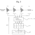
- Fig. 1 is a block diagram of the structure of a position transducer 10 in a first embodiment of the present invention.
- the position transducer 10 is made up of a position indicator 30, a loop coil switching section 40, a signal sensing section 50, a control section 70, a signal generation section 80, a processing section 90, an interface section 100, and a host computer 110.
- the sensor section 20 is made from an electrically conductive material and is provided on a substrate by the use of, for example, pattern deposition, etching or screen printing.
- the loop coils 22 are arranged only in one direction in Fig. 1, it will be possible to calculate coordinates in two axes by providing two sets of the loop coils, arranged side by side, along X and Y axes in such a way that these two sets of the loop coils cross at right angles.
- the loop coil switching section 40 selects each of the loop coils 22, and switches the loop coil between a transmission state and a receiving state. Timing of the selection and switching action is controlled by the control section 70 base on an instruction from the processing section 90.
- the position indicator 30 is a so-called cursor or an input pen.
- An electromagnetic coupling means such as a coil or a capacitor is integrally incorporated in a housing, which permits electromagnetic coupling of the position indicator 30 with the loop coil 22. If a switching mechanism is additionally provided, it will be possible to detect a position selected by the position indicator by varying an electromagnetic coupling frequency when the switch is turned on.
- the position transducer 10 is constructed in such a way that a signal for bringing about electromagnetic interaction is sent from the loop coil, and hence the position transducer 10 is provided with the signal generation section 80.
- the signal generation section 80 generates and outputs an A.C. signal having an arbitrary frequency and phase by utilization of, for example, a random access memory (RAM) or a read only memory (ROM) which stores A.C. signal data, a digital-to-analog (DA) converter, and a low pass filter.
- RAM random access memory
- ROM read only memory
- DA digital-to-analog
- the signal sensing section 50 causes a signal received from the loop coil 22 to be subjected to predetermined processing, and an amplitude and a phase angle of an object frequency component are calculated.
- the processing of the received signal comprises the steps of appropriately adjusting the level of the received signal in a pre-amplifier 52, and effecting phase detection in a phase detection section 54.
- a method utilizing analog phase detection Japanese Patent Publn. No. Hei-2(1990)-53805
- a method utilizing Fourier transformation Japanese Patent Publn. No. Hei-3(1991)-147012
- Both methods obtain a real part (Re) and an imaginary part (Im) of an object frequency component included in a received signal.
- a signal level V and a phase angle ⁇ of an object frequency component are calculated in a computation circuit 56 by the use of the real part and the imaginary part.
- the signal level is calculated from (Re2 + Im2) 1/2
- the phase angle ⁇ is calculated from arctan(Im/Re).
- an amplitude is evaluated as a value obtained from Re2 + Im2, i.e., an amplitude energy value.
- a noise level is eliminated from the signal level V calculated by the computation circuit 56, and a resulting signal is further subjected to processing to obtain a pure amplitude level Vo using a memory element 58 and a subtraction means 60.
- a noise component is treated not as a noise level but as noise energy.
- the amplitude and the noise are represented as a level (voltage) in the subsequent description, these can also be expressed as energy. This noise elimination mechanism will be described later.
- the processing section 90 executes the computation of coordinates based on the data as well as executing general control of data transmission between the processing section 90 and the host computer 110, and each part of the position transducer 10.
- the control section 70 operates based on an instruction from the processing section 90 and controls timing of each part of the position transducer in accordance with a previously set sequence.
- the interface 100 executes the input and output of data to and from the host computer 110.
- the processing section 90 sends the signal generation section 80 an instruction for transmitting a sine wave having a predetermined frequency fo, for example, 500 kHz for a predetermined period, for example, 32 ⁇ S. Meanwhile, the processing section 90 sends the control section 70 switching data for switching a loop coil. As a result of this, the control section 70 executes the switching of the loop coil switching section 40, and the transmission and receipt of a signal. At this time, if the position indicator 30 is situated on the selected loop coil, a received signal will include a signal developed as a result of electromagnetic interaction.
- the signal sensing section 50 processes the received signal, and data representing an amplitude level and a phase angle of a 500 kHz component in the received signal are transmitted to the processing section 90.
- Loop coils which select the previously mentioned operations are sequentially switched, and the above operations are repeated, whereby an amplitude level data pattern is obtained.
- the processing section 90 sends the interface section 100 a result, obtained as result of computation of coordinates of that position, together with phase data.
- the host computer 110 reads these data by accessing the interface 100.
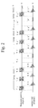
- Fig. 2 shows waveforms of a transmission signal to, and a received signal from, the loop coil in the first embodiment shown in Fig. 1.
- the horizontal axis of the diagram shows time.
- the period designated by a loop coil 1 represents a transmission signal to, and a received signal from, a selected loop coil 1.
- the period designated by a loop coil 2 represents a transmission signal to, and a received signal from, another selected loop coil 2.
- the loop coil 1 is selected, the loop coil 1 is switched to a transmission state, and a signal T1 (f0) is sent.
- this transmission period is, for example, 32 ⁇ s.
- the loop coil 1 is then switched to a receiving state, and the loop coil 1 receives a signal S1.
- a received signal as shown in the drawing, is produced.
- transmission to one loop coil is repeated several times as shown in the drawing, whereby received signals S1, S2, S3 are obtained.
- the accuracy of sensing is improved by averaging these received signals.
- the number of repetitions is represented as being three times in the drawing.
- the transmission and receiving sequences are sequentially executed for all of the loop coils by switching the loop coils.
- periods for example, the periods designated by T4 and T4' in Fig. 2 during which transmission is possible but is interrupted, are provided in the transmission sequence for one loop coil.
- Received signals N and N' corresponding to the transmission interruption periods are received in the same manner as the received signals S1 through S3, and the received signals S1' through S3'.
- only one transmission interruption period is provided in Fig. 2, it is possible to measure a noise signal several times and average the measured values in order to improve noise signal data.
- the received signals S1 through S3 include noise signals arising from various noise sources in addition to the previously mentioned signal, developed only as a result of electromagnetic interaction between the position indicator 30 and the loop coil.
- the received signal N corresponding to the transmission interruption period, does not include the signal developed as a result of electromagnetic interaction but includes solely a noise signal.
- the noise signal N is observed at a very small interval of time just subsequent to the received signals S1 through S3. It is possible to regard the noise signal as having substantially the same level as the noise component included in the received signals S1 through S3.
- Fig. 3 is an explanatory view illustrating the processing of a signal obtained from one loop coil in the first embodiment shown in Fig. 1.
- the waveform of the received signal shown in Fig. 3 is a part of the enlarged signal received from the loop coil 1 shown in Fig. 2.
- Fig. 3 shows a noise component included in the received signals S1 through S3.
- Reference symbol N designates a noise signal including solely a noise component.
- the thus obtained signal level data V1 through V3 and the noise level V N are temporarily stored in the memory element 58.
- a RAM can be used as this memory element 58.
- subtraction is performed in the subtraction means 60 by the use of the data stored in the memory element 58.
- the first term (V1 + V2 + V3) / 3 is ordinary processing for obtaining an average value of the received signal. This average value is taken as a measured signal level.
- a noise component in the signal level is eliminated by subtracting the noise level V N from the signal level, whereby it is possible to obtain a pure amplitude level Vo.
- the first embodiment shown in Fig. 1 it is possible to cope with noise conditions which vary continuously. Moreover, by virtue of this subtraction means, it is possible to eliminate all of the noise components irrespective of the frequency of noise.
- the subtraction means 60 may be constituted in the form of either hardware or software.
- Data representing the amplitude level V0 and being obtained as result of the subtraction, are transmitted to the processing section 90 together with the phase angle data.
- Figs. 4A and 4B are schematic representations showing the structure of the signal sensing section 50 in a second embodiment of the present invention.
- a second memory element 200 is provided for previously storing data representing a noise level in the manner as shown in Fig. 4A.
- a response corresponding to the transmission interruption is received for all of the loop coils prior to the initiation of transmission to the loop coils.
- the noise signal N corresponding to the signal T4 shown in Fig. 2 is previously received for each loop coil, and the received signal is subjected to signal processing by the elements 52 to 56.
- a set of noise levels consisting of noise levels respectively corresponding to the loop coils, are stored into the second memory element 200 (designated by a broken line 300).
- Fig. 4B is a schematic representation showing contents stored in the second memory element 200.
- V N1 , V N2 , V N3 , ... V Nn designate data representing a previously measured noise level of each loop coil.
- a ROM, an EPROM, an EEPROM, or the like, may be used as the second memory element.
- noise environments vary continuously depending on conditions of the use of a system. For example, the actuation of a hard disk drive unit or the turn-on/turn-off of a back light of an LCD cause the noise environments to vary.
- Fig. 5 shows a second memory element 202 in another embodiment which is further provided with a means capable of coping with variations in noise environments.
- the second memory element 202 shown in Fig. 5 consists of a plurality of memory blocks A, B, C, ..., where one memory block corresponds to the second memory element 200 shown in Figs. 4A and 4B.
- a set of data, consisting of noise levels of respective loop coils for any one of a plurality of different noise environments, are stored in each memory block. This provides a plurality of sets of noise levels with respect to a plurality of noise environments. These sets of noise level data stored in the memory blocks are all data which were previously measured prior to position sensing.
- the noise level data may be data measured during a step of assembling the position transducer, or may be data measured in accordance with conditions of a system when the use of the position transducer is initiated together with the system.
- a new noise source is added, it is possible to add a new memory block so as to cope with the environment having that noise source.
- Fig. 6 shows a flow of operations in the system of the position transducer equipped with the second memory element 202 shown in Fig. 5.
- Step 500 shows sets of noise level data, each corresponding to each noise environment, previously stored in respective memory blocks.
- a noise environment is sensed in step 502. The sensing of the noise environment is carried out on the basis of switching associated with, for example, a hard disk drive unit and a power source of a back light for an LCD.
- a memory block corresponding to the sensed noise environment is selected.
- position sensing is effected, and the elimination of a noise component is carried out by the use of the selected memory block.
- the use of the second memory element 202 shown in Fig. 5 makes it possible to facilitate the transmission operation, to reduce a measuring time, and to cope with variations in noise environments.
- the present invention can be effectively applied to a position transducer in which a signal is transmitted from a loop coil, as well as to a position transducer in which a signal is transmitted from the position indicator and received by a loop coil.
- the present invention is also applicable to a position transducer in which position detection is effected by utilization of an oscillation signal resulting from electromagnetic coupling between a loop coil and a position indicator.
Landscapes
- Engineering & Computer Science (AREA)
- General Engineering & Computer Science (AREA)
- Theoretical Computer Science (AREA)
- Physics & Mathematics (AREA)
- Human Computer Interaction (AREA)
- General Physics & Mathematics (AREA)
- Electromagnetism (AREA)
- Measurement Of Length, Angles, Or The Like Using Electric Or Magnetic Means (AREA)
- User Interface Of Digital Computer (AREA)
Applications Claiming Priority (2)
| Application Number | Priority Date | Filing Date | Title |
|---|---|---|---|
| JP125758/94 | 1994-05-16 | ||
| JP12575894A JPH07311647A (ja) | 1994-05-16 | 1994-05-16 | 位置検出装置及びそのノイズ除去方法 |
Publications (2)
| Publication Number | Publication Date |
|---|---|
| EP0684580A2 true EP0684580A2 (de) | 1995-11-29 |
| EP0684580A3 EP0684580A3 (de) | 1996-07-31 |
Family
ID=14918096
Family Applications (1)
| Application Number | Title | Priority Date | Filing Date |
|---|---|---|---|
| EP95303051A Withdrawn EP0684580A3 (de) | 1994-05-16 | 1995-05-04 | Positionssensor und Verfahren zur Rauschunterdrückung. |
Country Status (3)
| Country | Link |
|---|---|
| US (1) | US5691512A (de) |
| EP (1) | EP0684580A3 (de) |
| JP (1) | JPH07311647A (de) |
Cited By (15)
| Publication number | Priority date | Publication date | Assignee | Title |
|---|---|---|---|---|
| WO2010036649A3 (en) * | 2008-09-26 | 2011-04-07 | Apple Inc. | Differential sensing for a touch panel |
| US7995036B2 (en) | 2004-02-27 | 2011-08-09 | N-Trig Ltd. | Noise reduction in digitizer system |
| US8614690B2 (en) | 2008-09-26 | 2013-12-24 | Apple Inc. | Touch sensor panel using dummy ground conductors |
| EP1288849B1 (de) * | 2001-08-24 | 2014-11-19 | Wacom Co., Ltd | Positionsgeber |
| EP2752739A4 (de) * | 2011-08-30 | 2015-06-03 | Nlt Technologies Ltd | Elektronische vorrichtung, elektrostatischer kapazitätssensor und berührungsbildschirm |
| US9164620B2 (en) | 2010-06-07 | 2015-10-20 | Apple Inc. | Touch sensing error compensation |
| EP2669772A3 (de) * | 2012-05-29 | 2016-06-29 | Elo Touch Solutions, Inc. | Projizierte kapazitive Berührungssensorschaltung |
| EP2597552A4 (de) * | 2010-07-21 | 2017-04-12 | Beijing Irtouch Systems Co., Ltd. | Touchscreen und mehrkanal-abtastverfahren dafür |
| US9823774B2 (en) | 2016-02-23 | 2017-11-21 | Microsoft Technology Licensing, Llc | Noise reduction in a digitizer system |
| US10095361B2 (en) | 2015-03-18 | 2018-10-09 | Microsoft Technology Licensing, Llc | Stylus detection with capacitive based digitizer sensor |
| US10296146B2 (en) | 2015-12-22 | 2019-05-21 | Microsoft Technology Licensing, Llc | System and method for detecting grip of a touch enabled device |
| US10423268B2 (en) | 2015-12-22 | 2019-09-24 | Microsoft Technology Licensing, Llc | System and method for detecting grounding state of a touch enabled computing device |
| US10616349B2 (en) | 2018-05-01 | 2020-04-07 | Microsoft Technology Licensing, Llc | Hybrid sensor centric recommendation engine |
| US10678348B2 (en) | 2018-03-12 | 2020-06-09 | Microsoft Technology Licensing, Llc | Touch detection on an ungrounded pen enabled device |
| DE112021004860B4 (de) | 2021-07-29 | 2024-06-06 | Wacom Co., Ltd. | Verfahren zum erfassen eines stiftsignals, sensorsteuerung und system zur positionserfassung |
Families Citing this family (25)
| Publication number | Priority date | Publication date | Assignee | Title |
|---|---|---|---|---|
| JP4510892B2 (ja) * | 2004-09-24 | 2010-07-28 | 株式会社ワコム | ポジションセンサを備える電子デバイス |
| JP4346572B2 (ja) * | 2005-03-23 | 2009-10-21 | 富士通株式会社 | タッチパネル装置におけるノイズ除去のための制御方法および装置並びにタッチパネル装置 |
| US9201556B2 (en) | 2006-11-08 | 2015-12-01 | 3M Innovative Properties Company | Touch location sensing system and method employing sensor data fitting to a predefined curve |
| US8207944B2 (en) | 2006-12-19 | 2012-06-26 | 3M Innovative Properties Company | Capacitance measuring circuit and method |
| US7956851B2 (en) | 2006-12-20 | 2011-06-07 | 3M Innovative Properties Company | Self-tuning drive source employing input impedance phase detection |
| US8243049B2 (en) | 2006-12-20 | 2012-08-14 | 3M Innovative Properties Company | Untethered stylus employing low current power converter |
| US8134542B2 (en) | 2006-12-20 | 2012-03-13 | 3M Innovative Properties Company | Untethered stylus employing separate communication and power channels |
| US8040329B2 (en) | 2006-12-20 | 2011-10-18 | 3M Innovative Properties Company | Frequency control circuit for tuning a resonant circuit of an untethered device |
| US8040330B2 (en) | 2006-12-28 | 2011-10-18 | 3M Innovative Properties Company | Untethered stylus empolying multiple reference frequency communication |
| US7787259B2 (en) | 2006-12-28 | 2010-08-31 | 3M Innovative Properties Company | Magnetic shield for use in a location sensing system |
| US8089474B2 (en) | 2006-12-28 | 2012-01-03 | 3M Innovative Properties Company | Location sensing system and method employing adaptive drive signal adjustment |
| US7812827B2 (en) | 2007-01-03 | 2010-10-12 | Apple Inc. | Simultaneous sensing arrangement |
| US20090009483A1 (en) * | 2007-06-13 | 2009-01-08 | Apple Inc. | Single-chip touch controller with integrated drive system |
| US8493331B2 (en) * | 2007-06-13 | 2013-07-23 | Apple Inc. | Touch detection using multiple simultaneous frequencies |
| US7876311B2 (en) * | 2007-06-13 | 2011-01-25 | Apple Inc. | Detection of low noise frequencies for multiple frequency sensor panel stimulation |
| US9036650B2 (en) * | 2009-09-11 | 2015-05-19 | Apple Inc. | Automatic low noise frequency selection |
| KR101603101B1 (ko) * | 2009-10-23 | 2016-03-14 | 삼성전자 주식회사 | 디스플레이 장치 및 디스플레이 장치의 제어 방법 |
| JP5496735B2 (ja) * | 2010-03-30 | 2014-05-21 | 株式会社ワコム | 指示体位置検出装置及び指示体位置検出方法 |
| KR102004329B1 (ko) * | 2012-05-11 | 2019-07-26 | 삼성전자주식회사 | 좌표 표시 장치 및 좌표 표시 장치의 입력 위치를 측정하는 좌표 측정 장치 |
| WO2014057569A1 (ja) * | 2012-10-12 | 2014-04-17 | Nltテクノロジー株式会社 | 電子機器、静電容量センサ及びタッチパネル |
| WO2014083563A2 (en) | 2012-11-27 | 2014-06-05 | N-Trig Ltd. | Detection with a capacitive based digitizer sensor |
| US10067575B2 (en) * | 2012-11-30 | 2018-09-04 | Apple Inc. | Noise correction for stylus applications on tablets and other touch devices |
| JP6117443B2 (ja) * | 2014-06-30 | 2017-04-19 | シャープ株式会社 | タッチパネルシステム及び電子機器 |
| JP6296307B2 (ja) * | 2016-10-06 | 2018-03-20 | Tianma Japan株式会社 | 電子機器、静電容量センサ及びタッチパネル |
| CN112328129B (zh) * | 2020-11-05 | 2023-07-18 | 深圳市绘王动漫科技有限公司 | 识别干扰的电磁输入装置及电磁输入方法 |
Family Cites Families (10)
| Publication number | Priority date | Publication date | Assignee | Title |
|---|---|---|---|---|
| US4736073A (en) * | 1986-02-10 | 1988-04-05 | Sanders Associates, Inc. | Noise-canceling system for a digitizing tablet |
| JPS6370326A (ja) * | 1986-09-12 | 1988-03-30 | Wacom Co Ltd | 位置検出装置 |
| US4837716A (en) * | 1987-07-24 | 1989-06-06 | Chia Hui Lin | Twin-rate charging and discharging proportional type cursor position determining device |
| US4859814A (en) * | 1988-08-29 | 1989-08-22 | Kurta Corporation | Noise cancellation in digitizing system and method |
| JP2971488B2 (ja) * | 1989-11-01 | 1999-11-08 | 株式会社ワコム | 位置検出装置 |
| US5410750A (en) * | 1992-02-24 | 1995-04-25 | Raytheon Company | Interference suppressor for a radio receiver |
| JP2796606B2 (ja) * | 1992-03-02 | 1998-09-10 | セイコーインスツルメンツ株式会社 | 位置入力装置 |
| EP0843278B1 (de) * | 1992-05-22 | 2002-10-23 | Sharp Kabushiki Kaisha | Tafel mit integrierter Anzeige |
| US5365253A (en) * | 1992-11-12 | 1994-11-15 | Wintime Technology Inc. | Digitizer device with anti-noise and status display |
| US5359156A (en) * | 1992-11-18 | 1994-10-25 | Tritech Microelectronics International Pte Ltd | Integrated circuit for digitizer table with dedicated digital signal processor for improved noise immunity |
-
1994
- 1994-05-16 JP JP12575894A patent/JPH07311647A/ja active Pending
-
1995
- 1995-05-03 US US08/434,297 patent/US5691512A/en not_active Expired - Fee Related
- 1995-05-04 EP EP95303051A patent/EP0684580A3/de not_active Withdrawn
Cited By (21)
| Publication number | Priority date | Publication date | Assignee | Title |
|---|---|---|---|---|
| EP1288849B1 (de) * | 2001-08-24 | 2014-11-19 | Wacom Co., Ltd | Positionsgeber |
| US7995036B2 (en) | 2004-02-27 | 2011-08-09 | N-Trig Ltd. | Noise reduction in digitizer system |
| US8648830B2 (en) | 2004-02-27 | 2014-02-11 | N-Trig Ltd. | Noise reduction in digitizer system |
| US9164618B2 (en) | 2004-02-27 | 2015-10-20 | Microsoft Technology Licensing, Llc | Noise reduction in digitizer system |
| US9372575B2 (en) | 2004-02-27 | 2016-06-21 | Microsoft Technology Licensing, Llc | Noise reduction in digitizer system |
| US9927924B2 (en) | 2008-09-26 | 2018-03-27 | Apple Inc. | Differential sensing for a touch panel |
| US8614690B2 (en) | 2008-09-26 | 2013-12-24 | Apple Inc. | Touch sensor panel using dummy ground conductors |
| WO2010036649A3 (en) * | 2008-09-26 | 2011-04-07 | Apple Inc. | Differential sensing for a touch panel |
| US9164620B2 (en) | 2010-06-07 | 2015-10-20 | Apple Inc. | Touch sensing error compensation |
| US10185443B2 (en) | 2010-06-07 | 2019-01-22 | Apple Inc. | Touch sensing error compensation |
| EP2597552A4 (de) * | 2010-07-21 | 2017-04-12 | Beijing Irtouch Systems Co., Ltd. | Touchscreen und mehrkanal-abtastverfahren dafür |
| EP2752739A4 (de) * | 2011-08-30 | 2015-06-03 | Nlt Technologies Ltd | Elektronische vorrichtung, elektrostatischer kapazitätssensor und berührungsbildschirm |
| EP2669772A3 (de) * | 2012-05-29 | 2016-06-29 | Elo Touch Solutions, Inc. | Projizierte kapazitive Berührungssensorschaltung |
| US10095361B2 (en) | 2015-03-18 | 2018-10-09 | Microsoft Technology Licensing, Llc | Stylus detection with capacitive based digitizer sensor |
| US10296146B2 (en) | 2015-12-22 | 2019-05-21 | Microsoft Technology Licensing, Llc | System and method for detecting grip of a touch enabled device |
| US10423268B2 (en) | 2015-12-22 | 2019-09-24 | Microsoft Technology Licensing, Llc | System and method for detecting grounding state of a touch enabled computing device |
| US9823774B2 (en) | 2016-02-23 | 2017-11-21 | Microsoft Technology Licensing, Llc | Noise reduction in a digitizer system |
| US10678348B2 (en) | 2018-03-12 | 2020-06-09 | Microsoft Technology Licensing, Llc | Touch detection on an ungrounded pen enabled device |
| US10616349B2 (en) | 2018-05-01 | 2020-04-07 | Microsoft Technology Licensing, Llc | Hybrid sensor centric recommendation engine |
| DE112021004860B4 (de) | 2021-07-29 | 2024-06-06 | Wacom Co., Ltd. | Verfahren zum erfassen eines stiftsignals, sensorsteuerung und system zur positionserfassung |
| US12013991B2 (en) | 2021-07-29 | 2024-06-18 | Wacom Co., Ltd. | Detection method of pen signal, sensor controller, and position detection system |
Also Published As
| Publication number | Publication date |
|---|---|
| EP0684580A3 (de) | 1996-07-31 |
| JPH07311647A (ja) | 1995-11-28 |
| US5691512A (en) | 1997-11-25 |
Similar Documents
| Publication | Publication Date | Title |
|---|---|---|
| US5691512A (en) | Position transducer, and method for eliminating noise therefrom | |
| JP2730018B2 (ja) | ディジタイザおよび位置検出方法 | |
| US4848496A (en) | Coordinates input apparatus | |
| US5682019A (en) | Position detecting apparatus and position pointing device including elapsed time period build up detector | |
| US5748110A (en) | Angular input information system relative to a tablet for determining an incline angle of a pointer or stylus | |
| US5862049A (en) | Coordinate input apparatus and control method therefor | |
| JP3517449B2 (ja) | 位置検出方法及びその装置 | |
| US5646377A (en) | Point detecting device and method of same | |
| EP1288849B1 (de) | Positionsgeber | |
| US5530210A (en) | Coordinate detecting device | |
| EP0565852A1 (de) | Optimale Abtastsequenz für RF magnetische Digitalisiergeräte | |
| JP4330513B2 (ja) | 位置検出装置 | |
| JP4117751B2 (ja) | デジタイザ及び位置指示器情報検出方法 | |
| EP0743612B1 (de) | Koordinatenerkennungsgerät und Informationserkennungsverfahren | |
| US5235142A (en) | Phase reference system for cordless looping digitizer | |
| EP0368351B1 (de) | Koordinateneingabegerät | |
| JPS63279315A (ja) | 位置検出装置 | |
| JP3102708B2 (ja) | 位置検出装置 | |
| JP2683819B2 (ja) | コードレスタブレット | |
| JP3409470B2 (ja) | 不要信号除去型座標検出装置 | |
| JPS63257822A (ja) | 位置検出装置 | |
| JPH07113872B2 (ja) | 位置検出装置およびその位置指示器 | |
| JPS63115218A (ja) | 位置検出装置 | |
| JPH03201018A (ja) | 位置検出装置及びそのセンス部 | |
| JPH0816308A (ja) | 超音波座標入力装置 |
Legal Events
| Date | Code | Title | Description |
|---|---|---|---|
| PUAI | Public reference made under article 153(3) epc to a published international application that has entered the european phase |
Free format text: ORIGINAL CODE: 0009012 |
|
| AK | Designated contracting states |
Kind code of ref document: A2 Designated state(s): DE ES FR GB IT PT |
|
| PUAL | Search report despatched |
Free format text: ORIGINAL CODE: 0009013 |
|
| AK | Designated contracting states |
Kind code of ref document: A3 Designated state(s): DE ES FR GB IT PT |
|
| STAA | Information on the status of an ep patent application or granted ep patent |
Free format text: STATUS: THE APPLICATION IS DEEMED TO BE WITHDRAWN |
|
| 18D | Application deemed to be withdrawn |
Effective date: 19970301 |