EP0684613A2 - Halbleitfähiges Polymerelement, Verfahren zur Herstelllung desselben und Vorrichtung damit - Google Patents
Halbleitfähiges Polymerelement, Verfahren zur Herstelllung desselben und Vorrichtung damit Download PDFInfo
- Publication number
- EP0684613A2 EP0684613A2 EP95303674A EP95303674A EP0684613A2 EP 0684613 A2 EP0684613 A2 EP 0684613A2 EP 95303674 A EP95303674 A EP 95303674A EP 95303674 A EP95303674 A EP 95303674A EP 0684613 A2 EP0684613 A2 EP 0684613A2
- Authority
- EP
- European Patent Office
- Prior art keywords
- weight
- electric resistance
- roller
- semiconductive
- temperature
- Prior art date
- Legal status (The legal status is an assumption and is not a legal conclusion. Google has not performed a legal analysis and makes no representation as to the accuracy of the status listed.)
- Withdrawn
Links
Images

Classifications
-
- G—PHYSICS
- G03—PHOTOGRAPHY; CINEMATOGRAPHY; ANALOGOUS TECHNIQUES USING WAVES OTHER THAN OPTICAL WAVES; ELECTROGRAPHY; HOLOGRAPHY
- G03G—ELECTROGRAPHY; ELECTROPHOTOGRAPHY; MAGNETOGRAPHY
- G03G15/00—Apparatus for electrographic processes using a charge pattern
- G03G15/02—Apparatus for electrographic processes using a charge pattern for laying down a uniform charge, e.g. for sensitising; Corona discharge devices
- G03G15/0208—Apparatus for electrographic processes using a charge pattern for laying down a uniform charge, e.g. for sensitising; Corona discharge devices by contact, friction or induction, e.g. liquid charging apparatus
- G03G15/0216—Apparatus for electrographic processes using a charge pattern for laying down a uniform charge, e.g. for sensitising; Corona discharge devices by contact, friction or induction, e.g. liquid charging apparatus by bringing a charging member into contact with the member to be charged, e.g. roller, brush chargers
- G03G15/0233—Structure, details of the charging member, e.g. chemical composition, surface properties
-
- G—PHYSICS
- G03—PHOTOGRAPHY; CINEMATOGRAPHY; ANALOGOUS TECHNIQUES USING WAVES OTHER THAN OPTICAL WAVES; ELECTROGRAPHY; HOLOGRAPHY
- G03G—ELECTROGRAPHY; ELECTROPHOTOGRAPHY; MAGNETOGRAPHY
- G03G15/00—Apparatus for electrographic processes using a charge pattern
- G03G15/06—Apparatus for electrographic processes using a charge pattern for developing
- G03G15/08—Apparatus for electrographic processes using a charge pattern for developing using a solid developer, e.g. powder developer
- G03G15/0806—Apparatus for electrographic processes using a charge pattern for developing using a solid developer, e.g. powder developer on a donor element, e.g. belt, roller
- G03G15/0818—Apparatus for electrographic processes using a charge pattern for developing using a solid developer, e.g. powder developer on a donor element, e.g. belt, roller characterised by the structure of the donor member, e.g. surface properties
-
- G—PHYSICS
- G03—PHOTOGRAPHY; CINEMATOGRAPHY; ANALOGOUS TECHNIQUES USING WAVES OTHER THAN OPTICAL WAVES; ELECTROGRAPHY; HOLOGRAPHY
- G03G—ELECTROGRAPHY; ELECTROPHOTOGRAPHY; MAGNETOGRAPHY
- G03G15/00—Apparatus for electrographic processes using a charge pattern
- G03G15/14—Apparatus for electrographic processes using a charge pattern for transferring a pattern to a second base
- G03G15/16—Apparatus for electrographic processes using a charge pattern for transferring a pattern to a second base of a toner pattern, e.g. a powder pattern, e.g. magnetic transfer
- G03G15/1665—Apparatus for electrographic processes using a charge pattern for transferring a pattern to a second base of a toner pattern, e.g. a powder pattern, e.g. magnetic transfer by introducing the second base in the nip formed by the recording member and at least one transfer member, e.g. in combination with bias or heat
- G03G15/167—Apparatus for electrographic processes using a charge pattern for transferring a pattern to a second base of a toner pattern, e.g. a powder pattern, e.g. magnetic transfer by introducing the second base in the nip formed by the recording member and at least one transfer member, e.g. in combination with bias or heat at least one of the recording member or the transfer member being rotatable during the transfer
- G03G15/1685—Structure, details of the transfer member, e.g. chemical composition
-
- H—ELECTRICITY
- H01—ELECTRIC ELEMENTS
- H01B—CABLES; CONDUCTORS; INSULATORS; SELECTION OF MATERIALS FOR THEIR CONDUCTIVE, INSULATING OR DIELECTRIC PROPERTIES
- H01B1/00—Conductors or conductive bodies characterised by the conductive materials; Selection of materials as conductors
- H01B1/06—Conductors or conductive bodies characterised by the conductive materials; Selection of materials as conductors mainly consisting of other non-metallic substances
- H01B1/12—Conductors or conductive bodies characterised by the conductive materials; Selection of materials as conductors mainly consisting of other non-metallic substances organic substances
- H01B1/121—Charge-transfer complexes
Definitions
- This invention relates to a semiconductive polymer member which is useful in image-forming devices.
- the invention also relates to a method for making such a member as mentioned above and to an image-forming device comprising the same.
- the semiconductive members which have been hitherto used in such fields as set out hereinabove include polymer members wherein powdery or whisker particles of metals or metal oxides are formulated in polymer materials or matrices such as polymeric elastomers or polymeric foams. Alternatively, fillers such as carbon black are incorporated in such materials, so that the resistance of the member is appropriately controlled.
- this type of polymer material has the problems that the electric resistance suffers great positional variations, i.e. it greatly varies depending on the position being measured, and that the electric resistance greatly depends on the measuring voltage.
- polymer members whose resistance is controlled at a predetermined level are known wherein polymer materials such as polymeric elastomers and polymeric foams are formulated with conductive additives and/or antistatic agents such as hydrophilic polyethers or polyesters.
- Such conductive additives include, for example, inorganic ionic substances such as lithium perchlorate, sodium perchlorate and calcium perchlorate and/or organic ionic substances including cationic surface active agents such as lauryltrimethylammonium chloride, stearyltrimethylammonium chloride, octadecyltrimethylammonium chloride, dodecyltrimethylammonium chloride, hexadecyltrimethylammonium chloride, modified aliphatic group/dimethylethylammonium ethosulfate and the like, amphoteric surface active agents such as lauryl betaine, stearyl betaine, dimethylalkyllauryl betaine and the like, and quaternary ammonium salts such as tetraethylammonium perchlorate, tetrabutylammonium perchlorate, tetrabutylammonium borofluoride and the like.
- This type of polymeric member has
- the polymer member should have a low hardness in order to obtain high-quality images.
- the low hardness requirement of the polymer member is usually achieved according to several methods. Such methods include, for example, a method wherein foams are incorporated in the member to provide a foamed body, a method wherein the amount of carbon black used as a reinforcing material is reduced or a member is altered as having a low grade of reinforcement, and a method wherein plasticizers such as oils are added.
- disadvantages are involved in the method for making the foamed body, the use of a reinforcing material in reduced amounts or the alteration in type of a reinforcing material in that the resultant member lowers in breaking force.
- This type of member is ordinarily used in a condition where it is applied with a load of not less than 500 g. Accordingly, when the breaking force is lower than 2.2 kgf/cm2, the member will become broken in a long-term use. Especially, when the tensile of breakage is below 2 kgf/cm2, a frequency of breakage undesirably increases.
- the general aim herein is to provide new and useful conductive polymeric materials, members made from them and methods of preparing them.
- roller for use in electrophotography which comprises a semiconductive polymer member whereby the prior art disadvantages involved in ordinarily employed rollers in the field of electrophotography can be overcome.
- a useful semiconductive polymer member is obtained from the polymer material in which the acceptor is included. It may for example show a volume electrical resistance which ranges from 1 x 10⁵ ⁇ cm to 1 x 10¹⁰ ⁇ cm when measured under conditions of a temperature of from 15 to 32.5°C, a relative humidity of from 10 to 85% and a measuring potential of from 10 to 5000 V.
- the polymer member may have low positional variation in the electric resistance and/or low width of variations in the electric resistance as determined under low temperature and low humidity conditions and under high temperature and high humidity conditions.
- a semiconductive polymer member which is made of a semiconductive polymer composition which comprises a polymer matrix and preferably further at least one member selected from the group consisting of electron acceptors capable of forming charge transfer complexes and charge transfer complexes, and which has an electric resistance ranging from 1 x 10⁵ ⁇ cm to 1 x 10¹⁰ ⁇ cm when measured under conditions of a temperature of from 15 to 32.5°C, a relative humidity of from 10 to 85% and a measuring potential of from 10 to 5000 V and has a positional variation in the electric resistance of not larger than ⁇ 20%, and wherein an electric resistance determined under conditions of a temperature of 15°C and a relative humidity of 10% is not larger than 50 times an electric resistance determined under conditions of a temperature of 32.5°C and a relative humidity of 85%.
- a semiconductive polymer member made of a polymer material obtained by reaction between a polyol component and an isocyanate component and shaping the polymer material in a given form, an electron acceptor capable of forming a charge transfer complex is added to the isocyanate component as a conductivity-imparting agent to obtain a semi-conductive polymer composition which has such an electric resistance that a volume resistance ranges from 1 x 10⁵ ⁇ ⁇ cm to 1 x 10¹⁰ ⁇ ⁇ cm when determined under conditions of a temperature of 15 to 32.5°C and a relative humidity of 10 to 85% at a measuring potential of 10 to 5000 V.
- the semiconductive polymer member has a reduced positional variation in the electric resistance and a reduced width of variations in the electric resistance as determined under low temperature and low humidity conditions and under high temperature and high humidity conditions.
- a method for preparing a semiconductive polymer member which comprises providing a polyurethane-preparing composition containing a polyol component, an isocyanate component and a conductivity-imparting agent and reacting the polyol component and the isocyanate component, characterized in that the conductivity-imparting agent consists of an electron acceptor capable of forming a charge transfer complex and that the electron acceptor is added by dissolution in the isocyanate component.
- the semiconductive polymer when the polyol is used in the form of a prepolymer and the polyurethane-preparing composition is foamed according to a mechanical frothing method, the semiconductive polymer can be effective prepared.
- a method for preparing a semiconductive polymer member which comprises providing a polyurethane-preparing composition containing a polyol component, an isocyanate component and a conductivity-imparting agent and reacting the polyol component and the isocyanate component, wherein the conductivity-imparting agent consists of an electron acceptor capable of forming a charge transfer complex, the polyol is prepolymerized, and the composition is foamed according a mechanical frothing method and is subjected to the reaction.
- a power supply used for this purpose is effectively one which is able to detect environmental conditions and/or a load resistance and control power conditions.
- a power source includes, for example, a power source for transfer devices, a constant current power supply or a constant voltage power supply.
- a transfer device which comprises means including a semiconductive member which is made of a semiconductive polymer composition comprising a polymer matrix and an electron acceptor capable of forming a charge transfer complex and/or a charge transfer complex and to which a bias voltage is applicable, and a power supply for transfer devices associated with the means to detect environmental conditions and/or a load resistance of the means thereby appropriately controlling power supply conditions applied to the means.
- a device which comprises means including a semiconductive member which is made of a semiconductive polymer composition comprising a polymer matrix andan electron acceptor capable of forming a charge transfer complex and/or a charge transfer complex and to which a bias voltage is applicable, and a constant current power supply associated with the means.
- a device which comprises means including a semiconductive member which is made of a semiconductive polymer composition comprising a polymer matrix and an electron acceptor capable of forming a charge transfer complex and/or a charge transfer complex and to which a bias voltage is applicable, and a constant voltage power supply associated with the means.
- a semiconductive polymer member is made of a polymer material to which a conductivity-imparting agent is added.
- the member has such an electric resistance that its volume resistance ranges from 1 x 10⁵ ⁇ cm to 1 x 10¹⁰ ⁇ cm when determined under conditions of a temperature of 15 to 32.5°C and a relative humidity of 10 to 85% at a measuring potential of 10 to 5000 V.
- the positional variation in the electric resistance is within ⁇ 20%, preferably within ⁇ 10% and the electric resistance under low temperature and low humidity conditions of 15°C and 10% is not higher than 50 times, preferably not higher than 40 times, that determined under high temperature and high humidity conditions of 32.5°C and 85%.
- polymer material examples include resins such as polyethylene, polypropylene, polyurethane and the like, natural rubber, and synthetic rubbers such as butadiene rubber, styrene-butadiene rubber, isoprene rubber, EPDM (ethylene- propylene- dienomethylene rubber), NBR (nitril-butadiene rubber) and the like.
- resins such as polyethylene, polypropylene, polyurethane and the like
- natural rubber such as butadiene rubber, styrene-butadiene rubber, isoprene rubber, EPDM (ethylene- propylene- dienomethylene rubber), NBR (nitril-butadiene rubber) and the like.
- EPDM ethylene- propylene- dienomethylene rubber
- NBR nitril-butadiene rubber
- the foaming method is not critical.
- foaming agents are employed for rubber members and a method wherein foaming agents are used or foams are incorporated by mechanical agitation especially for urethane members.
- the method using the mechanical agitation is called a mechanical frothing method.
- the method for making rubber members is not critical.
- a rubber material is mixed with conductive materials (i.e, conductivity-imparting agents), crosslinking agents such as sulfur, peroxides and the like, reinforcing agents such as carbon black, antioxidants, crosslinking reaction promoters and the like, followed by thermal curing.
- the method for making a urethane member is not critical as well.
- chain propagating agents and curing agents with the above-mentioned conductivity-imparting agents, reinforcing agents such as carbon black, catalysts for crosslinkage and the like, followed by thermal curing.
- the propagating agent include polyether polyols, polyester polyols, polybutadiene polyols, polyisoprene polyols, polyols obtained by addition polymerization between glycerine and polyethylene oxide or polypropylene oxide, ethylene glycol, propanediol, butanediol and the like.
- curing agent examples include tolylene diisocyanate (TDI), liquid MDI compounds such as diphenylmethane diisocyanate (MDI), crude diphenylmethane diisocyanate (crude MDI), urethoneimine - modified phenylmethane diisocyanate and the like, and isophorone diisocyanate.
- TDI tolylene diisocyanate
- MDI diphenylmethane diisocyanate
- CAde MDI crude diphenylmethane diisocyanate
- urethoneimine - modified phenylmethane diisocyanate and the like examples of the curing agent.
- isophorone diisocyanate The ratio by equivalence between the isocyanate component and the polyol component is in the range of 0.8:1 to 1.5:1, preferably 1:1 to 1.2:1.
- the curing agent used for the urethane foams is not tolylene diisocyanate, but a liquid MDI compound such as crude diphenylmethane diisocyanate (crude MDI), urethaneimine-modified diphenylmethane diisocyanate, carbodiimide-modified diphenylmethane diisocyanate, urethone-modified diphenylmethane diisocyanate and/or hydrogenated products thereof, a stain resistance against photosensitive materials can significantly lower.
- the crude diphenylmethane diisocyanate is preferred in view of the stain resistance against photosensitive material. More preferably, the crude MDI should have at least three functional groups.
- urethane members For the fabrication of urethane members, it is preferred to use a mold having a given dimension. By this, a smooth surface layer (so-called self skin and/or integral skin) is formed.
- self skin means a very thin film formed in the following manner: when a material is poured into a mold made of a metal or other material and is set therein, a very thin film is invariably formed at portions contacting the mold.
- the skin is usually very thin and has, at most, a thickness of 1 to 800 ⁇ m.
- the skin has substantially the same physical properties such as a density, strength and the like, as the inside material.
- this skin differs from a so-called integral skin foam which is formed by use of a specific type of integral foaming formulation in the preparation of urethanes or by controlling molding conditions, under which while a urethane reaction is caused to occur, the density or the number of cells are continuously changed between the inside foams and the foams in or on the surfaces, thereby changing physical properties therebetween.
- the self skin foam is lower in hardness than the integral-skin foam.
- the thus fabricated urethane member of the invention having a self-skin layer have the following physical properties. Resistance (both inside and surface side): 1 x 10⁵ to 1 x 10¹⁰ ⁇ cm Average cell size (both inside and surface side): 3 to 300 ⁇ m Density (both inside and surface side): 0.3 to 0.8 g/cm3
- the member may be fabricated as having an integral-skin foam structure or pattern.
- the physical properties at the inside and surface sides may be controlled within the following ranges, respectively. Density: 0.3 to 0.8 g/cm3 for inside foam and 0.6 to 1.1 g/cm3 for surface foam Skin thickness: 0.3 mm to 3 mm as a surface foam Average cell size: 200 to 300 ⁇ m for inside foam and 1 to 100 ⁇ m for surface foam
- a semiconductive polymer member is made of a polymer matrix to which a conductivity-imparting agent is added.
- the conductivity-imparting agent is favorably an electron acceptor capable of forming a charge transfer complex.
- the electron acceptors capable of forming charge transfer complexes include tetracyanoethylene, tetracyanoquinodimethane, benzoquinone, chloroanil, anthraquinone, anthracene, dichlorodicyanobenzoquinone, ferrocene, phthalocyanine and the like.
- derivatives of these compounds are preferably used.
- the compounds or derivatives may be used singly or in combination. Of these, tetracyanoquinodimethane or tetracyanoethylene is preferred.
- the electron acceptor may be used in the form of complexes with electron donors such as tetrathiafluvalene, lithium and the like.
- the electron acceptor is preferably added to the polymer matrix in an amount of 0.001 to 20 parts by weight, preferably from 0.01 to 1 part by weight, per 100 parts by weight of the matrix.
- additives include known conductive fillers such as carbon black, metallic powders, metal oxides and the like, ionic conductive agents including inorganic substances such as lithium perchlorate and organic ionic substances such as quaternary ammonium salts, cationic surface active agents, anionic surface active agents, ampholytic surface active agents such as various types of betaines, and nonionic antistatic agents such as hydrophilic polyethers and polyesters.
- conductive fillers such as carbon black, metallic powders, metal oxides and the like
- ionic conductive agents including inorganic substances such as lithium perchlorate and organic ionic substances such as quaternary ammonium salts, cationic surface active agents, anionic surface active agents, ampholytic surface active agents such as various types of betaines, and nonionic antistatic agents such as hydrophilic polyethers and polyesters.
- ionic conductive agents including inorganic substances such as lithium perchlorate and organic ionic substances such as quaternary ammonium salts, cationic
- the electron acceptors capable of forming charge transfer complexes cannot be added to polyols, but is preferably added after dissolution in isocyanate components including tolylene diisocyanate (TDI), liquid MDI's such as diphenylmethane diisocyanate (MDI), crude diphenylmethane diisocyanate (crude MDI), urethoneimine - modified diphenylmethane diisocyanate and the like, and isophorone diisocyanate.
- TDI tolylene diisocyanate
- MDI diphenylmethane diisocyanate
- CAde MDI crude diphenylmethane diisocyanate
- urethoneimine - modified diphenylmethane diisocyanate and the like isophorone diisocyanate.
- Preferable carbon black includes Ketjen black, acetylene black, oil furnace black, thermal carbon, channel black or the like. More preferably, carbon black should have a DBP absorption of not less than 40 ml/100 g and a surface area of not less than 10 m2/g when measured according to a nitrogen absorption technique and a content of volatile matters of not higher than 10% when heated at 970°C for 7 minutes. This is considered for the reason that when carbon black having such oil absorption and surface area as defined above is formulated, matters to be bled from the polymer matrix are effectively absorbed in the carbon black present therein, not permitting the matters to be bled to the surface of the member. When carbon black having a volatile matter content exceeding the above range, the matter bled from carbon black itself migrates toward the surface of the member.
- the inorganic salts preferably include perchlorates, hydrochlorides, hydroborofluorides and sulfates of alkali metals and/or alkaline earth metals such as lithium, sodium, potassium, calcium and the like.
- quaternary ammonium salts examples include perchlorates, hydrochlorides, hydroborofluorides, sulfates and ethosulfates of quaternary ammoniums such as lauryltrimethylammonium, stearyltrimethylammonium, dodecyltrimethylammonium, hexadecylammonium, modified aliphatic dimethylethylammonium, tetraethylammonium, tetrabutyl-ammonium and the like.
- the electron acceptors capable of forming charge transfer complexes are not critical in type and preferably include tetracyanoethylene and/or derivatives thereof, tetracyanoquinodimethane and/or derivatives thereof, benzoquinone and/or derivatives thereof, anthraquinone and/or derivatives thereof, anthracene and/or derivatives thereof, dichlorodicyanobenzoquinone and/or deriva-tives thereof, ferrocene and/or derivatives thereof, and phthalocyanine and/or derivatives thereof.
- Semiconductive polymer members proposed here are found to exhibit stable variations of electric resistance against a voltage being applied.
- the variation should be not greater than two times, more preferably not greater than 1.2 times, the lowest electric resistance within a certain voltage being applied.
- polymer members which are imparted with electric conductivity by addition of fillers such as carbon black, metallic powders, metal oxides and the like undergo a great variation in electric resistance in relation to the variation in applied voltage. For instance, when the applied voltage is at 10 V, the electric resistance reaches a level as high as five times the electric resistance determined at an applied voltage of 5000 V.
- a semiconductive polymer member as proposed here may have a dependence of the electric resistance on a measuring voltage that the electric resistance measured at 10 V is not greater than two times the electric resistance measured at 5000 V. This is very beneficial when the semiconductive polymer member is applied to image-forming devices used, for example, in electrophotography particularly in the form of rollers of transfer devices and developing devices.
- the semiconductive polymer member of the invention should preferably comprise, as a polymer matrix, a polyurethane foam which has a breaking strength of not lower than 2 kgf/cm2, preferably not lower than 2.2 kgf/cm2, and an Ascar hardness of not larger than 50° , preferably not larger than 42°.
- This polyurethane foam is preferably formed from a prepolymerized polyol wherein the foaming is effected according to a mechanical frothing method.
- Semiconductive polymer members as proposed herein are found to be effective as packing members having an antistatic function, impact absorbing members having an antistatic function, and semiconductive members to be used in electrophotographic processes, e.g. elastic rollers for charging, developing and transferring devices.
- the present invention provides a charging, transferring or developing device which comprises a charging, transferring or developing member comprising a semiconductive member which is made of a polymer matrix and an electron acceptor capable of forming a charge transfer complex and/or a charge transfer complex and which is applicable with a bias voltage, and a power supply for transfer devices for detecting environmental conditions and/or a load resistance to appropriately control power-supplying conditions.
- the power supply may be a constant current power supply or a constant voltage power supply for the reasons as will be described hereinafter.
- the charging, transferring and developing members used, respectively, in charging, transferring and developing devices of the invention make use of the semiconductive polymer member set out hereinbefore and are not critical in shape.
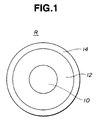
- these members are in the form of a roller having a metal core or shaft at a central portion thereof. This is particularly shown in Fig. 1.
- a roller R includes a metal core 10 positioned at a central portion thereof and a semiconductive polymer member 12 to cover a necessary portion of the core 10 therewith.
- the manner of shaping the roller is not critical. Usual practice is to use a method wherein grind stone is used for polishing or a method which makes use of a mold for an intended shape of roller thereby obtaining a self-skin-bearing foam or elastomer roller.
- the charging, transferring or developing member may further comprise, on the semiconductive polymer member 12, at least one conductive, semiconductive or insulating film layer 14 as is particularly shown in Fig. 1 wherein only one additional layer is depicted.
- the layer 14 is preferably made of nylons (polyamides). More preferably, an interpolyamide or interpolymer-type nylon having not less than 15 wt% of nylon 12 is employed, by which charging and environmental stability is improved.
- the interpolyamide should preferably have a melting point not higher than 120°C, more preferably 70 to 120°C and most preferably 90 to 110°C.
- the film layer is not critical with respect to volume resistivity.
- the volume resistivity is in the range of from 106 to 1013 ⁇ cm.
- at least one of carbon black and metal oxides such as tin oxide, titanium oxide and the like may be added in the form of particles.
- the film layer is formed of a urethane-modified acrylic resin containing from 5 to 70 wt% of an acrylic resin component.
- the acrylic resin component should preferably have a glass transition temperature of from room temperature to 80°C.
- the film layer is not critical with respect to volume resistivity.
- the volume resistivity is preferably in the range of from106 to 1013 ⁇ cm.
- the volume resistivity can be appropriately controlled by adding at least one of carbon black and metal oxides such as tin oxide, titanium oxide and the like in the form of particles. It is also preferred to add from 1 to 50 wt% of a silicone component to the urethane-modified acrylic resin.
- particles having a size of 35 to 100 ⁇ m are provided in the vicinity of the surface of a body to be charged, for example, in an electrophotographic system, thereby reducing noises of the system.
- the particles used are not critical and may be either insulating or conductive in nature. Insulating particles may be each covered with a conductive film or elastic material.
- the particles are not critical in amount and are preferably used in an amount of 3 to 50 parts by weight per 100 parts by weight of a polymer capable of forming the film or elastic material.
- FIG. 2 shows an electrophotographic system E.
- the system E includes a photosensitive drum 1, a charging roller 2, a developing roller 3 and a transfer roller 4 each in contact or association with the photosensitive drum 1 as shown.
- the rollers 2, 3 and 4 are, respectively, connected to one power supply or individual power supplies (not shown), thereby making charging, transferring and developing devices of the invention.
- the drum 1 is uniformly charged with the roller 2 and a latent imagewise pattern is formed on the drum 1 by means of a laser beam 6, followed by development by means of the developing roller 3 in a toner box 7.
- the resultant visible image is transferred to a transfer sheet 5 with the aid of the roller 4.
- the charging, transferring and developing devices proposed here undergo a reduced variation between the electric resistances determined under high temperature and high humidity conditions and under low temperature and low humidity conditions when compared with existing devices comprising a hitherto employed member which is imparted with semiconductivity by addition of inorganic ionic conductive agents.
- the variation attained by the devices of the invention is not suppressed to an extent as attained by devices which are made using a member which is imparted with semiconductivity by addition of carbon black or metal oxide particles.
- the charging, transferring and developing devices proposed here preferably include a power supply capable of detecting environmental conditions (including temperature and humidity) and/or a load resistance to control power supply conditions.
- the load resistance is great and/or under environmental conditions such as of low temperature and low humidity where the load resistance becomes great
- a power supply is so controlled that the voltage becomes high.
- the voltage is controlled within such a range that the voltage of the power supply under low temperature and low humidity conditions and/or at a great load resistance is 2 to 100 times, preferably 5 to 30 times, as great as the voltage under high temperature and high humidity conditions and/or at a small load resistance.
- Another type of power supply which is adapted for use in the charging, transferring and developing devices of the invention may be a constant current power supply. According to our investigations, good-quality images can be obtained when a constant current is applied to the devices of the invention irrespective of a load resistance and/or environmental conditions. Presumably, this is because the quantity of charge depends greatly on the current for the charging device. For the transferring and developing devices, the amount of a transferred toner necessary for the development and transfer is considered to depend on the current.
- the charging, transferring and developing devices proposed here are found to have low variation between the electric resistances under high temperature and high humidity conditions and under low temperature and low humidity conditions than corresponding devices using a member imparted with semiconductivity by use of hitherto employed inorganic ionic conductive agents. Accordingly, a constant voltage power supply may also be used as a power supply for these devices.
- the voltage applicable for this purpose is in the range of not higher than 10 kV, preferably not higher than 4 kV.
- a power supply is preferably one which is able to apply a voltage of reversed polarity capable of compensating not smaller than 60%, preferably not smaller than 80%, of a cumulative ampere or cumulative amount of current at the time of transfer operations at least for a given period of time during non-transfer cycles. More particularly, when the semiconductive member used in the device of the invention is continuously applied with a current, an electron acceptor capable of forming a charge transfer complex and serving as a conductive carrier suffers polarization, resulting in a gradual increase of electric resistance. Thus, it is preferred to apply a de-polarization voltage to the member thereby suppressing the resistance from increasing.
- the power supply or supplies for the charging, transferring and developing devices of the invention are assumed to be a DC power supply, it is preferred to superpose AC currents of a sine wave, a saw tooth wave or a square wave on the power supply. It is also preferred to use an artificial DC power supply using high frequency pulses as a substitute for the DC power supply.
- the current capacity of the power supply for the charging device of the invention is preferably within a range of not higher than 5 mA, more preferably not higher than 1 mA.
- the power capacities of the transferring and developing devices of the invention preferably include a voltage of not higher than 5000 V, more preferably not higher than 2000V and a current of not higher than 1 mA, more preferably not higher than 500 ⁇ A.
- a polyether polyol obtained by addition of propylene oxide and ethylene oxide to glycerine and having a molecular weight of 5000, 6.56 parts by weight of 1,4-butanediol, 22 parts by weight of tolylene diisocyanate, 2 parts by weight of silicone surface active agent, 0.01 part by weight of dibutyltin dilaurate, and 0.01 part by weight of tetracyanoethylene were mixed by means of a hand-operated mixer. The resultant mixture was poured into a 5.5 mm thick flat mold and cured at 60 for 12 hours to obtain a urethane foam sheet.
- the urethane foam sheet was subjected to measurement of electric resistance wherein four circular electrodes each with an area of 19.6 cm2 were, respectively, placed on four points of the sheet and a power supply, 610C of Trek, Inc., was used.
- the temperature and humidity at the measurement were, respectively, 15°C and 10%.
- the electric resistance, as an average of the four measurements, was 1.4 x 10⁹ ⁇ for an applied voltage of 1000 V and 1.3 x 10⁹ ⁇ for an applied voltage of 4000 V.
- the positional variation of the electric resistance was within ⁇ 5% of the average.
- the measuring temperature and humidity were, respectively, 32.5°C and 85%, the electric resistance at an applied voltage of 1000 V was 5.7 x 10⁷ ⁇ as the average of the four measurements.
- Example 2 The general procedure of Example 1 was repeated except that 0.04 parts by weight of a diethylene glycol monomethyl ester solution of 33% sodium perchlorate (NaClO4, molecular weight of 122.5) was used in place of 0.01 part by weight of tetracyanoethylene used as the conductive agent.
- the electric resistance as an average of four measurements, was 2.9 x 10⁸ ⁇ for an applied voltage of 1000 V and 2.7 x 10⁸ ⁇ for a voltage of 4000 V.
- the positional variation of the electric resistance was within a range of ⁇ 5% relative to the average value.
- the electric resistance as an average of four measurements, was 4.6 x 10⁶ ⁇ for an applied voltage of 1000 V.
- the comparison with the example reveals that the urethane foam of this comparative example exhibits a great variation in the electric resistance occurring between low temperature and low humidity conditions and high temperature and high humidity conditions.
- Example 1 The general procedure of Example 1 was repeated except that 0.016 parts by weight of tetracyanoquinodimethane was used in place of 0.01 part by weight of tetracyanoethylene used as the conductive agent.
- the electric resistance as an average of four measurements, was 1.9 x 10⁸ ⁇ for an applied voltage of 1000 V and 1.9 x 10⁸ ⁇ for a voltage of 4000 V.
- the positional variation of the electric resistance was within a range of ⁇ 5% relative to the average value.
- the electric resistance, as average of four measurements was 1.5 x 10⁷ ⁇ for an applied voltage of 1000 V.
- Example 2 The general procedure of Example 1 was repeated except that 1.5 parts by weight of acetylene black was used in place of 0.01 part of tetracyanoethylene used as the conductive agent.
- the electric resistance as an average of four measurements, was 2.9 x 10⁸ ⁇ for an applied voltage of 1000 V and 7.8 x 10⁷ ⁇ for a voltage of 4000 V.
- the positional variation of the electric resistance was within a range of ⁇ 50% or over relative to the average value.
- the measuring temperature and humidity were, respectively, 32.5°C and 85%
- the electric resistance, as an average of four measurements was 3.0 x 10⁸ ⁇ for an applied voltage of 1000 V.
- the urethane foam of this comparative example had a great variation in the electric resistance between the applied voltages of 1000 V and 4000 V.
- a polyether polyol obtained by addition of propylene oxide and ethylene oxide to glycerine and having a molecular weight of 5000, 6.56 parts by weight of 1,4-butanediol, 22 parts by weight of tolylene diisocyanate, 2 parts by weight of silicone surface active agent, 0.01 part by weight of dibutyltin dilaurate, and 0.01 part by weight of tetracyanoethylene were mixed by means of a hand-operated mixer.
- the resultant mixture was used to cover a metallic shaft having a diameter of 6 mm and cured to make a urethane foam transfer roller having a diameter of 16.5 mm and a length of 215 mm.
- This transfer roller was set in an image-forming device of the type as shown in Fig. 2 wherein the roller was used as a transfer roller 4.
- grey scale, black solid and white solid images were, respectively, printed under conditions of a temperature of 15°C and a humidity of 10%, thereby obtaining images of good quality.
- printing of grey scale, black solid and white solid images under conditions of a temperature of 32.5°C and a humidity of 85% resulted in good-quality images.
- an electrophotographic device E includes a photosensitive material or drum 1, and a charging roller 2, a developing roller 3 and a transfer roller 4 provided in contact or association with the photosensitive material 1.
- Indicated by 5 is a transfer material such as ordinary paper
- by 6 is a laser beam for imagewise irradiation of the photosensitive material 1 therewith
- by 7 is a toner box.
- Example 3 The general procedure of Example 3 was repeated except that 0.04 parts by weight of a diethylene glycol monomethyl ester solution of 33% sodium perchlorate (NaClO4, molecular weight of 122.5) was used in place of 0.01 part by weight of tetracyanoethylene used as the conductive agent.
- Grey scale, black solid and white solid images were, respectively, printed under conditions of a temperature of 15°C and a humidity of 10%, thereby obtaining images of good quality.
- grey scale, black solid and white solid images were,respectively, printed under conditions of a temperature of 32.5°C and a humidity of 85%, the resultant black solid image was not satisfactory with respect to blackness.
- a polyether polyol obtained by addition of propylene oxide and ethylene oxide to glycerine and having a molecular weight of 5000, 6.56 parts by weight of 1,4-butanediol, 22 parts by weight of tolylene diisocyanate, 0.01 part by weight of dibutyltin dilaurate, and 0.01 part by weight of tetracyanoethylene were mixed in vacuum by means of a laboratory mixer.
- the resultant mixture was used to cover a metallic shaft having a diameter of 6 mm and cured to make a urethane elastomer developing roller having a diameter of 20 mm and a length of 222 mm.
- This developing roller was set in an image-forming device of the type as shown in Fig. 2.
- grey scale, black solid and white solid images were, respectively, printed under conditions of a temperature of 15°C and a humidity of 10%, thereby obtaining images of good quality.
- printing of grey scale, black solid and white solid images under conditions of a temperature of 32.5°C and a humidity of 85% resulted in good-quality images.
- the semiconductive polymer members of our proposals had a reduced positional variation in the electric resistance and suffers a reduced width of variation in the electric resistance when continuously applied with a current.
- the member when the member is utilized as rollers for development and transfer in electrophotographic processes, good-quality images can be obtained.
- the transfer rollers obtained in Example 3 and Comparative Example 3, respectively, were set in a charging device of an electrophotographic device as shown in Fig. 2 for use as a charging roller. Under conditions of a temperature of 15°C and a humidity of 10%, grey scale, black solid and white solid images were printed, with good-quality images. When grey scale, black solid and white solid images were, respectively, printed under conditions of a temperature of 32.5°C and a humidity of 85% by use of the charging device having the charging roller of the example, the resultant images were good in quality. However, with the device for comparison, printing of grey scale, black solid and white solid images under condition of a temperature of 32.5°C and a humidity of 85% resulted in a black solid image which was not satisfactory with respect to blackness.
- a polyether polyol obtained by addition of propylene oxide and ethylene oxide to glycerine and having a molecular weight of 5000, 6.03 parts by weight of tolylene diisocyanate, 2 parts by weight of a silicone surface active agent, 0.035 parts by weight of dibutyltin dilaurate, and 0.03 parts by weight of tetracyanoethylene were mixed by means of a hand-operated mixer.
- the resultant mixture was used to cover a metallic shaft having a diameter of 6 mm and cured to make a self skinbearing urethane foam developing roller having a diameter of 16.5 mm and a length of 215 mm.
- a film layer made of a mixture of an acrylmodified urethane resin (having 40 wt% of an acrylic resin component) and 20 parts by weight of carbon black (2400B of Mitsubishi Kasei Corporation) was further formed on the urethane foam layer, therby making a charging roller.
- This charging roller was set in an electrophotographic device as shown in Fig. 2.
- grey scale, black solid and white solid images were,respectively, printed undre conditions of a temperature of 15°C and a humidity of 10%, the resultant images were good in quality.
- printing of grey scale, black solid and white solid images under conditions of a temperature of 32.5°C and a humidity of 85% resulted in good-quality images.
- a polyether polyol obtained by addition of propylene oxide and ethylene oxide to glycerine and having a molecular weight of 5000, 6.56 parts by weight of 1,4-butanediol, 22 parts by weight of tolylene diisocyanate in which 0.03 parts by weight of tetracyanoquinodimethane had been preliminarily dissolved, 2 parts by weight of a silicone surface active agent, and 0.01 part by weight of dibutyltin dilaurate were mixed by means of a mixer.
- the resultant mixture was poured into a flat mold having a thickness of 5.5 mm and cured at 60°C for 12 hours to obtain a urethane foam sheet.
- the electric resistance of the urethane foam was measured at four points thereof.
- the measuring temperature and humidity were, respectively, 15°C and 10%.
- the electric resistance, as an average of four measurements was 1.4 x 10⁹ ⁇ for an applied voltage of 1000 V and 1.3 x 10⁹ ⁇ for a voltage of 4000 V.
- the positional variation of the electric resistance was within a range of ⁇ 5% relative to the average value.
- the electric resistance, as an average of four measurements was 5.7 x 10⁷ ⁇ for an applied voltage of 1000 V.
- Example 7 The general procedure of Example 7 was repeated except that tetracyanoquinodimethane was preliminarily dissolved in 1,4-butanediol, but was found to be sparingly soluble in 1,4-butanediol, under which a urethane foam sheet was made.
- the urethane foam sheet was subjected to measurement of an electric resistance at four points of the foam.
- the electric resistance as an average of four measurements, was 1 x 10¹¹ ⁇ for an applied voltage of 1000 V.
- the resultant mixture was poured into a flat mold having a thickness of 5.5 mm and cured at 60°C for 12 hours to obtain a urethane foam sheet.
- the electric resistance of the urethane foam was measured at four points thereof.
- the measuring temperature and humidity were, respectively, 15 and 10%.
- the electric resistance, as an average of four measurements was 1.4 x 10⁹ ⁇ for an applied voltage of 1000 V and 1.3 x 10⁹ ⁇ for a voltage of 4000 V.
- the positional variation of the electric resistance was within a range of ⁇ 5% relative to the average value.
- the electric resistance, as an average of four measurements was 5.7 x 10⁷ ⁇ for an applied voltage of 1000 V.
- a polyether polyol obtained by addition of propylene oxide and ethylene oxide to glycerine and having a molecular weight of 5000
- 9.15 parts by weight of crude diphenylmethane diisocyanate (crude MDI) in which 0.03 parts by weight of 0.03 parts by weight of tetracyanoquinodimethane had been preliminarily dissolved, 2 parts by weight of a silicone surface active agent, and 0.01 part by weight of dibutyltin dilaurate were mixed by means of a mixer.
- the resultant mixture was poured into a flat mold having a thickness of 5.5 mm and cured at 60°C for 12 hours to obtain a urethane foam sheet.
- the electric resistance of the urethane foam was measured at four points thereof.
- the measuring temperature and humidity were, respectively, 15 and 10%.
- the electric resistance, as an average of four measurements was 1.4 x 10⁹ ⁇ for an applied voltage of 1000 V and 1.3 x 10⁹ ⁇ for a voltage of 4000 V.
- the positional variation of the electric resistance was within a range of ⁇ 5% relative to the average value.
- the electric resistance, as an average of four measurements was 5.7 x 10⁷ ⁇ for an applied voltage of 1000 V.
- Example 7 The mixture of such a formulation as used in Example 7 was used to cover a metallic shaft having a diameter of 6 mm to make a urethane foam transfer roller having a diameter of 16.5 mm and a length of 215 mm.
- This transfer roller was set in an image-forming device as shown in Fig. 2.
- grey scale, black solid and white solid images were, respectively, printed by use of a 1.3 ⁇ A constant current transfer power supply under conditions of a temperature of 15°C and a humidity of 10%, good-quality images were obtained. Further, printing of grey scale, black solid and white solid images under conditions of a temperature of 32.5°C and a humidity of 85% resulted in good-quality images.
- Example 7 The mixture of such a formulation as used in Example 7 was mixed in vacuum by means of a laboratory mixer and was used to cover a metallic shaft having a diameter of 6 mm having the mixture, thereby making a urethane elastomer developing roller having a diameter of 20 mm and a length of 222 mm.
- This developing roller was set in an image-forming device as shown in Fig. 2.
- grey scale, black solid and white solid images were, respectively, printed under conditions of a temperature of 15°C and a humidity of 10%, good-quality images were obtained. Further, printing of grey scale, black solid and white solid images under conditions of a temperature of 32.5°C and a humidity of 85% resulted in good-quality images.
- a polyether polyol obtained by addition of propylene oxide and ethylene oxide to glycerine and having a molecular weight of 5000, 9.2 parts by weight of crude diphenylmethane diisocyanate, 4 parts by weight of a silicone surface active agent, 0.035 parts by weight of dibutyltin dilaurate and 0.01 part by weight of tetracyanoquinodimethane were mixed by means of a hand-operated mixer.
- the resultant mixture was applied to a metallic shaft having a diameter of 6 mm to make a urethane foam transfer roller having a diameter of 16.5 mm and a length of 225 mm.
- This transfer roller was set in an electrophotographic device as shown in Fig. 2.
- grey scale, black solid and white solid images were, respectively, printed at room temperature and normal humidity, good-quality images were obtained.
- the roller was kept in contact with a photosensitive material under conditions of a temperature of 50 and a humidity of 85% over 5 days, after which the surface of the photosensitive material was visually observed. As a result, it was found that the surface was not observed as being stained or contaminated such as in the form of a cloud. In this condition, grey scale, black solid and white solid images were, respectively, printed, thereby obtaining good-quality images.
- Example 12 The general procedure of Example 12 was repeated using 0.2 parts by weight of tetrabutylammonium borofluoride was used in place of 0.01 part by weight of tetracyanoquinodimethane, thereby making a transfer roller for evaluation. As a result, no contamination of the photosensitive material took place.
- Example 12 100 parts by weight of polyisoprene polyol having a OH equivalent of 47.1, 12.7 parts by weight of crude diphenylmethane diisocyanate, 1 part by weight of a silicone surface active agent, 0.001 part by weight of dibutyltin dilaurate and 8 parts by weight of oil furnace black which had a surface area of 85 m2/g, a DBP absorption of 110 ml/100 g and a volatile content of 1.3% were mixed by means of a hand-operated mixer, followed by making a transfer roller in the same manner as in Example 12 for evaluation. As a result, it was found that no contamination of the photosensitive material was observed as in Example 12.
- a polyether polyol obtained by addition of propylene oxide and ethylene oxide to glycerine and having a molecular weight of 5000, 6.56 parts by weight of 1,4-butanediol, 22 parts by weight of tolylene diisocyanate, 2 parts by weight of a silicone surface active agent, 0.01 part by weight of dibutyltin dilaurate and 0.03 parts by weight of tetracyanoquinodimethane were mixed by means of a mixer.
- the resultant mixture was applied to a metallic shaft with a diameter of 6 mm thereabout to make a urethane foam charging roller having a diameter of 16.5 mm and a length of 215 mm and having a self skin thereon.
- the charging roller was placed on a 2 mm thick copper sheet. While pressing the roller against the copper sheet at opposite ends thereof under a load of 500 g, the electric resistance between the metallic shaft core and the copper sheet was measured four times such that the roller was rotated by 90° for each time.
- the measuring temperature and humidity were, respectively, 15°C and 10%.
- the electric resistance which was an average of the four measurements was 4.1 x 10⁸ ⁇ for an applied voltage of 1000 V and 3.9 x 10⁸ ⁇ for a voltage of 4000 V.
- the positional variation of the electric resistance was within ⁇ 5% relative to the average value. Under measuring conditions of a temperature of 32.5°C and a humidity of 85%, the electric resistance, as an average of four measurements, was 3.2 x 10⁷ ⁇ for an applied voltage of 1000 V.
- This charging roller was set in an image-forming device as shown in Fig. 2.
- the power supply connected to the charging roller 2 in Fig. 2 was so set that the voltage was -1700 V under conditions of a temperature of 15°C and a humidity of 10% and -140 V under conditions of a temperature of 32.5°C and a humidity of 85%.
- Grey scale, black solid and white solid images were, respectively, printed under conditions of a temperature of 15°C and a humidity of 10%, thereby obtaining good-quality images. Printing of grey scale, black solid and white solid images under conditions of a temperature of 32.5°C and a humidity of 85% results in good-quality images.
- Example 15 The general procedure of Example 15 was repeated except that 0.04 parts by weight of a diethylene glycol monomethyl ester solution of 33% of sodium perchlorate (NaClO4, molecular weight of 122.5) was used in place of 0.03 parts by weight of tetracyanoquinodimethane formulated as the conductive agent.
- the resistance as an average of four measurements, was 9.5 x 10⁸ ⁇ for an applied voltage of 1000 V and 9.5 x 10⁸ ⁇ for a voltage of 4000 V.
- the positional variation of the electric resistance was within ⁇ 5% relative to the average value.
- the electric resistance Under measuring conditions of a temperature of 32.5°C and a humidity of 85%, the electric resistance, as an average of four measurements, was 2.5 x 10⁶ ⁇ for an applied voltage of 1000 V.
- the comparison with the results of the example reveals that the urethane foam of this comparative example exhibited a greater variation in the electric resistance occurring between low temperature and low humidity conditions and high temperature and high humidity conditions.
- Example 15 The general procedure of Example 15 was repeated except that a -4.5 ⁇ A constant current power supply (voltage capacity of 2 kV) was used in place of the power supply of Example 15. Good-quality images were obtained both under conditions of a temperature of 32.5 and a humidity of 85% and under conditions of a temperature of 15°C and a humidity of 10%.
- Example 15 The general procedure of Example 15 was repeated except that 1.5 parts by weight of acetylene black was used in place of 0.03 parts by weight of tetracyanoquinodimethane formulated as the conductive agent.
- the electric resistance as an average of four measurements, was 1.3 x 10⁸ ⁇ for an applied voltage of 1000 V and 3.5 x 10⁷ ⁇ for a voltage of 4000 V.
- the positional variation of the electric resistance was within ⁇ 50% or over relative to the average value.
- the electric resistance, as an average of four measurements was 4.5 x 10⁸ ⁇ for an applied voltage of 1000 V.
- Comparative Example 6 The general procedure of Comparative Example 6 was repeated using a -4.5 ⁇ A constant current power supply (voltage capacity of 2 kV) in place of the power supply used in Comparative Example 6. Good-quality images could not be obtained under conditions of a temperature of 15°C and a humidity of 10%. This is considered for the reason that the voltage of the power supply was not sufficient to generate a current of -4.5 ⁇ A.
- the same charging roller as in Example 15 was set in a device shown in Fig. 2.
- the charging roller 2 connected to a power supply was so set as to be at a constant voltage of -1500 V.
- grey scale, black solid and white solid images were, respectively, printed under conditions of a temperature of 15°C and a humidity of 10%, images of good quality could be obtained.
- printing of grey scale, black solid and white solid images under conditions of a temperature of 32.5°C and a humidity of 85% resulted in good-quality images.
- the charging roller of Example 15 was provided as a transfer roller and assembled in the image-forming device of Fig. 2.
- the power supply connected to the transfer roller 4 was so set that its potential was at +310 V under conditions of a temperature of 15°C and a humidity of 10% and at +25 V under conditions of a temperature of 32.5°C and a humidity of 85%.
- grey scale, black solid and white solid images were, respectively, printed under conditions of a temperature of 15°C and a humidity of 10%, good-quality images were obtained.
- grey scale, black solid and white solid images were, respectively, printed under conditions of a temperature of 32.5°C and a humidity of 85%, good-quality images were also obtained.
- the charging roller of Comparative Example 7 were used as a transfer roller, followed by printing grey scale, black solid and white solid images in the same manner as in Example 18 thereby obtaining good-quality images both under conditions of a temperature of 32.5°C and a humidity of 85% and under conditions of a temperature of 15°C and a humidity of 10%.
- Example 18 The general procedure of Example 18 was repeated using a 1.3 ⁇ A constant current power supply (voltage capacity of 500 V). Under conditions of a temperature of 32.5°C and a humidity of 85% and under conditions of a temperature of 15°C and a humidity of 10%, good-quality images were obtained.
- the charging roller of Comparative Example 8 was used as a transfer roller, followed by printing grey scale, black solid and white solid images in the same manner as in Example 18 under conditions of a temperature of 15°C and a humidity of 10%. As a result, it was found that good images could not be obtained with respect to the grey scale. This is considered for the reason that the positional variation in the resistance was great.
- Example 18 The general procedure of Example 18 was repeated except that during non-transfer cycles, the transfer roller was applied with a transfer current at a voltage, which was reverse in polarity to the transfer voltage and which was as high as 5.5 times the transfer voltage, for a time of 1/6 of the time of applying a transfer current. As a result, it was found that good images were obtained both under conditions of a temperature of 32.5°C and a humidity of 85% and under conditions of a temperature of 15°C and a humidity of 10%.
- Comparative Example 11 The general procedure of Comparative Example 11 were repeated except that a 1.3 ⁇ A constant current power supply (voltage capacity of 500 V) was used in place of the power supply of Comparative Example 11. Good images could not be obtained under conditions of a temperature of 15°C and a humidity of 10%. This is considered for the reason that a power supply potential was not sufficient to generate a current of 1.3 ⁇ A.
- a polyether polyol obtained by addition of propylene oxide and ethylene oxide to glycerine and having a molecular weight of 5000, 6.56 parts by weight of 1,4-butanediol, 22 parts by weight of tolylene diisocyanate, 0.01 part by weight of dibutyltin dilaurate and 0.01 part by weight of tetracyanoethylene were mixed in vacuum by means of a mixer.
- the resultant mixture was applied to a metallic shaft with a diameter of 6 mm thereabout to make a urethane elastomer developing roller having a diameter of 20 mm and a length of 222 mm.
- the developing roller was set in the image-forming device of Fig. 2.
- the power supply connected to the developing roller 3 was so set that its potential was at -500 V under conditions of a temperature of 15°C and a humidity of 10% and at -50 V under conditions of a temperature of 32.5°C and a humidity of 85%.
- grey scale, black solid and white solid images were, respectively, printed under conditions of a temperature of 15 and a humidity of 10%, good-quality images were obtained.
- printing of grey scale, black solid and white solid images under conditions of a temperature of 32.5°C and a humidity of 85% resulted in good-quality images.
- a polyether polyol obtained by addition of propylene oxide and ethylene oxide to glycerine and having a molecular weight of 5000, 6.56 parts by weight of 1,4-butanediol, 22 parts by weight of tolylene diisocyanate, 2 parts by weight of a silicone surface active agent, 0.01 part by weight of dibutyltin dilaurate and 0.03 parts by weight of tetracyanoquinodimethane were mixed by means of a mixer.
- the resultant mixture was applied to a metallic shaft with a diameter of 6 mm thereabout to make a urethane foam transfer roller having a diameter of 16.5 mm and a length of 215 mm and having a self skin thereon.
- the transfer roller was set in the device of Fig. 2.
- the power supply connected to the transfer roller 4 was set at a constant voltage of +200 V.
- grey scale black solid and white solid images were, respectively, printed under conditions of a temperature of 15°C and a humidity of 10%, good-quality images were obtained.
- grey scale black solid and white solid images were, respectively, printed under conditions of a temperature of 32.5°C and a humidity of 85%, good-quality images were also obtained.
- the charging roller of Comparative Example 6 was used as a transfer roller.
- grey scale, black solid and white solid images were, respectively, printed under conditions of a temperature of 25°C and a humidity of 58% in the same manner as in Example 15, good images were obtained. However, good-quality images could not be obtained under conditions of a temperature of 15 and a humidity of 10%.
- the charging roller of Comparative Example 7 was used as a transfer roller.
- grey scale, black solid and white solid images were, respectively, printed under conditions of a temperature of 25°C and a humidity of 25% in the same manner as in Example 15, good images were not obtained with respect to the grey scale. This is considered for the reason that the positional variation in the resistance was great.
- Example 15 The general procedure of Example 15 were repeated except that a voltage of -1100 V was applied at the time of non-transfer cycles for a time of 1/6 of the time during which a transfer current was applied. Good-quality images could be obtained both under conditions of a temperature of 32.5°C and a humidity of 85% and under conditions of a temperature of 15 and a humidity of 10%.
- the developing roller of Example 21 was set in the image-forming device of Fig. 2.
- the power supply connected to the developing roller 3 was set at a constant voltage of -400 V.
- grey scale black solid and white solid images were printed under conditions of a temperature of 15°C and a humidity of 10%, good-quality images were obtained.
- grey scale black solid and white solid images were printed under conditions of a temperature of 32.5°C and a humidity of 85%, good-quality images were also obtained.
- Example 24 The general procedure of Example 24 was repeated except that a voltage of +1200 V was applied at the time of non-developing cycles (i.e. intervals between paper feeds) for a time of 1/3 of the developing time. Good-quality printed images were obtained both under conditions of a temperature of 32.5°C and a humidity of 85% and under condition of a temperature of 15°C and a humidity of 10%.
- the developing roller was set in the image-forming device of Fig. 2.
- the power supply connected to the developing roller 3 was set at a constant voltage of -400 V.
- Printing of grey scale, black solid and white solid images under conditions of a temperature of 15°C and a humidity of 10% ensured good-quality images.
- printing of grey scale, black solid and white solid images under conditions of a temperature of 32.5°C and a humidity of 85% also ensured good-quality images.
- the transfer roller was set in the image-forming device of Fig. 2.
- the resistance measured under conditions of a temperature of 22°C and a humidity of 55% was 1 x 10⁸ ⁇ for 1000 V.
- grey scale, black solid and white solid images were printed using a 1.3 ⁇ A constant current transfer power supply, good-quality images were obtained.
- the metallic shaft was removed from the transfer roller to provide a 4 mm thick ring-shaped test piece, followed by subjecting to a tensile test, revealing that the tensile of breakage was 2.8 kgf/cm2.
- a polyether polyol obtained by addition of propylene oxide and ethylene oxide to glycerine and having a molecular weight of 5000, 6.03 parts by weight of tolylene diisocyanate, 2 parts by weight of a silicone surface active agent, 0.03 parts by weight of dibutyltin dilaurate and 0.015 parts by weight of modified aliphatic group/dimethylethylammonium ethosulfate were mixed and mechanically foamed by means of a mixer.
- the resultant mixture was applied to a metallic shaft with a diameter of 6 mm to provide a urethane foam transfer roller having a diameter of 16.5 mm and a length of 215 mm.
- the transfer roller had a hardness of 35° .
- the transfer roller was set in the image-forming device of Fig. 2, followed by measurement of a resistance under conditions of a temperature of 22 and a humidity of 55%, revealing that the resistance was 1 x 10⁸ ⁇ for an applied voltage of 1000 V.
- grey scale black solid and white solid images were printed using a 1.3 ⁇ A constant current transfer power supply, good-quality images were obtained.
- the metallic shaft was removed from the transfer roller to provide a 4 mm thick ring-shaped test piece, followed by subjecting to a tensile test, revealing that the tensile of breakage was 0.5 kgf/cm2.
- the transfer roller was set in the image-forming device of Fig. 2, followed by measurement of a resistance under conditions of a temperature of 22°C and a humidity of 55%, revealing that the resistance was 1 x 10⁸ ⁇ for an applied voltage of 1000 V.
- grey scale black solid and white solid images were printed using a 1.3 ⁇ A constant current transfer power supply, good-quality images were obtained.
- the metallic shaft was removed from the transfer roller to provide a 4 mm thick ring-shaped test piece, followed by subjecting to a tensile test, revealing that the tensile of breakage was 0.2 kgf/cm2.
- a polyether prepolymer obtained by pre-polymerization of polyether polyol which was obtained by addition of propylene oxide and ethylene oxide to glycerine and having a molecular weight of 5000, with tolylene diisocyanate, 6.1 parts by weight of 1,4-butanediol, 0.5 parts by weight of distilled water, 0.01 part by weight of dibutyltin dilaurate, 0.03 parts by weight of triethylenediamine, and 0.015 parts by weight of modified aliphatic group/dimethylethylammonium ethosulfate were mixed by means of a mixer.
- the resultant mixture was applied to a metallic shaft with a diameter of 6 mm to provide a urethane foam transfer roller having a diameter of 16.5 mm and a length of 215 mm.
- the transfer roller had a hardness of 36° .
- the transfer roller was set in the image-forming device of Fig. 2, followed by measurement of a resistance under conditions of a temperature of 22°C and a humidity of 55%, revealing that the resistance was 1 x 10⁸ ⁇ for an applied voltage of 1000 V.
- grey scale black solid and white solid images were printed using a 1.3 ⁇ A constant current transfer power supply, good-quality images were obtained.
- the metallic shaft was removed from the transfer roller to provide a 4 mm thick ring-shaped test piece, followed by subjecting to a tensile test, revealing that the tensile of breakage was 0.8 kgf/cm2.
- a polyether polyol obtained by addition of propylene oxide and ethylene oxide to glycerine and having a molecular weight of 5000, 15.5 parts by weight of tolylene diisocyanate, 6.55 parts by weight of 1,4-butanediol, 2 parts by weight of a silicone surface active agent, 0.01 part by weight of dibutyltin dilaurate and 0.015 parts by weight of modified aliphatic group/dimethylethylammonium ethosulfate were mixed and mechanically foamed by means of a mixer.
- the resultant mixture was applied to a metallic shaft with a diameter of 6 mm to provide a urethane foam transfer roller having a diameter of 16.5 mm and a length of 215 mm.
- the transfer roller had a hardness of 42° .
- the transfer roller was set in the image-forming device of Fig. 2, followed by measurement of a resistance under conditions of a temperature of 22°C and a humidity of 55%, revealing that the resistance was 1 x 10⁸ ⁇ for an applied voltage of 1000 V.
- grey scale black solid and white solid images were printed using a 1.3 ⁇ A constant current transfer power supply, good-quality images were obtained.
- the metallic shaft was removed from the transfer roller to provide a 4 mm thick ring-shaped test piece, followed by subjecting to a tensile test, revealing that the tensile of breakage was 1.7 kgf/cm2.
- a polyether prepolymer obtained by pre-polymerization of polyether polyol which was obtained by addition of propylene oxide and ethylene oxide to glycerine and having a molecular weight of 5000, with tolylene diisocyanate, 6.55 parts by weight of 1,4-butanediol, 2 parts by weight of a silicone surface active agent, 0.01 part by weight of dibutyltin dilaurate, and 0.015 parts by weight of modified aliphatic group/dimethylethylammonium ethosulfate were mixed and mechanically foamed by means of a mixer.
- the resultant mixture was applied to a metallic shaft with a diameter of 6 mm to provide a self skin-bearing urethane foam developing roller having a diameter of 20 mm and a length of 222 mm.
- the developing roller had a hardness of 41° .
- the developing roller was set in the image-forming device of Fig. 2, followed by measurement of a resistance under conditions of a temperature of 22 and a humidity of 55%, revealing that the resistance was 1 x 10⁸ ⁇ for an applied voltage of 1000 V.
- grey scale black solid and white solid images were printed using a 1.3 ⁇ A constant current power supply for development, good-quality images were obtained.
- the metallic shaft was removed from the developing roller to provide a 4 mm thick ring-shaped test piece, followed by subjecting to a tensile test, revealing that the tensile of breakage was 3.0 kgf/cm2.
- the transfer roller of Example 27 was set in the image-forming device of Fig. 2 as a charging roller, followed by measurement of a resistance under conditions of a temperature of 22°C and a humidity of 55%, revealing that the resistance was 1 x 10⁸ ⁇ for an applied voltage of 1000 V.
- grey scale, black solid and white solid images were printed using a constant voltage power supply of -1700 V as a charging power supply, good-quality images were obtained.
- the metallic shaft was removed from the charging roller to provide a 4 mm thick ring-shaped test piece, followed by subjecting to a tensile test, revealing that the tensile of breakage was 2.9 kgf/cm2.
- the transfer roller of Comparative Example 16 was used as a charging roller, followed by printing grey scale, black solid and white solid images using a constant voltage power supply of -1700 V as a charging power supply, thereby obtaining good - quality images.
- the metallic shaft was removed from the charging roller to obtain a 4 mm thick ring-shaped test piece, followed by subjecting to a tensile test, with the result that the tensile of breakage was 0.6 kgf/cm2.
- the transfer roller of Comparative Example 17 was used as a charging roller, followed by printing grey scale, black solid and white solid images using a constant voltage power supply of -1700 V as a charging power supply, thereby obtaining good - quality images.
- the metallic shaft was removed from the charging roller to obtain a 4 mm thick ring-shaped test piece, followed by subjecting to a tensile test, with the result that the tensile of breakage was 0.2 kgf/cm2.
- the transfer roller of Comparative Example 18 was used as a charging roller, followed by printing grey scale, black solid and white solid images using a constant voltage power supply of -1700 V as a charging power supply, thereby obtaining good - quality images.
- the metallic shaft was removed from the charging roller to obtain a 4 mm thick ring-shaped test piece, followed by subjecting to a tensile test, with the result that the tensile of breakage was 0.8 kgf/cm2.
- the transfer roller of Comparative Example 19 was used as a charging roller, followed by printing grey scale, black solid and white solid images using a constant voltage power supply of -1700 V as a charging power supply, thereby obtaining good - quality images.
- the metallic shaft was removed from the charging roller to obtain a 4 mm thick ring-shaped test piece, followed by subjecting to a tensile test, with the result that the tensile of breakage was 1.8 kgf/cm2.
Landscapes
- Physics & Mathematics (AREA)
- General Physics & Mathematics (AREA)
- Engineering & Computer Science (AREA)
- Plasma & Fusion (AREA)
- Spectroscopy & Molecular Physics (AREA)
- Electrostatic Charge, Transfer And Separation In Electrography (AREA)
Applications Claiming Priority (10)
| Application Number | Priority Date | Filing Date | Title |
|---|---|---|---|
| JP13818694 | 1994-05-27 | ||
| JP138186/94 | 1994-05-27 | ||
| JP18774594A JP3543375B2 (ja) | 1994-05-27 | 1994-07-18 | 半導電性高分子部材並びに転写装置及び現像装置 |
| JP187745/94 | 1994-07-18 | ||
| JP17456794 | 1994-07-26 | ||
| JP174567/94 | 1994-07-26 | ||
| JP206011/94 | 1994-08-08 | ||
| JP20600994A JPH0850420A (ja) | 1994-08-08 | 1994-08-08 | 転写装置及び現像装置 |
| JP20601194A JPH0848870A (ja) | 1994-08-08 | 1994-08-08 | 半導電性高分子部材の製造方法 |
| JP206009/94 | 1994-08-08 |
Publications (2)
| Publication Number | Publication Date |
|---|---|
| EP0684613A2 true EP0684613A2 (de) | 1995-11-29 |
| EP0684613A3 EP0684613A3 (de) | 1996-06-26 |
Family
ID=27527506
Family Applications (1)
| Application Number | Title | Priority Date | Filing Date |
|---|---|---|---|
| EP95303674A Withdrawn EP0684613A3 (de) | 1994-05-27 | 1995-05-30 | Halbleitfähiges Polymerelement, Verfahren zur Herstelllung desselben und Vorrichtung damit. |
Country Status (1)
| Country | Link |
|---|---|
| EP (1) | EP0684613A3 (de) |
Cited By (7)
| Publication number | Priority date | Publication date | Assignee | Title |
|---|---|---|---|---|
| EP0778506A1 (de) * | 1995-12-05 | 1997-06-11 | Brother Kogyo Kabushiki Kaisha | Elektrophotographische Bilderzeugungsvorrichtung und Entwicklungsrolle hierfür |
| EP0854397A1 (de) * | 1997-01-21 | 1998-07-22 | Sharp Kabushiki Kaisha | Bilderzeugungsgerät und Herstellungsverfahren von dielektrischen Folien |
| EP0864935A3 (de) * | 1997-03-14 | 1999-03-03 | Sharp Kabushiki Kaisha | Bilderzeugungsverfahren und -gerät |
| US7445588B2 (en) | 2004-03-09 | 2008-11-04 | Sumitomo Rubber Industries, Ltd. | Electroconductive roller |
| US8398532B2 (en) * | 2007-03-07 | 2013-03-19 | Lexmark International, Inc. | Developer rolls having a tuned resistivity |
| EP2332015A4 (de) * | 2008-10-01 | 2015-06-24 | Hewlett Packard Development Co | Walze |
| EP2945020A1 (de) * | 2014-05-16 | 2015-11-18 | Canon Kabushiki Kaisha | Elektrofotografisches element, verfahrenskartusche und elektrofotografische vorrichtung |
Family Cites Families (4)
| Publication number | Priority date | Publication date | Assignee | Title |
|---|---|---|---|---|
| JPS562350A (en) * | 1979-06-21 | 1981-01-12 | Matsushita Electric Ind Co Ltd | Semiconductive polymer composition |
| US4886626A (en) * | 1987-05-19 | 1989-12-12 | Crest-Foam Corporation | Conductive polyurethane foam compositions containing tetralyanoethylene and method |
| JPH06167862A (ja) * | 1992-11-27 | 1994-06-14 | Hokushin Ind Inc | 帯電装置 |
| US5454980A (en) * | 1993-12-13 | 1995-10-03 | Xerox Corporation | Method of making bubble and foreign particle free electrically conductive polyurethanes |
-
1995
- 1995-05-30 EP EP95303674A patent/EP0684613A3/de not_active Withdrawn
Non-Patent Citations (1)
| Title |
|---|
| None |
Cited By (13)
| Publication number | Priority date | Publication date | Assignee | Title |
|---|---|---|---|---|
| EP0778506A1 (de) * | 1995-12-05 | 1997-06-11 | Brother Kogyo Kabushiki Kaisha | Elektrophotographische Bilderzeugungsvorrichtung und Entwicklungsrolle hierfür |
| US5867755A (en) * | 1995-12-05 | 1999-02-02 | Brother Kogyo Kabushiki Kaisha | Electrophotographic type image forming device and developing roller for use in the device |
| EP0854397A1 (de) * | 1997-01-21 | 1998-07-22 | Sharp Kabushiki Kaisha | Bilderzeugungsgerät und Herstellungsverfahren von dielektrischen Folien |
| US5878314A (en) * | 1997-01-21 | 1999-03-02 | Sharp Kabushiki Kaisha | Image-forming device and method of manufacturing dielectric sheet |
| EP0864935A3 (de) * | 1997-03-14 | 1999-03-03 | Sharp Kabushiki Kaisha | Bilderzeugungsverfahren und -gerät |
| US6097923A (en) * | 1997-03-14 | 2000-08-01 | Sharp Kabushiki Kaisha | Image forming method and apparatus |
| US7445588B2 (en) | 2004-03-09 | 2008-11-04 | Sumitomo Rubber Industries, Ltd. | Electroconductive roller |
| US8398532B2 (en) * | 2007-03-07 | 2013-03-19 | Lexmark International, Inc. | Developer rolls having a tuned resistivity |
| EP2332015A4 (de) * | 2008-10-01 | 2015-06-24 | Hewlett Packard Development Co | Walze |
| EP2945020A1 (de) * | 2014-05-16 | 2015-11-18 | Canon Kabushiki Kaisha | Elektrofotografisches element, verfahrenskartusche und elektrofotografische vorrichtung |
| CN105093874A (zh) * | 2014-05-16 | 2015-11-25 | 佳能株式会社 | 电子照相用构件、处理盒和电子照相设备 |
| US9811009B2 (en) | 2014-05-16 | 2017-11-07 | Canon Kabushiki Kaisha | Electrophotographic member, process cartridge and electrophotographic apparatus |
| CN105093874B (zh) * | 2014-05-16 | 2019-08-16 | 佳能株式会社 | 电子照相用构件、处理盒和电子照相设备 |
Also Published As
| Publication number | Publication date |
|---|---|
| EP0684613A3 (de) | 1996-06-26 |
Similar Documents
| Publication | Publication Date | Title |
|---|---|---|
| US6287246B1 (en) | Development roller | |
| US5471285A (en) | Charging member having a surface layer formed of moisture-permeable synthetic resin material and charging device including the same | |
| US5659854A (en) | Electrostatic charging member and photoconductor device | |
| US5933693A (en) | Electroconductive elastic member and electrophotographic apparatus using same | |
| JP6154139B2 (ja) | 導電性高分子材料、導電性高分子材料の製造方法、及び画像形成装置部材 | |
| JP3594053B2 (ja) | 導電性部材及び電子写真装置 | |
| US5834116A (en) | Electroconductive roller | |
| EP0684613A2 (de) | Halbleitfähiges Polymerelement, Verfahren zur Herstelllung desselben und Vorrichtung damit | |
| JP2000187385A (ja) | 現像ローラ | |
| US5878313A (en) | Developing roller and apparatus | |
| JP3379280B2 (ja) | 半導電性ロール | |
| US5666626A (en) | Apparatus for developing electrostatic latent images using developing roller having specific ionization potential | |
| EP1123178B1 (de) | Rolle aus polyurethan mit hohem oberflächenwiederstand | |
| JP3539027B2 (ja) | 弾性材料及び該弾性材料を用いた弾性ローラ | |
| JP3474289B2 (ja) | 転写部材 | |
| JP2003202750A (ja) | 現像ロール | |
| JP3560080B2 (ja) | 導電部材及びこれを用いた電子写真装置 | |
| JP5025983B2 (ja) | 現像ローラおよびそれを備えた画像形成装置 | |
| JPH0987354A (ja) | 導電性部材及びこれを用いた電子写真装置 | |
| JP3543375B2 (ja) | 半導電性高分子部材並びに転写装置及び現像装置 | |
| JP3278316B2 (ja) | 半導電性高分子部材、転写装置及び現像装置 | |
| JPH08166695A (ja) | 現像部材 | |
| JP3451845B2 (ja) | 導電性ロール | |
| JPH0869148A (ja) | 帯電部材及び帯電装置 | |
| JP3000920B2 (ja) | 静電潜像の現像方法及び現像装置 |
Legal Events
| Date | Code | Title | Description |
|---|---|---|---|
| PUAI | Public reference made under article 153(3) epc to a published international application that has entered the european phase |
Free format text: ORIGINAL CODE: 0009012 |
|
| AK | Designated contracting states |
Kind code of ref document: A2 Designated state(s): DE FR GB |
|
| PUAL | Search report despatched |
Free format text: ORIGINAL CODE: 0009013 |
|
| AK | Designated contracting states |
Kind code of ref document: A3 Designated state(s): DE FR GB |
|
| STAA | Information on the status of an ep patent application or granted ep patent |
Free format text: STATUS: THE APPLICATION IS DEEMED TO BE WITHDRAWN |
|
| 18D | Application deemed to be withdrawn |
Effective date: 19961230 |