EP0684747A2 - Interconnexion optique commutée - Google Patents
Interconnexion optique commutée Download PDFInfo
- Publication number
- EP0684747A2 EP0684747A2 EP95303098A EP95303098A EP0684747A2 EP 0684747 A2 EP0684747 A2 EP 0684747A2 EP 95303098 A EP95303098 A EP 95303098A EP 95303098 A EP95303098 A EP 95303098A EP 0684747 A2 EP0684747 A2 EP 0684747A2
- Authority
- EP
- European Patent Office
- Prior art keywords
- optical
- fibre
- signals
- wavelength
- fibres
- Prior art date
- Legal status (The legal status is an assumption and is not a legal conclusion. Google has not performed a legal analysis and makes no representation as to the accuracy of the status listed.)
- Withdrawn
Links
Images


Classifications
-
- H—ELECTRICITY
- H04—ELECTRIC COMMUNICATION TECHNIQUE
- H04Q—SELECTING
- H04Q11/00—Selecting arrangements for multiplex systems
- H04Q11/0001—Selecting arrangements for multiplex systems using optical switching
- H04Q11/0005—Switch and router aspects
-
- G—PHYSICS
- G02—OPTICS
- G02B—OPTICAL ELEMENTS, SYSTEMS OR APPARATUS
- G02B6/00—Light guides; Structural details of arrangements comprising light guides and other optical elements, e.g. couplings
- G02B6/10—Light guides; Structural details of arrangements comprising light guides and other optical elements, e.g. couplings of the optical waveguide type
- G02B6/12—Light guides; Structural details of arrangements comprising light guides and other optical elements, e.g. couplings of the optical waveguide type of the integrated circuit kind
- G02B6/12004—Combinations of two or more optical elements
-
- H—ELECTRICITY
- H04—ELECTRIC COMMUNICATION TECHNIQUE
- H04L—TRANSMISSION OF DIGITAL INFORMATION, e.g. TELEGRAPHIC COMMUNICATION
- H04L49/00—Packet switching elements
- H04L49/15—Interconnection of switching modules
- H04L49/1553—Interconnection of ATM switching modules, e.g. ATM switching fabrics
-
- G—PHYSICS
- G02—OPTICS
- G02B—OPTICAL ELEMENTS, SYSTEMS OR APPARATUS
- G02B6/00—Light guides; Structural details of arrangements comprising light guides and other optical elements, e.g. couplings
- G02B6/10—Light guides; Structural details of arrangements comprising light guides and other optical elements, e.g. couplings of the optical waveguide type
- G02B6/12—Light guides; Structural details of arrangements comprising light guides and other optical elements, e.g. couplings of the optical waveguide type of the integrated circuit kind
- G02B6/12007—Light guides; Structural details of arrangements comprising light guides and other optical elements, e.g. couplings of the optical waveguide type of the integrated circuit kind forming wavelength selective elements, e.g. multiplexer, demultiplexer
- G02B6/12009—Light guides; Structural details of arrangements comprising light guides and other optical elements, e.g. couplings of the optical waveguide type of the integrated circuit kind forming wavelength selective elements, e.g. multiplexer, demultiplexer comprising arrayed waveguide grating [AWG] devices, i.e. with a phased array of waveguides
- G02B6/12019—Light guides; Structural details of arrangements comprising light guides and other optical elements, e.g. couplings of the optical waveguide type of the integrated circuit kind forming wavelength selective elements, e.g. multiplexer, demultiplexer comprising arrayed waveguide grating [AWG] devices, i.e. with a phased array of waveguides characterised by the optical interconnection to or from the AWG devices, e.g. integration or coupling with lasers or photodiodes
- G02B6/12021—Comprising cascaded AWG devices; AWG multipass configuration; Plural AWG devices integrated on a single chip
-
- H—ELECTRICITY
- H04—ELECTRIC COMMUNICATION TECHNIQUE
- H04Q—SELECTING
- H04Q11/00—Selecting arrangements for multiplex systems
- H04Q11/0001—Selecting arrangements for multiplex systems using optical switching
- H04Q11/0062—Network aspects
- H04Q11/0066—Provisions for optical burst or packet networks
-
- H—ELECTRICITY
- H04—ELECTRIC COMMUNICATION TECHNIQUE
- H04Q—SELECTING
- H04Q11/00—Selecting arrangements for multiplex systems
- H04Q11/0001—Selecting arrangements for multiplex systems using optical switching
- H04Q11/0005—Switch and router aspects
- H04Q2011/0007—Construction
- H04Q2011/0015—Construction using splitting combining
-
- H—ELECTRICITY
- H04—ELECTRIC COMMUNICATION TECHNIQUE
- H04Q—SELECTING
- H04Q11/00—Selecting arrangements for multiplex systems
- H04Q11/0001—Selecting arrangements for multiplex systems using optical switching
- H04Q11/0005—Switch and router aspects
- H04Q2011/0007—Construction
- H04Q2011/0026—Construction using free space propagation (e.g. lenses, mirrors)
-
- H—ELECTRICITY
- H04—ELECTRIC COMMUNICATION TECHNIQUE
- H04Q—SELECTING
- H04Q11/00—Selecting arrangements for multiplex systems
- H04Q11/0001—Selecting arrangements for multiplex systems using optical switching
- H04Q11/0005—Switch and router aspects
- H04Q2011/0037—Operation
- H04Q2011/0049—Crosstalk reduction; Noise; Power budget
-
- H—ELECTRICITY
- H04—ELECTRIC COMMUNICATION TECHNIQUE
- H04Q—SELECTING
- H04Q11/00—Selecting arrangements for multiplex systems
- H04Q11/0001—Selecting arrangements for multiplex systems using optical switching
- H04Q11/0062—Network aspects
- H04Q2011/0079—Operation or maintenance aspects
- H04Q2011/0081—Fault tolerance; Redundancy; Recovery; Reconfigurability
Definitions
- This invention relates to high speed optical interconnects, particularly the class of such interconnects that include at least one optical space switch.
- the physically discrete transmission paths are optically switched by optical space switches, and it is clear that an unnecessarily large number of space switched transmission paths will contribute to unnecessary complexity and expense.
- the space switching of wavelength multiplexed signals (channels) on a common transmission path imposes its own cross-talk problems associated with the non-linearities of operation of such switches.
- the power level on that switched path may lie anywhere between the level pertaining in the situation where all N channels are in their low power state, and the level pertaining when they are all in their high level state.
- a switched optical interconnect in which data is transmitted from one location to another via at least one optical space switch in the form of wavelength division multiplexed optical signals, characterised in that said signals are wavelength shift keyed wavelength division multiplexed signals.
- the invention also provides a method of switching data in which the data is fed to an optical space switch in the form of wavelength division multiplexed optical signals characterised in that said signals are wavelength shift keyed wavelength division multiplexed signals.
- wavelength shift being superimposed on a system that is already wavelength division multiplexed serves to remove fluctuations in mean optical power level that are otherwise liable to occur in a wavelength multiplexed system without the wavelength shift keying. This removes a source of cross-talk associated with the use of elements in the interconnect that exhibit non-linearities, and it can also make the interconnect less vulnerable to common-mode cross-talk generation at both the transmitter end and the receiver end of the system.
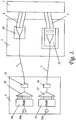
- an ATM switch core comprising an N x N passive optical cross-connect core 1 and a set of N port cards 2, of which only one is illustrated in Figure 1.
- Associated with the ATM switch core 1 is a set of up to N satellites 3, of which similarly only one is illustrated in Figure 1.
- the N port cards 2, and the up to N satellites 3 may be arranged in stacks in which each individual port card 2 and satellite 3 occupies a different layer in its stack. For convenience of description those individual port cards and satellites will be treated as arranged in layers irrespective of whether or not that is their actual physical arrangement.
- Each satellite has an input random access memory (RAM) 30 and one output RAM 31, and each satellite is connected with its associated port card, which is at the same level, by means of an optical fibre 4 for the transmission of ATM cells from the satellite to its associated port card, and by means of an optical fibre 5 for the transmission of cells in the opposite direction.
- RAM input random access memory
- Particular input and output ports 30a and 31a are connected respectively to the input and output RAMs 30 and 31 of the different satellite layers.
- routing information specifying the output port to which the interconnect is required to direct that cell.
- This output port may happen to be the output port 31a connected with the output RAM 31 on the same satellite as the input RAM 30 that initially received the cell, but in general it will be one that is connected with the output RAM 31 on one of the other satellites. If the routing involves moving the cell from one satellite to another, this is achieved via the passive optical cross-connect, of the switch core.
- the cross-connect 1 may similarly be involved when the routing does not involve moving from one satellite level to another.
- the ATM cells that are applied to each of these port cards by way of its associated optical fibre 4 are applied equally to each of the N optical fibres of an associated N-way optical fibre ribbon 6 by which that port card is connected with one end of the passive optical cross-connect core 1.
- Each port card is similarly connected by means of an N-way optical fibre ribbon 7 with the other end of the cross-connect core 1.
- the internal 'wiring' of this passive optical cross-connect core 1 is such that one fibre of each ribbon 7 is optically coupled with one of the fibres of each of the N different ribbons 6.
- each ribbon 7 supplies, to its associated port card 2, N different inputs, one corresponding to each one of the N different inputs applied to the N port cards 2 of the switch core by way of the N fibres 4.
- an optical selector 22 associated with that card selects which one of the N fibres of its associated fibre ribbon 7 should at any one time be optically coupled with fibre 5 in this way establishing an optical coupling between the fibre 5 of this level of port card and satellite and the fibre 4 of a selected (same or different) level of port card and satellite.
- the ATM switch core comprising the passive optical cross-connect core 1 and port cards 2 contains no buffering, and so the interconnect has to be operated so that the reading out of ATM cells from the RAMs 30, the switching of the space switches 22 and the writing of ATM cells into the RAMs 31 proceed with the appropriate synchronisation to achieve the desired cell routing.
- This is achieved by means of a logic unit (not shown) which is physically distributed between the different port cards 2, and which receives information from cell schedulers (not shown) which are located on the satellites 3, and which note the arrival of individual cells at the RAMs 20 and advise the logic unit of their respective destinations.
- Complete ATM cells read out from the RAMs 30, under the control of the logic unit are multiplexed in associated multiplexers 32 and fed to associated optical transmitters 33 whose optical outputs are optically coupled with the optical fibres 4.
- the multiplexed ATM cells impressed on the optical signals delivered to the individual satellites 3 by way of their associated fibres are fed to associated receivers 34 before being demultiplexed in associated demultiplexers 35 and written as complete individual ATM cells into their associated RAMs 31.
- the passive N-way splitter 20 may be constructed in optical fibre format, or it may be constructed in an integrated optics format, as depicted in Figure 2.
- a simple single mode optical waveguide 201 and a set of N single mode waveguides 202 are created in a substrate 200, the distal ends of these waveguides being respectively coupled with the single optical fibre 4 and the individual fibres of the optical fibre ribbon 6.
- a region 203 Between the proximal ends of the waveguides 201 and 202 is a region 203, where there is no lateral waveguiding structure, but in which waveguiding is retained only in the direction normal to the plane in which the waveguides 201 and 202 extend. In this region 203, light emerging from waveguide 201 spreads out laterally to cover the proximal ends of all N fibres 202.
- optical selector 22 has many features with their counterparts in the integrated optics splitter of Figure 2.
- the optical selector has waveguides 221 and 222 on a substrate 220, and a region 223 without a lateral waveguiding structure, having their counterparts respectively in waveguides 201 and 202 on substrate 200 with a region 203 having no lateral waveguiding structure.
- the principal difference is that each of the N waveguides 222 is provided with an associated amplifier 224. It is these amplifiers 224 which perform the switching function.
- the waveguide 221 may include an amplifier 225.
- the fibre of ribbons 6 and 7 in Figures 2 and 3 are shown in registry with, but spaced from, the waveguide 202 and 222 on the substrates 200 and 220.
- a preferred way of achieving the requisite optical coupling between the individual fibres of the ribbons and the waveguides formed in the substrates is to house the ends of the fibres in grooves (not shown) photo lithographically etched in the substrates.
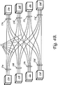
- the function of the passive optical cross-connect core 1 is to connect one fibre of each of the N ribbons 6 with one of the N fibres of each of the N ribbons 7.
- the individual fibres of the fibre ribbons 6 and 7 of the first port card 2 are labelled 6A01 to 6A16, and 7A01 to 7A16.
- those of second port card are labelled 6B01 to 6B16, and 7B01 to 7B16.
- the labelling continues in similar fashion to the sixteenth port card 2, the fibres of which are accordingly labelled 6P01 to 6P16, and 7P01 to 7P16.
- the preferred arrangement of interconnection provided by the core 1 is that in which the fibres of the ribbon 6 of the first port card 2 are connected according to the schedule:
- 6A01 is connected with 7A01, 6A02 with 7B01, 6A03 with 7C01, and so on till the connection of 6A16 with 7P01.
- the corresponding interconnections for the fibres of ribbon 6 of the second port card 2 are that 6B01 is connected with 7A02, 6B02 with 7B02, 6B03 with 7C02, and so on till the connection of 6B16 with 7P02.
- the interconnections for the succeeding port cards 2 proceeds in the same fashion so that in respect of the sixteenth port card 2, the interconnections are that 6H01 is connected with 7A16, 6H02 with 7B16, 6H03 with 7C16, and so on till the connection of 6H16 with 7H16.
- a particular feature to be noted in respect of this preferred arrangement is that the arrangement is separable into subunits. This can be seen by looking for instance at the interconnections of the first four fibres of each ribbon 6 of the first four port cards 2. These are: 6A01 ⁇ 7A01 6B01 ⁇ 7A02 6C01 ⁇ 7A03 6D01 ⁇ 7A04 6A02 ⁇ 7B01 6B02 ⁇ 7B02 6C02 ⁇ 7B03 6D02 ⁇ 7B04 6A03 ⁇ 7C01 6B03 ⁇ 7C02 6C03 ⁇ 7C03 6D03 ⁇ 7C04 6A04 ⁇ 7D01 6B04 ⁇ 7D02 6C04 ⁇ 7D04 ⁇ 7D04 ⁇ 7D04 ⁇ 7D04 ⁇ 7D04 ⁇ 7D04 ⁇ 7D04 ⁇ 7D04 ⁇ 7D04 ⁇ 7D04 ⁇ 7D04 ⁇ 7D04 ⁇ 7D04 ⁇ 7D04 ⁇ 7D04 ⁇ 7D04
- Such a subunit can readily be constructed from a stacked array of four fibre ribbons, each of four fibres.
- Such an array of four fibre ribbons is schematically depicted in Figure 4B, though for illustrative convenience these four ribbons, which are indicated generally at 10a, 10b, 10c, 10d, are shown spaced apart.
- the fibre ribbons terminate in individual fibre ribbon terminations 11a to 11d.
- the individual fibres 12 are separated out from their respective ribbons and then reassembled into four new ribbons indicated generally at 13a to 13d, each similarly of four fibres, these new ribbons terminating in individual fibre ribbon terminations 14a to 14d.
- each of the two sets of four ribbon terminations 11 and 14 is replaced by a single termination accommodating all four ribbons.
- the subunit has eight eight fibre ribbons instead of four four fibre ones.
- each of the 32 satellites 3 must be capable of sending and receiving traffic over its associated pair of optical fibres 4 and 5 at the rate of 40 Gbit/s.
- This traffic is wavelength multiplexed so that no individual channel of the wavelengths multiplexed signal is required to handle traffic at a rate in excess of 10 Gbit/s. It is clear that four-way wavelength multiplexing is sufficient to meet this target, but this would mean that the data on each of the four channels would be entirely independent of that on each of the other three channels.
- the power level in the multiplexed transmission path would be liable to fluctuate anywhere between that pertaining to the concurrence of four low-level bits and that pertaining to the concurrence of four high-level bits.
- power fluctuations are undesirable, particularly if the multiplexed signals are to be optically amplified in their multiplexed state.
- eight-way wavelength multiplexing is actually chosen so that this problem can be avoided by arranging the eight channels in four pairs, one member of each pair carrying the inverse of the data of the other member.
- the two channels of such a pair can be created by driving two lasers in push-pull or, in some circumstances more conveniently, by frequency shift keying a single laser.
- FIG. 5a and 5b Suitable alternative forms of combiner for the transmitter 37 of a satellite 3 are depicted in Figures 5a and 5b which employ eight and four lasers 330 respectively.
- These lasers 330 are provided with fibre pigtails 331 which are coupled with individual members of a set of integrated optics waveguides 332 created in a substrate 333.
- the set of waveguides 332 are optically coupled with a single integrated optics waveguide 334 via a region 335 in which there is no lateral waveguiding structure, but in which waveguiding is retained only in the direction normal to the plane in which waveguides 332 and 334 extend.
- This form of combiner is lossy, and so an optical amplifier 336 may be included in waveguide 334.
- the distal end of waveguide 334 is optically coupled with optical fibre 4.
- the incoming signal on fibre 5 has to be wavelength demultiplexed into eight physically separated channels and fed to eight physically separated channels for feeding to eight separate photodetectors 340 (Fig. 6) of the detector 34 ( Figure 1).
- These photodetectors 340 are preferably arranged in physically adjacent pairs, of which one member receives one of the 10 Gbit/s data streams, while the other member receives the inverse (complement) data stream. Under these circumstances the two outputs of each pair of photodetectors can conveniently be combined in push-pull configuration to give a single 10 Gbit/s output for onward feeding to the demultiplexer 35 (Fig. 1).
- Figure 6 schematically illustrates an integrated optics demultiplexer of a type that employs radiative star couplers interconnected by an array of M uncoupled integrated optics waveguides of different length.
- This type of demultiplexer may be thought of as a kind of generalisation of a 2x2 Mach Zehnder demultiplexer where the M waveguides act as a kind of diffraction grating.
- M waveguides act as a kind of diffraction grating.
- the demultiplexer of Figure 6 has a substrate 341 in which are created a set of eight optical waveguides 342 optically coupled by fibre pigtails 343 with the eight photodetectors 340, a set of M waveguides 344, and a single waveguide 345 optically coupled with the single optical fibre 5 associated with the satellite to which this demultiplexer belongs.
- the two ends of the set of M waveguides 344 are respectively optically coupled with the set of eight waveguides 342 and the single waveguide 345 by regions 346 and 347 in which there is no lateral waveguiding structure, but in which waveguiding is retained only in the direction normal to the plane in which the waveguides 342, 344 and 345 extend so that these regions function as radiative star couplers.
- the fibre pigtails that optically couple the eight waveguides 342 with the eight photodetectors 340 are dispensed with, and instead the photodetectors are mounted directly on, or are integrated with the substrate 341.
- the place of the interconnected radiative star couplers type demultiplexer may alternatively be taken by a diffraction grating type demultiplexer for instance of the type described in the specification of British Patent GB 2 222 891 B.
Landscapes
- Engineering & Computer Science (AREA)
- Computer Networks & Wireless Communication (AREA)
- Physics & Mathematics (AREA)
- Microelectronics & Electronic Packaging (AREA)
- General Physics & Mathematics (AREA)
- Optics & Photonics (AREA)
- Signal Processing (AREA)
- Optical Communication System (AREA)
- Data Exchanges In Wide-Area Networks (AREA)
- Use Of Switch Circuits For Exchanges And Methods Of Control Of Multiplex Exchanges (AREA)
Applications Claiming Priority (2)
| Application Number | Priority Date | Filing Date | Title |
|---|---|---|---|
| GB9410544 | 1994-05-26 | ||
| GB9410544A GB9410544D0 (en) | 1994-05-26 | 1994-05-26 | Switched optical interconnect |
Publications (2)
| Publication Number | Publication Date |
|---|---|
| EP0684747A2 true EP0684747A2 (fr) | 1995-11-29 |
| EP0684747A3 EP0684747A3 (fr) | 1999-11-24 |
Family
ID=10755743
Family Applications (1)
| Application Number | Title | Priority Date | Filing Date |
|---|---|---|---|
| EP95303098A Withdrawn EP0684747A3 (fr) | 1994-05-26 | 1995-05-05 | Interconnexion optique commutée |
Country Status (4)
| Country | Link |
|---|---|
| US (1) | US5633961A (fr) |
| EP (1) | EP0684747A3 (fr) |
| JP (1) | JPH08211428A (fr) |
| GB (2) | GB9410544D0 (fr) |
Families Citing this family (14)
| Publication number | Priority date | Publication date | Assignee | Title |
|---|---|---|---|---|
| GB2300086B (en) * | 1995-04-18 | 1999-08-04 | Northern Telecom Ltd | Switching arrangement |
| GB2311180B (en) * | 1996-03-13 | 2000-03-22 | Northern Telecom Ltd | Switch architecture |
| US5889610A (en) * | 1996-12-31 | 1999-03-30 | Lucent Technologies Inc. | Optical protection switching system |
| US5815613A (en) * | 1996-12-31 | 1998-09-29 | Lucent Technologies Inc. | Optical switched distributor |
| US5930013A (en) * | 1996-12-31 | 1999-07-27 | Lucent Technologies Inc. | Optical switched selector |
| US6449073B1 (en) | 1998-07-21 | 2002-09-10 | Corvis Corporation | Optical communication system |
| US7130540B2 (en) * | 1998-07-21 | 2006-10-31 | Corvis Corporation | Optical transmission systems, devices, and methods |
| CN1350653A (zh) * | 1998-09-16 | 2002-05-22 | 约尔特有限公司 | 无电子线路的无线光纤通信 |
| US6771905B1 (en) | 1999-06-07 | 2004-08-03 | Corvis Corporation | Optical transmission systems including optical switching devices, control apparatuses, and methods |
| WO2002067481A1 (fr) * | 2001-02-20 | 2002-08-29 | University Of Maryland, Baltimore County | Systeme optique integre largement accordable et procede associe |
| US6922529B2 (en) * | 2002-08-09 | 2005-07-26 | Corvis Corporation | Optical communications systems, devices, and methods |
| JP4757244B2 (ja) | 2006-08-23 | 2011-08-24 | 富士通株式会社 | 光ゲートアレイ装置及び光ゲートアレイモジュール |
| EP2923455A4 (fr) * | 2012-11-26 | 2016-08-31 | Viscore Technologies Inc | Procédés et systèmes de commutation optique passive |
| US20140270634A1 (en) * | 2013-03-13 | 2014-09-18 | Gary Evan Miller | Multi- purpose apparatus for switching, amplifying, replicating, and monitoring optical signals on a multiplicity of optical fibers |
Family Cites Families (4)
| Publication number | Priority date | Publication date | Assignee | Title |
|---|---|---|---|---|
| GB8727260D0 (en) * | 1987-11-20 | 1987-12-23 | British Telecomm | Switched optical network |
| JPH0834611B2 (ja) * | 1989-01-27 | 1996-03-29 | 日本電気株式会社 | 波長分割光交換方式 |
| DE4209790A1 (de) * | 1992-03-26 | 1993-09-30 | Sel Alcatel Ag | Mehrstufige Vermittlungseinrichtung für optische Signale |
| JP3158706B2 (ja) * | 1992-09-09 | 2001-04-23 | 株式会社日立製作所 | 光分配装置 |
-
1994
- 1994-05-26 GB GB9410544A patent/GB9410544D0/en active Pending
-
1995
- 1995-05-05 EP EP95303098A patent/EP0684747A3/fr not_active Withdrawn
- 1995-05-10 GB GB9509504A patent/GB2289813B/en not_active Expired - Fee Related
- 1995-05-24 JP JP7149480A patent/JPH08211428A/ja active Pending
- 1995-05-26 US US08/451,135 patent/US5633961A/en not_active Expired - Fee Related
Non-Patent Citations (3)
| Title |
|---|
| AKIRA M ET AL: "SIGNAL SELF-THRESHOLDING USING WAVELENGTH-DIVISION MULTIPLEXED DIFFERENTIAL TRANSMISSION FOR PHOTONIC ATM SWITCHES" ELECTRONICS LETTERS, vol. 29, no. 15, 22 July 1993 (1993-07-22), pages 1337-1338, XP000385662 ISSN: 0013-5194 * |
| CHAWKI M J ET AL: "DEMONSTRATION OF A HIGH SPEED OPTICAL DROP FUNCTION USING A TUNABLE DFB LASER" ELECTRONICS LETTERS, vol. 29, no. 2, 21 January 1993 (1993-01-21), pages 193-195, XP000350770 ISSN: 0013-5194 * |
| YUTAKA KATSUYAMA ET AL: "PROPOSAL ON ADOPTION OF POLARIZATION-CONTROLLED SWITCH FOR SURVIVABLE FIBER NETWORKS AND DEMONSTRATION OF SIMULTANEOUS FDM/WDM SIGNAL SWITCHING" JOURNAL OF LIGHTWAVE TECHNOLOGY, vol. 10, no. 10, 1 October 1992 (1992-10-01), pages 1507-1512, XP000320339 ISSN: 0733-8724 * |
Also Published As
| Publication number | Publication date |
|---|---|
| GB2289813A (en) | 1995-11-29 |
| EP0684747A3 (fr) | 1999-11-24 |
| GB2289813B (en) | 1998-05-13 |
| JPH08211428A (ja) | 1996-08-20 |
| GB9509504D0 (en) | 1995-07-05 |
| US5633961A (en) | 1997-05-27 |
| GB9410544D0 (en) | 1994-07-13 |
Similar Documents
| Publication | Publication Date | Title |
|---|---|---|
| US6335992B1 (en) | Scalable optical cross-connect system and method transmitter/receiver protection | |
| US5548431A (en) | Bidirectional multi-channel optical ring network using WDM techniques | |
| US6069719A (en) | Dynamically reconfigurable optical add-drop multiplexers for WDM optical communication systems | |
| US5633961A (en) | Switched optical interconnect | |
| CA2285128C (fr) | Commutateur pour signaux optiques | |
| US6333799B1 (en) | Hybrid wavelength-interchanging cross-connect | |
| EP1162860A2 (fr) | Architecture à échelle variable, d' un routeur IP optique WDM | |
| JP3139540B2 (ja) | 光スイッチ網 | |
| US6535312B2 (en) | Versatile optical switching for wavelength-division multiplexed system | |
| JP3977430B2 (ja) | 色分散補償用ノード | |
| US6411412B1 (en) | WDM optical communication network with data bridging plural optical channels between optical waveguides | |
| US6348985B1 (en) | Bidirectional WDM optical communication network with data bridging plural optical channels between bidirectional optical waveguides | |
| CA2372536C (fr) | De blocage planaires de longueur d'onde lumineuse faisant appel a des micromachines | |
| US20020131678A1 (en) | Wavelength-modular optical cross-connect switch | |
| US9025915B2 (en) | Method and module for switching optical signals having different modes of propagation | |
| Eldada | Advances in ROADM technologies and subsystems | |
| EP0946077A2 (fr) | Appareil de commutation optique utilisant la technologie de multiplexage en longueur d'onde | |
| US6643463B1 (en) | Optical wavelength division multiplexing transmission network system using transmitting/receiving apparatuses having 2-input and 2-output optical path switching elements | |
| US20040258411A1 (en) | Node for an optical network | |
| US7058302B2 (en) | Frequency extractor | |
| KR20210122400A (ko) | 데이터 센터 내부 네트워크용 InP 기반의 광집적 스위치 모듈 | |
| US20020159678A1 (en) | Optical switch for routing signals and a network incorporating same | |
| US7072538B1 (en) | Planar reconfigurable optical add/drop module | |
| US7020356B2 (en) | Selection module for an optical signal switch and an optical signal switch | |
| US20020109880A1 (en) | Method and apparatus for switching wavelength-division-multiplexed optical signals |
Legal Events
| Date | Code | Title | Description |
|---|---|---|---|
| PUAI | Public reference made under article 153(3) epc to a published international application that has entered the european phase |
Free format text: ORIGINAL CODE: 0009012 |
|
| AK | Designated contracting states |
Kind code of ref document: A2 Designated state(s): DE FR SE |
|
| RAP3 | Party data changed (applicant data changed or rights of an application transferred) |
Owner name: NORTEL NETWORKS CORPORATION |
|
| PUAL | Search report despatched |
Free format text: ORIGINAL CODE: 0009013 |
|
| AK | Designated contracting states |
Kind code of ref document: A3 Designated state(s): DE FR SE |
|
| RIC1 | Information provided on ipc code assigned before grant |
Free format text: 6H 04Q 11/00 A, 6H 04Q 11/04 B, 6H 04L 12/56 B |
|
| RAP1 | Party data changed (applicant data changed or rights of an application transferred) |
Owner name: NORTEL NETWORKS LIMITED |
|
| STAA | Information on the status of an ep patent application or granted ep patent |
Free format text: STATUS: THE APPLICATION IS DEEMED TO BE WITHDRAWN |
|
| 18D | Application deemed to be withdrawn |
Effective date: 20000525 |