EP0685217A1 - Lit pour malades - Google Patents
Lit pour malades Download PDFInfo
- Publication number
- EP0685217A1 EP0685217A1 EP95107173A EP95107173A EP0685217A1 EP 0685217 A1 EP0685217 A1 EP 0685217A1 EP 95107173 A EP95107173 A EP 95107173A EP 95107173 A EP95107173 A EP 95107173A EP 0685217 A1 EP0685217 A1 EP 0685217A1
- Authority
- EP
- European Patent Office
- Prior art keywords
- bed
- attachment
- bed according
- display element
- control device
- Prior art date
- Legal status (The legal status is an assumption and is not a legal conclusion. Google has not performed a legal analysis and makes no representation as to the accuracy of the status listed.)
- Withdrawn
Links
- 238000001514 detection method Methods 0.000 claims abstract description 10
- 230000007246 mechanism Effects 0.000 claims description 3
- 230000004913 activation Effects 0.000 claims 1
- 230000004888 barrier function Effects 0.000 description 20
- 238000011161 development Methods 0.000 description 6
- 230000018109 developmental process Effects 0.000 description 6
- 230000005540 biological transmission Effects 0.000 description 4
- 238000005253 cladding Methods 0.000 description 4
- 238000010276 construction Methods 0.000 description 4
- 230000008901 benefit Effects 0.000 description 3
- 230000008859 change Effects 0.000 description 2
- 238000010586 diagram Methods 0.000 description 2
- 230000009471 action Effects 0.000 description 1
- 239000011248 coating agent Substances 0.000 description 1
- 238000000576 coating method Methods 0.000 description 1
- 230000000694 effects Effects 0.000 description 1
- 230000005672 electromagnetic field Effects 0.000 description 1
- 230000007613 environmental effect Effects 0.000 description 1
- 238000010438 heat treatment Methods 0.000 description 1
- 239000000463 material Substances 0.000 description 1
- 238000000034 method Methods 0.000 description 1
- 230000008569 process Effects 0.000 description 1
- 230000005855 radiation Effects 0.000 description 1
- XLYOFNOQVPJJNP-UHFFFAOYSA-N water Substances O XLYOFNOQVPJJNP-UHFFFAOYSA-N 0.000 description 1
Images


Classifications
-
- A—HUMAN NECESSITIES
- A47—FURNITURE; DOMESTIC ARTICLES OR APPLIANCES; COFFEE MILLS; SPICE MILLS; SUCTION CLEANERS IN GENERAL
- A47C—CHAIRS; SOFAS; BEDS
- A47C19/00—Bedsteads
- A47C19/04—Extensible bedsteads, e.g. with adjustment of length, width, height
- A47C19/045—Extensible bedsteads, e.g. with adjustment of length, width, height with entire frame height or inclination adjustments
-
- A—HUMAN NECESSITIES
- A61—MEDICAL OR VETERINARY SCIENCE; HYGIENE
- A61G—TRANSPORT, PERSONAL CONVEYANCES, OR ACCOMMODATION SPECIALLY ADAPTED FOR PATIENTS OR DISABLED PERSONS; OPERATING TABLES OR CHAIRS; CHAIRS FOR DENTISTRY; FUNERAL DEVICES
- A61G7/00—Beds specially adapted for nursing; Devices for lifting patients or disabled persons
- A61G7/002—Beds specially adapted for nursing; Devices for lifting patients or disabled persons having adjustable mattress frame
- A61G7/012—Beds specially adapted for nursing; Devices for lifting patients or disabled persons having adjustable mattress frame raising or lowering of the whole mattress frame
-
- A—HUMAN NECESSITIES
- A61—MEDICAL OR VETERINARY SCIENCE; HYGIENE
- A61G—TRANSPORT, PERSONAL CONVEYANCES, OR ACCOMMODATION SPECIALLY ADAPTED FOR PATIENTS OR DISABLED PERSONS; OPERATING TABLES OR CHAIRS; CHAIRS FOR DENTISTRY; FUNERAL DEVICES
- A61G7/00—Beds specially adapted for nursing; Devices for lifting patients or disabled persons
- A61G7/002—Beds specially adapted for nursing; Devices for lifting patients or disabled persons having adjustable mattress frame
- A61G7/015—Beds specially adapted for nursing; Devices for lifting patients or disabled persons having adjustable mattress frame divided into different adjustable sections, e.g. for Gatch position
-
- A—HUMAN NECESSITIES
- A61—MEDICAL OR VETERINARY SCIENCE; HYGIENE
- A61G—TRANSPORT, PERSONAL CONVEYANCES, OR ACCOMMODATION SPECIALLY ADAPTED FOR PATIENTS OR DISABLED PERSONS; OPERATING TABLES OR CHAIRS; CHAIRS FOR DENTISTRY; FUNERAL DEVICES
- A61G7/00—Beds specially adapted for nursing; Devices for lifting patients or disabled persons
- A61G7/002—Beds specially adapted for nursing; Devices for lifting patients or disabled persons having adjustable mattress frame
- A61G7/018—Control or drive mechanisms
-
- A—HUMAN NECESSITIES
- A61—MEDICAL OR VETERINARY SCIENCE; HYGIENE
- A61G—TRANSPORT, PERSONAL CONVEYANCES, OR ACCOMMODATION SPECIALLY ADAPTED FOR PATIENTS OR DISABLED PERSONS; OPERATING TABLES OR CHAIRS; CHAIRS FOR DENTISTRY; FUNERAL DEVICES
- A61G7/00—Beds specially adapted for nursing; Devices for lifting patients or disabled persons
- A61G7/05—Parts, details or accessories of beds
- A61G7/0528—Steering or braking devices for castor wheels
-
- A—HUMAN NECESSITIES
- A61—MEDICAL OR VETERINARY SCIENCE; HYGIENE
- A61G—TRANSPORT, PERSONAL CONVEYANCES, OR ACCOMMODATION SPECIALLY ADAPTED FOR PATIENTS OR DISABLED PERSONS; OPERATING TABLES OR CHAIRS; CHAIRS FOR DENTISTRY; FUNERAL DEVICES
- A61G7/00—Beds specially adapted for nursing; Devices for lifting patients or disabled persons
- A61G7/002—Beds specially adapted for nursing; Devices for lifting patients or disabled persons having adjustable mattress frame
- A61G7/005—Beds specially adapted for nursing; Devices for lifting patients or disabled persons having adjustable mattress frame tiltable around transverse horizontal axis, e.g. for Trendelenburg position
Definitions
- the invention relates to a bed, in particular a hospital bed, consisting of a bed frame and a bed attachment with a bed frame that is guided in a height-adjustable manner in the bed frame, the bed attachment being height-adjustable by means of two independently actuable drive motors.
- the drive motors are preferably electric motors. They are used to adjust the height of the bed attachment.
- the bed attachment usually consists of a head part, a foot part and bed sides.
- the bed frame includes a bed surface. Safety side panels may be present over the bed sides.
- a hospital bed according to the preamble of claim 1 is known from DE-GM 92 07 352. Characterized in that the motors for the head part and the foot part of the bed attachment can be operated separately and independently of one another in the known bed, the bed attachment can run both horizontally and inclined (in the so-called Trendelenburg position).
- a hospital bed is known in which the bed attachment is connected to four vertical telescopic tubes which are essentially square in cross section, in each of which a telescopic rod is guided so as to be longitudinally displaceable.
- Each telescopic rod is provided with a roller at its lower end. All telescopic rods can be extended simultaneously by a motor. However, the movement of all four telescopic rods is coupled to one another, so that an inclination of the bed attachment is not possible.
- a sick bed which has a bed frame with an adjustable lying surface. Either the head part of the bed surface as well as the foot part of the bed surface are adjustable, each by a separate motor. The motors are connected to the bed frame.
- the US-PS 28 19 474 discloses a similar hospital bed, in which the bed frame is also provided with an adjustable lying surface, both the head part of the lying surface and the foot part of the lying surface can be adjusted by a separate motor.
- a bed, in particular a hospital bed, of the type mentioned at the outset should be able to maintain the horizontal position of the bed attachment when the height is adjusted. Since there is a separate motor for the head part and for the foot part, and since the forces acting on the head part and the foot part can be of different magnitudes, the motors generally do not run synchronously. In the normal case, the lifting speeds for the head part and the foot part are of different sizes, so that the bed attachment gradually reaches an inclined position.
- the object of the invention is to propose a bed, in particular a hospital bed, of the type specified at the outset, which maintains a certain position of the bed attachment, in particular a horizontal position of the bed attachment, when the height of the bed attachment is adjusted.
- the bed has a horizontal control device for the bed attachment with an inclination detection device for detecting the inclination of the bed attachment relative to the bed frame and with a control device for controlling the drive motors.
- the drive motors are controlled so that the bed attachment opposite the bed frame has the desired inclination.
- the drive motors can be controlled in such a way that the bed attachment assumes and maintains a horizontal position with respect to the bed frame.
- control device slows down or stops the drive motor that drives the part of the bed attachment that is leading in the respective direction of movement.
- the bed therefore has a control device for slowing down or stopping that drive motor which drives the part (head part or foot part) of the bed attachment which is leading in the respective direction of movement.
- the inclination detection device is suitable for determining the horizontal position of the bed and for determining deviations from the horizontal position, preferably in both directions. Depending on the inclination of the bed attachment, which has been determined by the inclination detection device, the drive motor that drives the preceding part is slowed down or stopped.
- the drive motor which moves the head part is stopped when the bed attachment moves upwards.
- the other drive motor is stopped during the downward movement, i.e. the drive motor that moves the foot section, since in this case the foot section is the part of the bed attachment that runs in the direction of movement (downward).
- a further advantageous development is characterized in that the control device accelerates the drive motor which drives the part of the bed attachment which is trailing in the respective direction of movement.
- the horizontal control device is deactivated when the motors for the head part and the foot part of the bed attachment are activated individually.
- the horizontal control device can therefore be deactivated in order to move the head part or the foot part upwards or downwards, as a result of which the bed attachment is inclined. Accordingly, the horizontal control device only comes into action when the motors for the head part and the foot part are actuated together.
- the arrangement can be such that various switches or buttons are present in an actuating device for the upward movement of the head part, for the downward movement of the head part, for the upward movement of the foot part and for the downward movement of the foot part as well as for the upward movement of the head and foot part and for the downward movement of the head and foot section (a total of six switches or buttons).
- the horizontal control device is activated when the buttons for simultaneous upward or downward movement of the head and foot sections are pressed.
- the horizontal control device is deactivated when a button for a separate upward or downward movement of the head part or the foot part is actuated.
- the horizontal control device preferably has an element which interacts with at least one stop element.
- the element is preferably designed to be resilient, for example as a spring bar or resilient bar or as a blocked spring, but also in another suitable manner.
- the stop element or elements can be provided on the bed attachment, for example on a side surface of the bed attachment.
- the element is connected to a component that can be moved in height with the bed attachment, but cannot be inclined. The element moves up and down with the bed attachment. However, any inclinations of the bed attachment are not carried out by the element.
- the kinematically reversed arrangement can also be selected, in which the stop element or elements are connected to a component which is vertically movable but not inclinable with the bed attachment, and in which the element is provided on the bed attachment.
- Switches are preferably provided which can be actuated by the element.
- the switch or switches can be connected to the element and / or the housing for the element. By actuating the switches, the control device is informed whether and, if appropriate, in which direction and, if appropriate, to what extent the bed attachment is inclined.
- a further advantageous development is characterized in that the head part and the foot part of the bed attachment are provided with at least one, preferably each with two downward-pointing telescopic rods which are guided in associated telescopic guides of the bed frame.
- the arrangement can also be reversed: then the head part and the foot part of the bed attachment are provided with at least one or two downward-pointing telescopic guides, in which associated telescopic rods of the bed frame are guided.
- the telescopic rods of the head part and / or of the foot part are each connected to one another by a cross member.
- the traverse preferably runs essentially horizontally.
- the bed attachment is connected to the traverse. The stability is increased by the traverse.
- the telescopic rods are each provided with a spindle drive, which can be driven by a common toothed belt.
- the telescopic guides can each be provided with a spindle drive by way of kinematic reversal.
- another flexible force transmission element which also ensures the synchronization of the spindle drives, can be used, for example a chain.
- the use of such a force transmission element has the advantage that the drive option for the vertical movement of the bed cap can be reliably implemented in a simple manner even when the bed cap is inclined, since angular compensation can be reliably achieved in a simple manner.
- the inclination detection device has a movable display element.
- the display element can be scanned by one or more sensors. These can be light barriers, for example, light-sensitive sensors. However, other sensors such as proximity switches or the like are also possible.
- the display element is preferably rotatable. However, it is also possible to use a longitudinally movable display element.
- the display element is preferably designed as an aperture. It is also preferably designed as an arc segment. This is particularly advantageous when the display element is rotatable.
- a cutout is preferably provided in the circular arc segment. This makes it possible to recognize not only a preferred inclination, such as the horizontal position, but also other inclinations.
- the transmission preferably has a swivel lever connected to the display element.
- a lever mechanism can be implemented in a particularly simple and cost-saving manner. It is particularly advantageous if a connecting rod is connected to the swivel lever.
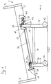
- the bed shown in FIG. 1 consists of a bed frame 1 and a height-adjustable bed attachment 2 with a bed frame, not shown in FIG. 1, which has a lying surface.
- the bed frame 2 has side parts 3 (bed sides) and corner pillars 4.
- the bed frame 1 consists of a cover 9 on the head side and a cover 10 on the foot side, which are connected to one another by frame parts 11. At the outer lower ends of the panels 9, 10 rollers 12 are provided.
- the cladding 10 is partially shown in section in FIG. 2. It has two parallel, spaced, vertical telescopic guides 13, 14, in each of which a vertical telescopic rod 15, 16 is guided so as to be longitudinally displaceable.
- the telescopic rods 15, 16 are connected to one another at their upper ends by a horizontal crossmember 17 on which the bed attachment 2 rests (not shown in FIG. 2).
- the telescopic rod 15 (and also the other telescopic rods) has at its lower end a slide ring 18 made of a friction-reducing coating, the outer surface of which rests on the inner surface of the telescopic guide 13.
- a further slide ring 19 is provided, which is also made of a friction-reducing material and which rests with its inner surface on the outer surface of the telescopic rod 15.
- a spindle 20 is rotatable, but not axially displaceable.
- the spindle 20 passes through a spindle nut 21 which is connected to the bottom 23 of the casing 10 via a vertical sleeve 22. Accordingly, the spindle and with it the telescopic rod 15 can be moved up or down by rotating the spindle 20 relative to the spindle nut 21 and thus to the casing 10.
- an electric motor 24 is attached to the cross member 17, which drives a belt wheel 25, around which a toothed belt 26 is wound.
- the toothed belt is deflected around deflection rollers 27 on its non-toothed rear side in a direction parallel to the cross member 17.
- the gear wheels 28, 29 are rotatable relative to the associated telescopic rods 15, 16, but are axially fixed.
- the gear 28 (and correspondingly also the gear 29) is connected to the associated spindle 20, so that the rotation of the gear 28 is transmitted to the spindle 20.
- a further motor M1 is fastened to the crossmember 17, which connects the two parallel ones via the connecting shaft 30 and the belt wheel 31 as well as the toothed belt 32 and the toothed wheel 33 and a further toothed wheel located behind it in FIG. 1 , vertical, spaced telescopic poles moved up or down.
- the cladding 9 is constructed in exactly the same way as the cladding 10. The same applies to the associated telescopic rods, of which only the front telescopic rod 34 can be seen in FIG. 1.
- the motors M1 and M2 are housed or encapsulated in a closed, watertight housing 35. This allows the bed to be cleaned quickly and easily.
- the housing 35 is splash-proof. Depending on requirements, it can also be protected more effectively against water and / or other environmental influences.
- the housing 35 in which the motors M1 and M2 are encapsulated, is located at the foot part of the bed or the bed attachment. There it is the least disturbing when operating the bed. Furthermore, this has the further advantage that the electromagnetic fields of the electric motors arise at a location which is not very harmful to the patient. Characterized in that the electric motors M1 and M2 are encapsulated in a housing 35, there is the further advantage that the wiring effort for the electric motors M1, M2 is low.
- the housing 35 is connected to the crossbar 17 connecting the telescopic rods 15, 16. As a result, the housing is moved up and down together with this cross member 17 and thus also together with the associated foot part of the bed attachment 2.
- the lying surface 36 which consists of four parts which are connected to one another in an articulated manner, namely the head part 37, the central part 38 and the foot part which in turn consists of two parts 39, 40.
- the lying surface 36 can be designed, for example, as a slatted frame, but also as a grid surface or in some other way.
- An electric motor 41 is arranged in the housing 35 and can rotate a threaded spindle 42 which passes through a threaded nut 43.
- the threaded nut 43 is connected to a tube 44 which is guided in a longitudinally displaceable manner in a bore 45 of the guide tube 46.
- the spindle nut 43 is connected to the guide tube 46 in a longitudinally displaceable and rotationally fixed manner.
- one arm 47 of a two-armed lever is rotatably mounted, the other arm of which is supported with its outer end 49 on the underside of the head part 37.
- the two-armed lever 47, 48 is rotatably mounted about an axis 51 at the outer end of a connecting rod 50.
- the other end of the connecting rod 50 is connected to the electric motor 41 or its housing.
- the possibility of movement for the foot part 39, 40 of the lying surface 36 is constructed in an analogous manner.
- the motor 53 which is also arranged in the housing 35, rotates a spindle which passes through a spindle nut which is connected to a tube 54.
- a lever arm 55 of a two-armed lever is attached, the other lever arm 56 of which rests with its end 57 on the underside of the part 39 of this lying surface 36 facing the central part 38 of the lying surface 36.
- the two-armed lever 55, 56 is rotatably mounted about an axis 58.
- the connecting rod 59 is connected on the one hand to the axis of rotation 58 and on the other hand to the electric motor 53.
- the distance between the rollers 12 is greater than the distance between the telescopic guides 13, 14 and the distance between the telescopic rods 15, 16.
- the telescopic guides 13, 14 are accordingly in the casing 10 within the rollers 12 and recesses 60 provided for this purpose. This makes it possible to save overall height for the cladding 10.
- the telescopic guides 13, 14 can thus very far down and almost to the bottom 61 on which the rollers 12th lie on, reach.
- All electric motors M1, M2, 41 and 53 can be operated independently of one another. Since the electric motors M1 and M2 can be actuated independently of one another, the bed attachment 2 can be inclined in the manner shown in FIG. 1.
- the bed attachment 2 is rotatably mounted about the axis 62 at the foot end of the bed.
- the axis 62 is connected to the crossmember 17. It can be formed by horizontal extensions which are provided at the lower ends of side parts 63 connected to the crossmember 17 (see also FIG. 2).
- the bed attachment 2 is similarly rotatably mounted about an axis 64 provided on the traverse there.
- an upward-pointing pivot lever 65 is rotatably mounted on the axis of rotation 64, the upper end of which is rotatably supported on the side part 3 of the bed attachment construction 2 about an axis 66.
- the height adjustment of the head end of the bed attachment 2 is also reliably ensured in the case of the inclination shown in FIG. 1, since the toothed belt 32 transmits the force from the belt wheel 31 to the toothed wheels 33 even at an inclination.
- the shaft outputs of the motors M1, M2 are sealed off from the housing 35, which can be a plastic housing, with shaft seals. All drive motors are driven by a battery or a rechargeable battery, which is also arranged in the housing 35. A built-in transformer is not required, so that the associated disadvantages (heating, radiation, disconnection from the mains, etc.) do not occur.
- the hospital bed is completely free of mains voltage. If a battery is used, it can be charged by a charger that is located outside the bed and is not connected to the bed, for example a plug-in charger with a power of, for example, 15 VA, which can be connected to the hospital bed with a low-voltage line for occasional charging.
- All of the wheels 12 can be locked or locked, specifically by means of a single locking device which can be actuated from both sides of the bed by foot levers 67 shown in FIG. 3.
- the foot levers 67 are connected to a first brake rotary shaft 68, through which the rollers 12 can be locked at the foot end of the bed.
- Power is transmitted to the head end by a brake pressure rod 69, which is accommodated in a frame connection 11.
- the brake push rod 69 is connected to the brake rotary shaft 70 in the cover 9 at the head end of the bed.
- a control unit 71 is connected to the telescopic tube 15 or 16 or the traverse 17.
- the control unit 71 is located at a distance a from the telescopic tubes 15, 16 or their longitudinal axes.
- Two stop elements 72a, 72b are arranged on the bed attachment 2 or one of its side parts 3, specifically at a distance b from the telescopic tubes 15, 16 or their longitudinal axes.
- the stop elements 72a, 72b are arranged one above the other. They have a vertical distance c from each other.
- the housing of the control unit 71 is fastened to a connecting rod 73 which extends from the crossmember 17 to the outer foot end of the Bed protrudes. From the housing of the control unit 71, a resilient display element 74 points towards the center of the bed. When the bed cap 2 is in a horizontal position (FIGS. 5 and 6), the inner end of the resilient display element 74 lies exactly in the middle between the two stop elements 72a and 72b.
- the position of the display device 71 does not change. Accordingly, the position of the resilient display element 74 initially remains unchanged. However, the bed attachment 2 is inclined relative to the connecting rod 73, the control unit 71 and the resilient display element 74. As a result, depending on the direction of inclination, either the lower stop element 72a or the upper stop element 72b strikes the inner end of the resilient display element 74. If the bed attachment 2 is further inclined, the resilient display element is moved up or down accordingly. As a result, one of the two switches 75a or 75b provided in the control unit 71 is actuated. The switch 75a is located below the resilient display element 74, the switch 75b is located above this resilient display element 74.
- An actuating part 76 is connected to the resilient display element 74, which projects above the resilient display element 74 on both sides in the vertical direction. The ends of the actuating part 76 rest on switching elements 77a, 77b, which are thereby changed depending on the direction of movement of the resilient display element 74.
- the control unit causes the drive motor that drives the part of the bed attachment 2 that is leading in the respective direction of movement to be stopped. If, for example, the bed attachment 2 is inclined in the manner shown in FIG. 1 and the bed frame is to be moved upwards, the control causes only the motor M1 to run and the motor M2 to be stopped. Accordingly, only that in FIG. 1 head part of the bed shown on the left moved up. This continues until the bed attachment 2 lies horizontally. From then on, both motors are actuated so that the bed attachment 2 is moved upwards in the horizontal position.
- the control unit 71 causes the electric motor M1 to be stopped so that the height position at the head end of the bed is not changed. Furthermore, the control unit 71 causes the motor M2 to be actuated in the sense of a downward movement, so that the foot end of the bed attachment 2 is moved downward. This control is maintained until the bed attachment 2 is in a horizontal position. From then on, both motors are operated in the sense of a downward movement of the bed attachment.
- FIG. 7 A circuit diagram for such a control device is shown in FIG. 7.
- the motors M1 and M2 are for counterclockwise rotation and Suitable for clockwise rotation and switchable. Both motors can be operated individually upwards or downwards. They can also be operated upwards or downwards together. If the motor M1 is to be moved up, the button M1 ⁇ is actuated. If the motor M1 is to be moved down, the button M1 ⁇ is pressed. The motor M2 can be moved up or down in an analogous manner by pressing the M2 ⁇ or M2 ⁇ button.
- buttons are connected on one side to the positive pole of a voltage source.
- the other side of the buttons is connected to one or more of the relays RL1 to RL4 in the manner shown in FIG. 7 - partly via one or more diodes D7 to D10.
- the buttons for the common movement of motors M1 and M2 are connected via diodes D5 and D6 to a further relay RL5, which opens switches C1 and C2 when actuated.
- the double switches N.O. ("up") and N.U. 7 corresponds to the switches 77b and 77a in FIG. 6.
- the circuit part with the double switches N.O. and now. and the diodes D1 to D4 ensure that the one of the drive motors M1 and M2 is stopped which drives the part of the bed attachment which is leading in the respective direction of movement.
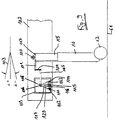
- FIG. 8 A modified embodiment is shown in FIG. 8, in which the inclination detection device has a movable display element 107.
- the display element 107 is on the with axis 106 connected to bed attachment 103 is rotatably supported. It is also designed as an aperture in the form of an arc segment.
- the display element 107 can be scanned by two sensors, namely by the two light barriers 112 and 114. The angular spacing of these sensors from one another is the same as the angle of the circular arc segment.
- the display element 107 is movable by a gear. This transmission is formed by the lever 101, the connecting rod 104 and the pivot lever 105.
- the cross member 117 connects the telescopic rods 15, 16 to one another in the manner described above.
- the lever 101 is firmly connected to the cross member 117. It is coupled to the pivot lever 105 via a connecting rod 104 such that small relative movements between the lever 101 and the pivot lever 105 are compensated for.
- the end of the lever 105 facing away from the connecting rod 104 is rotatable about the axis 106. Furthermore, the lever 105 is fixedly connected to the display element 107.
- the controller housing 109 is firmly seated on the bed structure 103 and is therefore connected to the bed structure 103.
- the bed structure 103 is rotatably mounted in the pivot point 110 located above the cross member 117.
- the pivot lever 105 and with it the display element 107 are also rotated.
- the vertical distance between the bed structure pivot point 110 and the axis of rotation 106 changes.
- the distance between the bed structure pivot point 110 and the axis of rotation 106 changes.
- the lever 105 sits on the axis 106 and can thereby move the display element 107 in the bearing 108 of the controller housing 109 by a positive angle ⁇ + or by a negative angle ⁇ .
- the ends of the circular arc segment of the diaphragm 107 cover the light barrier lenses 111 and 113 of the light barriers 112 and 114.
- Each light barrier consists of a light source and a light sensor and of light barrier lenses 111 and 113, the lie in the area of the light barriers 112 and 114.
- the swivel lever 105 moves the diaphragm 107 on the axis 106.
- a light barrier lens is "free".
- the control system recognizes this uncovered light barrier condition. It gives a signal to the corresponding drive motor so that its movement is slowed down or stopped for a short time. If necessary, this control process is then repeated. This restores the "horizontal" state.
- the control system works in such a way that the drive motor leading in the direction of movement is slowed down or stopped.
- Fig. 8 With the embodiment shown in Fig. 8 is still another Operating mode possible, namely the "Trendelenburg limitation”.
- the bed structure 103 is brought into the Trendelenburg position.
- a predetermined angle of, for example, 12 ° is reached.
- the "horizontal regulation” described above is not active for the Trendelenburg adjustment.
- One of the two drive motors is moved faster than the other drive motor. It is also possible not to move the other drive motor at all.
- both light barriers 112 and 114 are released.
- the control control uses this state, in that the aperture 107 releases both light barriers 112 and 114, as state detection, namely as the detection of the state "Trendelenburg position of the predetermined angle of, for example, 12 ° reached". In this state, the height drive motors are then stopped. It is understood that the circular arc distance of the light barriers 112 and 114, the circular arc length of the diaphragm 107 and the lever ratio of the gear consisting of the lever 101, the connecting rod 104 and the pivot lever 105 are dimensionally matched to the predetermined angle of the Trendelenburg adjustment.
- FIG. 9 shows a variant of the embodiment according to FIG. 8.
- the aperture 107 has a cutout 120.
- One leg of the diaphragm 107 is located on each side of the cutout 120.
- a further light barrier 115 with an associated lens 116 is provided between the two outer light barriers 112 and 114.
- the third light barrier 115 has no function in the “horizontal control” described above.
- the third light barrier 115 has the following effect: When the bed structure 103 reaches the predetermined angle of inclination of, for example, 12 °, the third light barrier 115 is no longer in the area of the cutout 120, but in the area of one of the two legs of the diaphragm 107. The third light barrier 115 is interrupted. The control system, not shown in the drawing, recognizes this state of the third light barrier 115 and stops the height drive motors involved. The Anti-Trendelenburg control works in the same way as described, since the entire control unit is constructed symmetrically.
Landscapes
- Health & Medical Sciences (AREA)
- Nursing (AREA)
- Life Sciences & Earth Sciences (AREA)
- Animal Behavior & Ethology (AREA)
- General Health & Medical Sciences (AREA)
- Public Health (AREA)
- Veterinary Medicine (AREA)
- Invalid Beds And Related Equipment (AREA)
Applications Claiming Priority (2)
| Application Number | Priority Date | Filing Date | Title |
|---|---|---|---|
| DE4416689 | 1994-05-11 | ||
| DE4416689A DE4416689C1 (de) | 1994-05-11 | 1994-05-11 | Bett, insbesondere Krankenbett |
Publications (1)
| Publication Number | Publication Date |
|---|---|
| EP0685217A1 true EP0685217A1 (fr) | 1995-12-06 |
Family
ID=6517908
Family Applications (1)
| Application Number | Title | Priority Date | Filing Date |
|---|---|---|---|
| EP95107173A Withdrawn EP0685217A1 (fr) | 1994-05-11 | 1995-05-11 | Lit pour malades |
Country Status (2)
| Country | Link |
|---|---|
| EP (1) | EP0685217A1 (fr) |
| DE (1) | DE4416689C1 (fr) |
Cited By (2)
| Publication number | Priority date | Publication date | Assignee | Title |
|---|---|---|---|---|
| CN106377368A (zh) * | 2016-10-18 | 2017-02-08 | 杨斐 | 一种多功能折叠康复护理床 |
| CN108888433A (zh) * | 2018-06-27 | 2018-11-27 | 郑赛娇 | 一种可快速拆装式医疗器械床 |
Families Citing this family (13)
| Publication number | Priority date | Publication date | Assignee | Title |
|---|---|---|---|---|
| DE59501790D1 (de) * | 1995-12-18 | 1998-05-07 | Le Couviour S A | Bettseitenteil |
| DE19643085C2 (de) * | 1996-10-18 | 1999-09-02 | Gutekunst Gmbh & Co Geb | Höhenverstellbares Bett |
| DE19842908C1 (de) * | 1998-09-18 | 2000-01-05 | Steffen Ag | Bett, insbesondere höhenverstellbares Bett |
| DE10000831C1 (de) * | 2000-01-12 | 2001-07-05 | Uta Zenczykowski | Bett mit beweglich gelagerter Matratzenauflage |
| DE20009595U1 (de) | 2000-05-30 | 2000-08-17 | Hermann Bock GmbH, 33415 Verl | Bett, insbesondere Kranken- und/oder Pflegebett |
| US6574808B1 (en) * | 2000-10-17 | 2003-06-10 | Ge Medical Systems Global Technology Company, Llc | Imaging table leveling system |
| ATE280525T1 (de) | 2001-01-19 | 2004-11-15 | Bock Hermann Gmbh | Bett, insbesondere kranken- und/oder pflegebett |
| DE202004017946U1 (de) * | 2004-11-18 | 2006-03-23 | Dewert Antriebs- Und Systemtechnik Gmbh & Co. Kg | Möbel |
| DE102005040976B4 (de) * | 2005-08-12 | 2009-08-20 | Uwe Gremmler | Entbindungsbett |
| DE102006013349A1 (de) * | 2006-03-23 | 2007-09-27 | Kostal Industrie Elektrik Gmbh | Mehrteiliges elektrisch verstellbares Möbel |
| DE102009052885A1 (de) | 2009-11-13 | 2011-05-19 | Hettich Franke Gmbh & Co. Kg | Verstelleinrichtung für Möbel |
| US20120047655A1 (en) * | 2010-08-26 | 2012-03-01 | O'keefe Christopher R | Incline based bed height |
| CN120942796B (zh) * | 2025-10-17 | 2025-12-09 | 江苏裕科新材料有限公司 | 一种可辅助对齐的塑木地板搬运机器 |
Citations (9)
| Publication number | Priority date | Publication date | Assignee | Title |
|---|---|---|---|---|
| US3220019A (en) * | 1963-12-16 | 1965-11-30 | Nelson Ted | Mattress support tilt regulator |
| CH449848A (fr) * | 1967-05-09 | 1968-01-15 | J Werding Winfried | Lit oscillant automatique |
| FR2488506A1 (fr) * | 1980-08-14 | 1982-02-19 | Judet Henri | Leve-lit amovible et repliable pour lits d'hopitaux |
| DE3104832A1 (de) * | 1981-02-11 | 1983-01-20 | Gerber, Horst, Dr.med., 8500 Nürnberg | Bandscheiben-streckbett |
| DE3201334A1 (de) * | 1982-01-18 | 1983-07-28 | Festo-Maschinenfabrik Gottlieb Stoll, 7300 Esslingen | "haengeapparatur fuer therapiezwecke" |
| US4761000A (en) * | 1987-04-07 | 1988-08-02 | American Sterilizer Company | Surgical table having horizontally displaceable tabletop |
| US4769584A (en) * | 1985-06-18 | 1988-09-06 | Thomas J. Ring | Electronic controller for therapeutic table |
| DE3902396A1 (de) * | 1988-02-24 | 1989-09-07 | Helmut Koetter | Krankenbett |
| EP0488552A2 (fr) * | 1990-11-28 | 1992-06-03 | Huntleigh Technology Plc | Lits |
Family Cites Families (4)
| Publication number | Priority date | Publication date | Assignee | Title |
|---|---|---|---|---|
| US2747203A (en) * | 1952-07-18 | 1956-05-29 | Charles E Dawson | Bed lift |
| US2819474A (en) * | 1953-06-15 | 1958-01-14 | Emery D Olsen | Hospital bed |
| US2827641A (en) * | 1954-02-15 | 1958-03-25 | Shampaine Company | Hospital beds |
| DE9207352U1 (de) * | 1992-05-30 | 1992-08-06 | L. & C. Arnold AG, 7060 Schorndorf | Pflegebett |
-
1994
- 1994-05-11 DE DE4416689A patent/DE4416689C1/de not_active Revoked
-
1995
- 1995-05-11 EP EP95107173A patent/EP0685217A1/fr not_active Withdrawn
Patent Citations (9)
| Publication number | Priority date | Publication date | Assignee | Title |
|---|---|---|---|---|
| US3220019A (en) * | 1963-12-16 | 1965-11-30 | Nelson Ted | Mattress support tilt regulator |
| CH449848A (fr) * | 1967-05-09 | 1968-01-15 | J Werding Winfried | Lit oscillant automatique |
| FR2488506A1 (fr) * | 1980-08-14 | 1982-02-19 | Judet Henri | Leve-lit amovible et repliable pour lits d'hopitaux |
| DE3104832A1 (de) * | 1981-02-11 | 1983-01-20 | Gerber, Horst, Dr.med., 8500 Nürnberg | Bandscheiben-streckbett |
| DE3201334A1 (de) * | 1982-01-18 | 1983-07-28 | Festo-Maschinenfabrik Gottlieb Stoll, 7300 Esslingen | "haengeapparatur fuer therapiezwecke" |
| US4769584A (en) * | 1985-06-18 | 1988-09-06 | Thomas J. Ring | Electronic controller for therapeutic table |
| US4761000A (en) * | 1987-04-07 | 1988-08-02 | American Sterilizer Company | Surgical table having horizontally displaceable tabletop |
| DE3902396A1 (de) * | 1988-02-24 | 1989-09-07 | Helmut Koetter | Krankenbett |
| EP0488552A2 (fr) * | 1990-11-28 | 1992-06-03 | Huntleigh Technology Plc | Lits |
Cited By (3)
| Publication number | Priority date | Publication date | Assignee | Title |
|---|---|---|---|---|
| CN106377368A (zh) * | 2016-10-18 | 2017-02-08 | 杨斐 | 一种多功能折叠康复护理床 |
| CN106377368B (zh) * | 2016-10-18 | 2018-12-14 | 林淑杰 | 一种多功能折叠康复护理床 |
| CN108888433A (zh) * | 2018-06-27 | 2018-11-27 | 郑赛娇 | 一种可快速拆装式医疗器械床 |
Also Published As
| Publication number | Publication date |
|---|---|
| DE4416689C1 (de) | 1995-06-29 |
Similar Documents
| Publication | Publication Date | Title |
|---|---|---|
| EP0685216B1 (fr) | Lit pour malades | |
| EP0685217A1 (fr) | Lit pour malades | |
| DE68909364T2 (de) | Sitzpositionierungsmechanismus. | |
| DE3526761C2 (fr) | ||
| DE4416689C9 (de) | Bett, insbesondere Krankenbett | |
| DE3542868C2 (fr) | ||
| EP1162933A1 (fr) | Lit pour malade et/ou d'infirmerie et element support reglable en longueur pour ce lit | |
| DE2947472A1 (de) | Rueckenlehne, insbesondere fuer kraftfahrzeugsitze | |
| EP1201163A1 (fr) | Lit élevable avec entraínement à courroie | |
| DE9420429U1 (de) | Vorrichtung für das Transportieren von Betten | |
| DE1429271A1 (de) | Einstellbares Bett | |
| EP1650059B1 (fr) | Attelage de remorque pour véhicules automobiles | |
| DE69605983T2 (de) | Motorisierter Rolladen | |
| DE9301391U1 (de) | Antrieb zum Verstellen eines Teils eines Bettes | |
| DE102014201049A1 (de) | Vierwege-Lordosenstützvorrichtung mit einem Umschaltgetriebe und nur einem Antrieb | |
| DE69003930T2 (de) | Motorisierte Rolläden. | |
| WO2014180978A2 (fr) | Système d'entraînement par moteur électrique pour meuble | |
| DE60102961T2 (de) | Motorisierte Antriebsvorrichtung von beweglichen Einrichtungen wie Rollos od.dgl. und Methode zur Bedienung | |
| DE4416690A1 (de) | Bett, insbesondere Krankenbett | |
| DE3131316A1 (de) | Vorrichtung zum abschalten eines elektromotorischen antriebs von rolladen, markisen o.dgl. | |
| EP1543744B1 (fr) | Dispositif de levage pour lits | |
| EP0919746B1 (fr) | Dispositif d'entraínement pour mouvement pivotant aller et retour | |
| DE202018006828U1 (de) | Vorrichtung zur Verlagerung einer Matratze | |
| DE4425116C2 (de) | Sitz- und / oder Liegemöbel | |
| EP0477933A1 (fr) | Dispositif moteur de commande pour déplacer une partie de véhicule déplaçable |
Legal Events
| Date | Code | Title | Description |
|---|---|---|---|
| PUAI | Public reference made under article 153(3) epc to a published international application that has entered the european phase |
Free format text: ORIGINAL CODE: 0009012 |
|
| AK | Designated contracting states |
Kind code of ref document: A1 Designated state(s): BE DE FR GB LU NL |
|
| STAA | Information on the status of an ep patent application or granted ep patent |
Free format text: STATUS: THE APPLICATION IS DEEMED TO BE WITHDRAWN |
|
| 18D | Application deemed to be withdrawn |
Effective date: 19960608 |