EP0685251A1 - Elément filtrant annulaire à couverture de non-tissé sur la face - Google Patents
Elément filtrant annulaire à couverture de non-tissé sur la face Download PDFInfo
- Publication number
- EP0685251A1 EP0685251A1 EP95106585A EP95106585A EP0685251A1 EP 0685251 A1 EP0685251 A1 EP 0685251A1 EP 95106585 A EP95106585 A EP 95106585A EP 95106585 A EP95106585 A EP 95106585A EP 0685251 A1 EP0685251 A1 EP 0685251A1
- Authority
- EP
- European Patent Office
- Prior art keywords
- filter element
- ring
- fleece
- tubular insert
- element according
- Prior art date
- Legal status (The legal status is an assumption and is not a legal conclusion. Google has not performed a legal analysis and makes no representation as to the accuracy of the status listed.)
- Granted
Links
- 239000004745 nonwoven fabric Substances 0.000 title 1
- 239000000463 material Substances 0.000 claims abstract description 34
- 239000004033 plastic Substances 0.000 claims abstract description 31
- 229920003023 plastic Polymers 0.000 claims abstract description 31
- 238000003466 welding Methods 0.000 claims abstract description 19
- 239000012815 thermoplastic material Substances 0.000 claims abstract description 6
- 229920001169 thermoplastic Polymers 0.000 claims abstract description 4
- 239000004416 thermosoftening plastic Substances 0.000 claims abstract description 4
- 238000000034 method Methods 0.000 description 6
- 238000007789 sealing Methods 0.000 description 6
- 229920000728 polyester Polymers 0.000 description 5
- 238000010008 shearing Methods 0.000 description 5
- 230000007704 transition Effects 0.000 description 4
- 238000002604 ultrasonography Methods 0.000 description 4
- 239000007787 solid Substances 0.000 description 3
- 238000002485 combustion reaction Methods 0.000 description 1
- 230000006835 compression Effects 0.000 description 1
- 238000007906 compression Methods 0.000 description 1
- 238000004519 manufacturing process Methods 0.000 description 1
- -1 polyethylene terephthalate Polymers 0.000 description 1
- 229920000139 polyethylene terephthalate Polymers 0.000 description 1
- 239000005020 polyethylene terephthalate Substances 0.000 description 1
- 229920005989 resin Polymers 0.000 description 1
- 239000011347 resin Substances 0.000 description 1
- 239000011343 solid material Substances 0.000 description 1
Images

Classifications
-
- B—PERFORMING OPERATIONS; TRANSPORTING
- B01—PHYSICAL OR CHEMICAL PROCESSES OR APPARATUS IN GENERAL
- B01D—SEPARATION
- B01D46/00—Filters or filtering processes specially modified for separating dispersed particles from gases or vapours
- B01D46/24—Particle separators, e.g. dust precipitators, using rigid hollow filter bodies
- B01D46/2403—Particle separators, e.g. dust precipitators, using rigid hollow filter bodies characterised by the physical shape or structure of the filtering element
- B01D46/2411—Filter cartridges
-
- B—PERFORMING OPERATIONS; TRANSPORTING
- B01—PHYSICAL OR CHEMICAL PROCESSES OR APPARATUS IN GENERAL
- B01D—SEPARATION
- B01D29/00—Filters with filtering elements stationary during filtration, e.g. pressure or suction filters, not covered by groups B01D24/00 - B01D27/00; Filtering elements therefor
- B01D29/11—Filters with filtering elements stationary during filtration, e.g. pressure or suction filters, not covered by groups B01D24/00 - B01D27/00; Filtering elements therefor with bag, cage, hose, tube, sleeve or like filtering elements
- B01D29/111—Making filtering elements
-
- B—PERFORMING OPERATIONS; TRANSPORTING
- B01—PHYSICAL OR CHEMICAL PROCESSES OR APPARATUS IN GENERAL
- B01D—SEPARATION
- B01D29/00—Filters with filtering elements stationary during filtration, e.g. pressure or suction filters, not covered by groups B01D24/00 - B01D27/00; Filtering elements therefor
- B01D29/11—Filters with filtering elements stationary during filtration, e.g. pressure or suction filters, not covered by groups B01D24/00 - B01D27/00; Filtering elements therefor with bag, cage, hose, tube, sleeve or like filtering elements
- B01D29/13—Supported filter elements
- B01D29/15—Supported filter elements arranged for inward flow filtration
- B01D29/21—Supported filter elements arranged for inward flow filtration with corrugated, folded or wound sheets
-
- B—PERFORMING OPERATIONS; TRANSPORTING
- B01—PHYSICAL OR CHEMICAL PROCESSES OR APPARATUS IN GENERAL
- B01D—SEPARATION
- B01D29/00—Filters with filtering elements stationary during filtration, e.g. pressure or suction filters, not covered by groups B01D24/00 - B01D27/00; Filtering elements therefor
- B01D29/96—Filters with filtering elements stationary during filtration, e.g. pressure or suction filters, not covered by groups B01D24/00 - B01D27/00; Filtering elements therefor in which the filtering elements are moved between filtering operations; Particular measures for removing or replacing the filtering elements; Transport systems for filters
-
- B—PERFORMING OPERATIONS; TRANSPORTING
- B01—PHYSICAL OR CHEMICAL PROCESSES OR APPARATUS IN GENERAL
- B01D—SEPARATION
- B01D46/00—Filters or filtering processes specially modified for separating dispersed particles from gases or vapours
- B01D46/52—Particle separators, e.g. dust precipitators, using filters embodying folded corrugated or wound sheet material
- B01D46/521—Particle separators, e.g. dust precipitators, using filters embodying folded corrugated or wound sheet material using folded, pleated material
-
- B—PERFORMING OPERATIONS; TRANSPORTING
- B01—PHYSICAL OR CHEMICAL PROCESSES OR APPARATUS IN GENERAL
- B01D—SEPARATION
- B01D2201/00—Details relating to filtering apparatus
- B01D2201/04—Supports for the filtering elements
- B01D2201/0415—Details of supporting structures
-
- B—PERFORMING OPERATIONS; TRANSPORTING
- B01—PHYSICAL OR CHEMICAL PROCESSES OR APPARATUS IN GENERAL
- B01D—SEPARATION
- B01D2201/00—Details relating to filtering apparatus
- B01D2201/29—Filter cartridge constructions
- B01D2201/291—End caps
-
- B—PERFORMING OPERATIONS; TRANSPORTING
- B01—PHYSICAL OR CHEMICAL PROCESSES OR APPARATUS IN GENERAL
- B01D—SEPARATION
- B01D2201/00—Details relating to filtering apparatus
- B01D2201/34—Seals or gaskets for filtering elements
-
- B—PERFORMING OPERATIONS; TRANSPORTING
- B01—PHYSICAL OR CHEMICAL PROCESSES OR APPARATUS IN GENERAL
- B01D—SEPARATION
- B01D2201/00—Details relating to filtering apparatus
- B01D2201/40—Special measures for connecting different parts of the filter
- B01D2201/4084—Snap or Seeger ring connecting means
-
- B—PERFORMING OPERATIONS; TRANSPORTING
- B01—PHYSICAL OR CHEMICAL PROCESSES OR APPARATUS IN GENERAL
- B01D—SEPARATION
- B01D2265/00—Casings, housings or mounting for filters specially adapted for separating dispersed particles from gases or vapours
- B01D2265/04—Permanent measures for connecting different parts of the filter, e.g. welding, glueing or moulding
-
- B—PERFORMING OPERATIONS; TRANSPORTING
- B01—PHYSICAL OR CHEMICAL PROCESSES OR APPARATUS IN GENERAL
- B01D—SEPARATION
- B01D2265/00—Casings, housings or mounting for filters specially adapted for separating dispersed particles from gases or vapours
- B01D2265/06—Details of supporting structures for filtering material, e.g. cores
Definitions
- the invention relates to a ring filter element according to the preamble of patent claim 1.
- Such a ring filter element is known from EP 0 529 011 A1.
- the end seal of such a filter element with a fleece made of thermoplastic material, which can be polyester, for example, can be produced extremely cost-effectively by producing the connection of the fleece with the filter web material by ultrasonic welding.
- the fleece cover projects slightly radially inside into the free ring filter center.
- the center of the ring filter element at least in the area of the front ends, there is an axially located ring inside the ring filter element, against which the radially inward projecting nonwoven area rests. If the ring filter element is placed centrally on a cylindrical tube, the area of the fleece projecting radially on the inside rests against the axially adjacent ring and can thus serve as a seal between the end cover of the filter element and the tube onto which it is pushed.
- filter elements that can be produced in this way should also used in cases in which plastic parts made of compact, essentially solid material are necessary for certain functional purposes, for which some examples are given below, on the end faces of the filter element.
- Plastic parts made of compact thermoplastic material such as polyester in particular, cannot in all cases, such as such a nonwoven material, be applied cost-effectively in an ultrasonic welding process to the front edges of a filter element made, in particular, of a folded paper web containing plastic, for example.
- the invention is concerned with the problem of producing filter elements of the generic type, in which plastic parts made of compact material have to be attached to the front edges, in a similarly inexpensive manner as filter elements with only one end face fleece cover.
- the effectiveness of the solution according to claim 1 is based on the fact that in this way even compact plastic parts can be attached to the end faces of the filter element by ultrasonic welding. This is done in such a way that an annular fleece and thermoplastic material is applied in a first ultrasonic welding process. The solid, compact plastic part to be additionally fastened to the end face is fastened in a second ultrasonic welding process. This attachment happens because that The plastic part is only welded over the fleece to the tubular insert of the filter element, which can be a plastic inner frame.
- the welded joint according to the characterizing part of claim 1 can be achieved particularly advantageously by designing the contact surface of the plastic part according to claim 2.
- the nonwoven material can be sheared off after an ultrasonic welded connection has taken place. Such a shearing is reliably avoided by the nonwoven material lying between the projections of the plastic part, which according to the teaching of claim 2 is not welded but only pressed.
- the plastic part to be applied on the end face can be, for example, a flat washer.
- a ring disk made of solid compact material may be desirable if the filter element rests on the end face in question, for example, against a locally attacking valve which could destroy the nonwoven material during relative movements between the filter element and the valve.
- the plastic part to be applied can be a plastic ring according to claim 4.
- a plastic ring is required, for example, if a filter element is plugged onto a tube on one side, against which both end faces are to be radially sealed and such a seal is to be produced solely by radially pressed nonwoven material.
- an axially welded-on ring on the relevant end face helps, which can then serve as an abutment for the bent nonwoven area.
- the additional part is locked through the fleece cover through mandrels extending from the additional part with the tubular insert part provided in the center of the filter element.
- the fleece is tightly clamped between the tubular insert part and the additional part.
- the filter element can be tightly closed at one end.
- only an annular disk can also be applied as the axial outer covering of the fleece.
- the additional part is also latched to a tubular insert part provided centrally in the filter element.
- This locking does not take place through the fleece cover.
- the seal between the central insert and the additional part in this case takes place rather by the provision of an annular gap between the insert part and the additional part, in which the inner edge of the fleece cover is clamped radially tight.
- the latched additional part can thus seal the relevant end of the filter element tightly.
- This additional part can also serve as a functional part. For example, it can be used to create a snap lock between the filter element and a housing part surrounding it.
- the fleece cover is ultrasonically welded to the end edges of the zigzag-folded filter web material and the end face of a tubular insert part provided centrally in the filter element.
- the annular gap provided according to the characterizing part of this claim between the end edges of the filter web material and the ring web of the central insert part is necessary with a simultaneous ultrasonic welding connection of the fleece cover with the filter web material and the insert part so that the fleece during ultrasonic welding during the radial transition from the filter web material to the central insert part is not sheared off.
- the measure according to claim 13 is of particular importance.
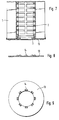
- the ring-shaped filter element in the embodiment according to FIG. 1, consists of a filter sheet 1 made of paper with a small amount of thermoplastic material and folded in a star shape.
- a tubular insert 2 made of plastic which passes axially through the entire filter element. This insert 2 represents a so-called plastic inner frame of the filter element.
- the end face of the filter element is sealed by a fleece 3 made of polyester, this polyester preferably being a polyethylene terephthalate.
- This fleece is connected to the front edges of the filter web by ultrasound welding, which is known per se.
- the fleece material projects radially inward beyond the tubular insert 2.
- a plastic ring 4 is welded onto the end edge of the tubular insert 2 by means of ultrasound via the fleece 3 as an intermediate layer.
- This plastic ring 4 has an L-shape on average. This ring serves to form a radially outer abutment for the radially inner part of the fleece 3 when the filter element is attached to a tube in the direction of arrow A.
- FIG. 1 shows an embodiment in which the filter element has to be pushed onto a continuous piece of pipe in the direction of arrow A
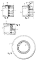
- FIG. 2 shows an embodiment in which the push-on direction for the filter element is indifferent. Because there is also the end region of the tubular insert 2 adjoining the plastic ring 4 such that the part of the fleece 3 projecting radially on the inside is chamber-like there between the insert 2 and the tube onto which the filter element is pushed, as can be seen in EP 0 559 011 A1.
- the plastic ring 5 welded on in the embodiment according to FIG. 3 serves to receive a sealing ring 6.
- the plastic ring 8 also serves to receive a sealing ring 7 in the embodiment according to FIG. 4.
- FIG. 5 also serves a little differently designed plastic ring 9 in turn for receiving a sealing ring 10.
- FIG. 6 A further alternative embodiment is shown in FIG. 6 with a plastic ring 11 and a sealing ring 12.
- a cover disk 13 made of solid, compact material is ultrasonically welded over the fleece 3 as an intermediate layer on the end edge of the tubular insert 2.
- the part of the fleece 3 protruding radially on the inside serves as a radial seal in the form already described several times above.
- the ultrasonic welding of the plastic rings 4, 5, 8, 9, 11 and the cover plate 13 takes place in each case via molded projections 14 (FIGS. 8, 9).
- the height of these projections 14 is selected such that, on the one hand, there is a secure welding to the tubular insert 2 and, on the other hand, the nonwoven material 3 lying between the projections 14 is sufficiently tightly braced but not yet welded.
- a cover plate 15 is firmly placed on the open end of a filter element.
- the cover plate 15 is provided with spikes 16 distributed over its circumference, which are firmly clamped through the fleece 3 into corresponding receptacles in the tubular insert part 2.
- the latching connection is designed such that the fleece 3 is tightly clamped between the cover plate 15 and the end face of the tubular insert 2, so that the cover plate closes the filter element tightly at the relevant end.
- other functional support parts can also be attached to the tubular insert 2 in the same way of the filter element are attached. This provides a replacement for a welded joint according to the previous exemplary embodiments.
- a plug 17 is snapped into the interior of the tubular insert part 2 by means of resilient feet 18 through the open end of a filter element.
- the plug 17 permits a tight closure of the open end of the filter element.
- the tightness is achieved in that an edge region of the fleece 3 projecting radially inward beyond the edge of the tubular insert 2 is used to form a radial seal between the plug 17 and the tubular insert 2.
- this protruding edge of the fleece is tightly pressed into a radial gap 19.
- any function carrier can also be used to hold any parts to be attached to the filter element.
- FIG. 12 An embodiment of an extremely simple and therefore inexpensive closure of an open end of a filter element is shown in FIG. 12.
- the tubular insert 2 has a closed end.
- the fleece 3 is simultaneously welded onto the end edges of the filter web 1 and the end face of the tubular insert 2 in an ultrasound process.
- the materials of the fleece 3 and the tubular insert 2 each contain at least thermoplastic or, like the fleece 3 and the tubular insert 2, are made entirely of such a material.
- the fleece 3 is made of thermoplastic polyester.
- the material of the filter web 1 is made of paper and contains small amounts of plastic resins.
- annular gap 20 is provided at this transition. This annular gap should have at least a radial extension of approximately 0.5 mm.
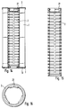
- a further, in particular additional, measure to avoid shearing off the fleece 3 on the radial outer edge of the tubular insert 2 is carried out by welding the fleece 3 to this tubular insert 2 in a grid-like manner (FIG. 13).
- Grid-shaped here means that there is no full-area welding on the end face of the insert 2, but rather only a grid-like or net-like welding in the nodes or lines of a surface network. In this way, elastic areas remain on the fleece 3, which prevent shearing at the radial outer edge of the tubular insert 2 during the transition to the filter web 1.
- the grid-shaped welding is achieved by using an ultrasonic welding sonotrode with, for example, a waffle-like grooved surface.
- the filter element according to FIG. 14 should consist entirely of thermally disposable material.
- a special feature of that filter element is that it should be rotatable at one end in a housing part.
- the filter element should be tightly closed at this end.
- the filter element should be able to be plugged radially tight onto a connecting piece extending from the filter housing. When inserted in a filter housing, the filter element is to be flowed through radially.
- the tubular insert 2 is provided at one end with a corresponding cup-shaped closure with collar sections 21 drawn inwards (FIGS. 15, 16). A latching on an annular counter-holder of the filter housing is possible via these sections.
- the usual designation for the tubular insert 2 in a filter element of this type is "plastic inner frame".
- annular fleece 3 is welded in the manner described in FIG. 12 in an ultrasonic process onto the end edges of the filter web material and the end face of the insert 2.
- the seal with respect to the connection piece onto which the filter element is to be placed is made by a radial seal which is formed at this end in a manner known per se by a folded inner region of the fleece 3.
- An annular cover disk 13 is applied to this end of the ring filter in an ultrasound process.
- the type of application corresponds that which is described in more detail in connection with FIGS. 8 and 9.
- the cover plate 13 is used in this filter element to be able to apply this axially to a valve via the cover plate. Without such a fixed cover plate, there would be a risk of the welded-on fleece 3 being destroyed at this end of the filter element.
- the use of fleece end disks enables a particularly cost-effective production of such a filter element.
Landscapes
- Chemical & Material Sciences (AREA)
- Chemical Kinetics & Catalysis (AREA)
- Physics & Mathematics (AREA)
- Geometry (AREA)
- Filtering Materials (AREA)
- Filtering Of Dispersed Particles In Gases (AREA)
- Filtration Of Liquid (AREA)
- Separation Using Semi-Permeable Membranes (AREA)
Applications Claiming Priority (2)
| Application Number | Priority Date | Filing Date | Title |
|---|---|---|---|
| DE4419361A DE4419361A1 (de) | 1994-06-03 | 1994-06-03 | Ringfilterelement mit stirnseitiger Vliesabdeckung |
| DE4419361 | 1994-06-03 |
Publications (2)
| Publication Number | Publication Date |
|---|---|
| EP0685251A1 true EP0685251A1 (fr) | 1995-12-06 |
| EP0685251B1 EP0685251B1 (fr) | 1998-08-12 |
Family
ID=6519664
Family Applications (1)
| Application Number | Title | Priority Date | Filing Date |
|---|---|---|---|
| EP95106585A Expired - Lifetime EP0685251B1 (fr) | 1994-06-03 | 1995-05-02 | Elément filtrant annulaire à couverture de non-tissé sur la face |
Country Status (3)
| Country | Link |
|---|---|
| EP (1) | EP0685251B1 (fr) |
| DE (2) | DE4419361A1 (fr) |
| ES (1) | ES2120658T3 (fr) |
Cited By (14)
| Publication number | Priority date | Publication date | Assignee | Title |
|---|---|---|---|---|
| EP0781586A3 (fr) * | 1995-12-27 | 1997-07-09 | Knecht Filterwerke Gmbh | Elément filtrant annulaire |
| WO1998005403A1 (fr) * | 1996-08-02 | 1998-02-12 | Filterwerk Mann+Hummel Gmbh | Tuyau central encliquete |
| WO2000000263A1 (fr) * | 1998-06-26 | 2000-01-06 | Pall Corporation | Element de filtration et procede de fabrication de cet element |
| EP0826566A3 (fr) * | 1996-08-28 | 2000-02-02 | Autoliv ASP, Inc. | Joint comportant une étiquette pour un boítier serti d'un gonfleur |
| WO2000018489A1 (fr) * | 1998-09-30 | 2000-04-06 | Mahle Filtersysteme Gmbh | Element de filtre a plaques |
| EP1163945A1 (fr) | 2000-06-17 | 2001-12-19 | Filterwerk Mann + Hummel Gmbh | Cartouche de filtre cylindrique avec tube de support |
| US6739459B1 (en) | 1998-06-26 | 2004-05-25 | Pall Corporation | Filter element including bonded end caps and support core |
| EP1424118A1 (fr) * | 2002-11-29 | 2004-06-02 | Mann+Hummel Gmbh | Elément filtrant liquide |
| DE102013017302A1 (de) * | 2013-10-18 | 2015-04-23 | Mann + Hummel Gmbh | Filteranordnung |
| DE10259900B4 (de) | 2002-12-20 | 2018-03-08 | Mann + Hummel Gmbh | Filterelement, Verfahren zu dessen Herstellung und Verwendung des Filterelements |
| EP3530337A1 (fr) * | 2018-02-27 | 2019-08-28 | Mahle Metal Leve S/A | Élément de pré-filtrage de carburant |
| WO2021021655A1 (fr) * | 2019-07-26 | 2021-02-04 | Donaldson Company, Inc. | Éléments filtrants et procédés de fabrication d'éléments filtrants |
| CN116379016A (zh) * | 2022-12-01 | 2023-07-04 | 鹤山市民强五金机电有限公司 | 一种具有清理过滤部件功能的换气风机 |
| US12311301B2 (en) | 2021-01-27 | 2025-05-27 | Donaldson Company, Inc. | Filter element and method of manufacturing a filter element |
Families Citing this family (9)
| Publication number | Priority date | Publication date | Assignee | Title |
|---|---|---|---|---|
| DE19541385A1 (de) * | 1995-11-07 | 1997-05-15 | Knecht Filterwerke Gmbh | Radial durchströmbares Ringfilterelement |
| DE19723580A1 (de) * | 1997-06-05 | 1998-12-10 | Knecht Filterwerke Gmbh | Filter für Gase und Flüssigkeiten |
| DE19727369A1 (de) * | 1997-06-27 | 1999-01-07 | Knecht Filterwerke Gmbh | Rohrförmiges Filterelement |
| WO1999019043A2 (fr) * | 1997-10-09 | 1999-04-22 | Pall Corporation | Elements filtrants et procede de fabrication |
| DE10152552A1 (de) * | 2001-10-24 | 2003-05-08 | Mann & Hummel Filter | Filterelement, insbesondere für die Filtrierung von Flüssigkeiten |
| DE102004025811A1 (de) * | 2004-05-05 | 2006-03-23 | Mann + Hummel Gmbh | Filterelement und Flüssigkeitsfilter für einfriergefährdete Fluide sowie Verfahren zur Herstellung des Filterelementes |
| DE102013011086A1 (de) | 2013-07-03 | 2015-01-08 | Mann + Hummel Gmbh | Filterelement und Verfahren zur Herstellung eines Filterelements |
| DE202019105409U1 (de) | 2019-09-30 | 2019-11-13 | Mahle International Gmbh | Ringfilterelement |
| DE102020121340B4 (de) | 2020-08-13 | 2023-10-26 | Mann+Hummel Gmbh | Filterelement und Filtereinrichtung |
Citations (3)
| Publication number | Priority date | Publication date | Assignee | Title |
|---|---|---|---|---|
| DE3837423A1 (de) * | 1988-11-04 | 1990-05-10 | Bosch Gmbh Robert | Fluessigkeitsfilter |
| DE4009246A1 (de) * | 1990-03-22 | 1991-09-26 | Knecht Filterwerke Gmbh | Filterelement aus einem zick-zack-foermig gefalteten, stern- oder plattenfoermig angeordneten filtermaterial |
| EP0559011A1 (fr) * | 1992-03-02 | 1993-09-08 | Knecht Filterwerke Gmbh | Elément filtrant annulaire ayant les extrémités couvertes d'un matériau d'étanchéité en forme plate ou de feuille |
Family Cites Families (13)
| Publication number | Priority date | Publication date | Assignee | Title |
|---|---|---|---|---|
| BE495750A (fr) * | 1949-05-20 | |||
| DE1767427U (de) * | 1957-05-29 | 1958-05-29 | Mann & Hummel Filter | Auswechselbare filterpatrone. |
| DE1924827U (de) * | 1965-07-30 | 1965-10-07 | Purolator Filter Gmbh | Ringwulst an gehaeusedeckel fuer oelfilter. |
| US3382984A (en) * | 1965-10-04 | 1968-05-14 | Kuss & Co R L | Filter construction |
| CA1080130A (fr) * | 1976-03-30 | 1980-06-24 | Pall Corporation | Filtre pharmaceutique |
| US4301012A (en) * | 1979-04-25 | 1981-11-17 | Purolator Technologies, Inc. | Welded stainless steel mesh cleanable filter |
| US4218324A (en) * | 1979-05-03 | 1980-08-19 | Textron, Inc. | Filter element having removable filter media member |
| US4464263A (en) * | 1980-09-02 | 1984-08-07 | Fram Corporation | Pleated filter element and integral shield and method for making same |
| GB8411912D0 (en) * | 1984-05-10 | 1984-06-13 | Vokes Ltd | Filters |
| DE3429634A1 (de) * | 1984-08-11 | 1986-02-20 | Ing. Walter Hengst GmbH & Co KG, 4400 Münster | Anschraubfilter fuer kraft- und/oder schmierstoffe |
| EP0217482A1 (fr) * | 1985-07-19 | 1987-04-08 | Hr Textron Inc. | Elément filtrant |
| EP0498757B2 (fr) * | 1991-02-08 | 1997-11-05 | Knecht Filterwerke Gmbh | Procédé pour la fabrication d'un filtre annulaire formé d'un matériau filtrant plié en forme d'etoile |
| DE4206519C2 (de) * | 1992-03-02 | 1998-07-02 | Knecht Filterwerke Gmbh | Ringfilterelement mit die Stirnseiten dicht abdeckendem platten- oder folienförmigen Dichtmaterial |
-
1994
- 1994-06-03 DE DE4419361A patent/DE4419361A1/de not_active Withdrawn
-
1995
- 1995-05-02 DE DE59503123T patent/DE59503123D1/de not_active Expired - Lifetime
- 1995-05-02 EP EP95106585A patent/EP0685251B1/fr not_active Expired - Lifetime
- 1995-05-02 ES ES95106585T patent/ES2120658T3/es not_active Expired - Lifetime
Patent Citations (3)
| Publication number | Priority date | Publication date | Assignee | Title |
|---|---|---|---|---|
| DE3837423A1 (de) * | 1988-11-04 | 1990-05-10 | Bosch Gmbh Robert | Fluessigkeitsfilter |
| DE4009246A1 (de) * | 1990-03-22 | 1991-09-26 | Knecht Filterwerke Gmbh | Filterelement aus einem zick-zack-foermig gefalteten, stern- oder plattenfoermig angeordneten filtermaterial |
| EP0559011A1 (fr) * | 1992-03-02 | 1993-09-08 | Knecht Filterwerke Gmbh | Elément filtrant annulaire ayant les extrémités couvertes d'un matériau d'étanchéité en forme plate ou de feuille |
Cited By (21)
| Publication number | Priority date | Publication date | Assignee | Title |
|---|---|---|---|---|
| EP0781586A3 (fr) * | 1995-12-27 | 1997-07-09 | Knecht Filterwerke Gmbh | Elément filtrant annulaire |
| WO1998005403A1 (fr) * | 1996-08-02 | 1998-02-12 | Filterwerk Mann+Hummel Gmbh | Tuyau central encliquete |
| EP0826566A3 (fr) * | 1996-08-28 | 2000-02-02 | Autoliv ASP, Inc. | Joint comportant une étiquette pour un boítier serti d'un gonfleur |
| WO2000000263A1 (fr) * | 1998-06-26 | 2000-01-06 | Pall Corporation | Element de filtration et procede de fabrication de cet element |
| US6739459B1 (en) | 1998-06-26 | 2004-05-25 | Pall Corporation | Filter element including bonded end caps and support core |
| WO2000018489A1 (fr) * | 1998-09-30 | 2000-04-06 | Mahle Filtersysteme Gmbh | Element de filtre a plaques |
| US6379438B1 (en) | 1998-09-30 | 2002-04-30 | Mahle Filtersysteme Gmbh | Plate filter element for an air filter |
| EP1163945A1 (fr) | 2000-06-17 | 2001-12-19 | Filterwerk Mann + Hummel Gmbh | Cartouche de filtre cylindrique avec tube de support |
| EP1163945B1 (fr) * | 2000-06-17 | 2009-04-29 | Mann + Hummel GmbH | Cartouche de filtre cylindrique avec tube de support |
| EP1424118A1 (fr) * | 2002-11-29 | 2004-06-02 | Mann+Hummel Gmbh | Elément filtrant liquide |
| EP1424118B1 (fr) | 2002-11-29 | 2016-04-27 | MANN+HUMMEL GmbH | Elément filtrant liquide |
| DE10259900B4 (de) | 2002-12-20 | 2018-03-08 | Mann + Hummel Gmbh | Filterelement, Verfahren zu dessen Herstellung und Verwendung des Filterelements |
| DE102013017302A1 (de) * | 2013-10-18 | 2015-04-23 | Mann + Hummel Gmbh | Filteranordnung |
| DE102013017302B4 (de) | 2013-10-18 | 2019-03-14 | Mann+Hummel Gmbh | Filteranordnung |
| EP3530337A1 (fr) * | 2018-02-27 | 2019-08-28 | Mahle Metal Leve S/A | Élément de pré-filtrage de carburant |
| US11007459B2 (en) | 2018-02-27 | 2021-05-18 | Mahle International Gmbh | Fuel pre-filtering element |
| WO2021021655A1 (fr) * | 2019-07-26 | 2021-02-04 | Donaldson Company, Inc. | Éléments filtrants et procédés de fabrication d'éléments filtrants |
| CN114555209A (zh) * | 2019-07-26 | 2022-05-27 | 唐纳森公司 | 过滤器元件和制造过滤器元件的方法 |
| US12337270B2 (en) | 2019-07-26 | 2025-06-24 | Donaldson Company, Inc. | Filter elements and methods of manufacturing filter elements |
| US12311301B2 (en) | 2021-01-27 | 2025-05-27 | Donaldson Company, Inc. | Filter element and method of manufacturing a filter element |
| CN116379016A (zh) * | 2022-12-01 | 2023-07-04 | 鹤山市民强五金机电有限公司 | 一种具有清理过滤部件功能的换气风机 |
Also Published As
| Publication number | Publication date |
|---|---|
| EP0685251B1 (fr) | 1998-08-12 |
| DE4419361A1 (de) | 1995-12-07 |
| ES2120658T3 (es) | 1998-11-01 |
| DE59503123D1 (de) | 1998-09-17 |
Similar Documents
| Publication | Publication Date | Title |
|---|---|---|
| EP0685251B1 (fr) | Elément filtrant annulaire à couverture de non-tissé sur la face | |
| EP0897317B1 (fr) | Disque terminal pour element filtrant annulaire a joint agissant radialement | |
| DE69201671T2 (de) | Abdichtaufsätze für Filterelemente. | |
| DE69503477T2 (de) | Membranträger und abdichtungsvorrichtung | |
| EP0559011B1 (fr) | Elément filtrant annulaire ayant les extrémités couvertes d'un matériau d'étanchéité en forme plate ou de feuille | |
| DE60133449T2 (de) | Fluidfilter und ein Fluidfilter-Filterkopf-Gerät | |
| DE4416577C2 (de) | Filtereinsatz für ein Filter zur Filterung von flüssigen oder gasförmigen Medien | |
| EP0912225A1 (fr) | Disque, en particulier disque frontal, d'une cartouche filtrante | |
| EP0650751A2 (fr) | Appareil pour filtrer | |
| DE2845602A1 (de) | Verfahren zur herstellung einer verbindung zwischen verschlossenen leitungen und verbindungsstueck dafuer | |
| EP0773052B1 (fr) | Elément filtrant annulaire traversé radialement | |
| EP1137473A1 (fr) | Ensemble cartouche filtrante | |
| WO2007085427A1 (fr) | Element de filtre dote d'un element de raccordement | |
| DE4206519C2 (de) | Ringfilterelement mit die Stirnseiten dicht abdeckendem platten- oder folienförmigen Dichtmaterial | |
| EP0317903A1 (fr) | Joint annulaire | |
| DE10301843B4 (de) | Filter | |
| DE3000013A1 (de) | Fluessigkeitsfilter | |
| DE4419360C1 (de) | Ringfilterelement | |
| DE19850423C2 (de) | Kugelgelenk | |
| DE102014000597A1 (de) | Flüssigkeitsfilter | |
| WO1996036414A1 (fr) | Agencement de filtrage | |
| DE4225144A1 (de) | Ringfilterelement mit die Stirnseiten dicht abdeckendem platten- oder folienförmigem Dichtmaterial | |
| DE9403868U1 (de) | Filtereinsatz, insbesondere für Öl- oder Kraftstoffilter | |
| EP1695751A1 (fr) | Capuchon d'extrémité en matière plastique | |
| DE19731766B4 (de) | Flaches Plattenfilter aus zick-zack-förmig gefaltetem Filterbahnmaterial und flaches Filtergehäuse mit einem solchen Plattenfilter |
Legal Events
| Date | Code | Title | Description |
|---|---|---|---|
| PUAI | Public reference made under article 153(3) epc to a published international application that has entered the european phase |
Free format text: ORIGINAL CODE: 0009012 |
|
| 17P | Request for examination filed |
Effective date: 19950929 |
|
| AK | Designated contracting states |
Kind code of ref document: A1 Designated state(s): DE ES FR GB IT |
|
| 17Q | First examination report despatched |
Effective date: 19961216 |
|
| GRAG | Despatch of communication of intention to grant |
Free format text: ORIGINAL CODE: EPIDOS AGRA |
|
| GRAG | Despatch of communication of intention to grant |
Free format text: ORIGINAL CODE: EPIDOS AGRA |
|
| GRAH | Despatch of communication of intention to grant a patent |
Free format text: ORIGINAL CODE: EPIDOS IGRA |
|
| GRAH | Despatch of communication of intention to grant a patent |
Free format text: ORIGINAL CODE: EPIDOS IGRA |
|
| GRAA | (expected) grant |
Free format text: ORIGINAL CODE: 0009210 |
|
| AK | Designated contracting states |
Kind code of ref document: B1 Designated state(s): DE ES FR GB IT |
|
| PG25 | Lapsed in a contracting state [announced via postgrant information from national office to epo] |
Ref country code: IT Free format text: LAPSE BECAUSE OF FAILURE TO SUBMIT A TRANSLATION OF THE DESCRIPTION OR TO PAY THE FEE WITHIN THE PRE;WARNING: LAPSES OF ITALIAN PATENTS WITH EFFECTIVE DATE BEFORE 2007 MAY HAVE OCCURRED AT ANY TIME BEFORE 2007. THE CORRECT EFFECTIVE DATE MAY BE DIFFERENT FROM THE ONE RECORDED.SCRIBED TIME-LIMIT Effective date: 19980812 |
|
| REF | Corresponds to: |
Ref document number: 59503123 Country of ref document: DE Date of ref document: 19980917 |
|
| GBT | Gb: translation of ep patent filed (gb section 77(6)(a)/1977) |
Effective date: 19980828 |
|
| REG | Reference to a national code |
Ref country code: ES Ref legal event code: FG2A Ref document number: 2120658 Country of ref document: ES Kind code of ref document: T3 |
|
| ET | Fr: translation filed | ||
| PLBE | No opposition filed within time limit |
Free format text: ORIGINAL CODE: 0009261 |
|
| STAA | Information on the status of an ep patent application or granted ep patent |
Free format text: STATUS: NO OPPOSITION FILED WITHIN TIME LIMIT |
|
| 26N | No opposition filed | ||
| REG | Reference to a national code |
Ref country code: GB Ref legal event code: IF02 |
|
| PGFP | Annual fee paid to national office [announced via postgrant information from national office to epo] |
Ref country code: GB Payment date: 20140530 Year of fee payment: 20 |
|
| PGFP | Annual fee paid to national office [announced via postgrant information from national office to epo] |
Ref country code: ES Payment date: 20140623 Year of fee payment: 20 |
|
| PGFP | Annual fee paid to national office [announced via postgrant information from national office to epo] |
Ref country code: DE Payment date: 20140731 Year of fee payment: 20 |
|
| PGFP | Annual fee paid to national office [announced via postgrant information from national office to epo] |
Ref country code: FR Payment date: 20140528 Year of fee payment: 20 |
|
| REG | Reference to a national code |
Ref country code: DE Ref legal event code: R071 Ref document number: 59503123 Country of ref document: DE |
|
| REG | Reference to a national code |
Ref country code: GB Ref legal event code: PE20 Expiry date: 20150501 |
|
| REG | Reference to a national code |
Ref country code: ES Ref legal event code: FD2A Effective date: 20150724 |
|
| PG25 | Lapsed in a contracting state [announced via postgrant information from national office to epo] |
Ref country code: GB Free format text: LAPSE BECAUSE OF EXPIRATION OF PROTECTION Effective date: 20150501 |
|
| PG25 | Lapsed in a contracting state [announced via postgrant information from national office to epo] |
Ref country code: ES Free format text: LAPSE BECAUSE OF EXPIRATION OF PROTECTION Effective date: 20150503 |