EP0685251B1 - Elément filtrant annulaire à couverture de non-tissé sur la face - Google Patents
Elément filtrant annulaire à couverture de non-tissé sur la face Download PDFInfo
- Publication number
- EP0685251B1 EP0685251B1 EP95106585A EP95106585A EP0685251B1 EP 0685251 B1 EP0685251 B1 EP 0685251B1 EP 95106585 A EP95106585 A EP 95106585A EP 95106585 A EP95106585 A EP 95106585A EP 0685251 B1 EP0685251 B1 EP 0685251B1
- Authority
- EP
- European Patent Office
- Prior art keywords
- filter element
- annular
- add
- tubular insert
- element according
- Prior art date
- Legal status (The legal status is an assumption and is not a legal conclusion. Google has not performed a legal analysis and makes no representation as to the accuracy of the status listed.)
- Expired - Lifetime
Links
- 239000004745 nonwoven fabric Substances 0.000 title 1
- 239000000463 material Substances 0.000 claims description 30
- 239000004033 plastic Substances 0.000 claims description 30
- 229920003023 plastic Polymers 0.000 claims description 30
- 238000003466 welding Methods 0.000 claims description 21
- 229920001169 thermoplastic Polymers 0.000 claims description 4
- 239000012815 thermoplastic material Substances 0.000 claims description 4
- 239000011343 solid material Substances 0.000 claims description 2
- 230000000284 resting effect Effects 0.000 claims 1
- 238000000034 method Methods 0.000 description 7
- 238000007789 sealing Methods 0.000 description 6
- 229920000728 polyester Polymers 0.000 description 5
- 230000007704 transition Effects 0.000 description 4
- 238000002604 ultrasonography Methods 0.000 description 3
- 238000004519 manufacturing process Methods 0.000 description 2
- 239000007787 solid Substances 0.000 description 2
- 239000004416 thermosoftening plastic Substances 0.000 description 2
- 230000015572 biosynthetic process Effects 0.000 description 1
- 238000002485 combustion reaction Methods 0.000 description 1
- 230000006835 compression Effects 0.000 description 1
- 238000007906 compression Methods 0.000 description 1
- 230000001419 dependent effect Effects 0.000 description 1
- -1 polyethylene terephthalate Polymers 0.000 description 1
- 229920000139 polyethylene terephthalate Polymers 0.000 description 1
- 239000005020 polyethylene terephthalate Substances 0.000 description 1
- 229920005989 resin Polymers 0.000 description 1
- 239000011347 resin Substances 0.000 description 1
- 238000010008 shearing Methods 0.000 description 1
Images


Classifications
-
- B—PERFORMING OPERATIONS; TRANSPORTING
- B01—PHYSICAL OR CHEMICAL PROCESSES OR APPARATUS IN GENERAL
- B01D—SEPARATION
- B01D46/00—Filters or filtering processes specially modified for separating dispersed particles from gases or vapours
- B01D46/24—Particle separators, e.g. dust precipitators, using rigid hollow filter bodies
- B01D46/2403—Particle separators, e.g. dust precipitators, using rigid hollow filter bodies characterised by the physical shape or structure of the filtering element
- B01D46/2411—Filter cartridges
-
- B—PERFORMING OPERATIONS; TRANSPORTING
- B01—PHYSICAL OR CHEMICAL PROCESSES OR APPARATUS IN GENERAL
- B01D—SEPARATION
- B01D29/00—Filters with filtering elements stationary during filtration, e.g. pressure or suction filters, not covered by groups B01D24/00 - B01D27/00; Filtering elements therefor
- B01D29/11—Filters with filtering elements stationary during filtration, e.g. pressure or suction filters, not covered by groups B01D24/00 - B01D27/00; Filtering elements therefor with bag, cage, hose, tube, sleeve or like filtering elements
- B01D29/111—Making filtering elements
-
- B—PERFORMING OPERATIONS; TRANSPORTING
- B01—PHYSICAL OR CHEMICAL PROCESSES OR APPARATUS IN GENERAL
- B01D—SEPARATION
- B01D29/00—Filters with filtering elements stationary during filtration, e.g. pressure or suction filters, not covered by groups B01D24/00 - B01D27/00; Filtering elements therefor
- B01D29/11—Filters with filtering elements stationary during filtration, e.g. pressure or suction filters, not covered by groups B01D24/00 - B01D27/00; Filtering elements therefor with bag, cage, hose, tube, sleeve or like filtering elements
- B01D29/13—Supported filter elements
- B01D29/15—Supported filter elements arranged for inward flow filtration
- B01D29/21—Supported filter elements arranged for inward flow filtration with corrugated, folded or wound sheets
-
- B—PERFORMING OPERATIONS; TRANSPORTING
- B01—PHYSICAL OR CHEMICAL PROCESSES OR APPARATUS IN GENERAL
- B01D—SEPARATION
- B01D29/00—Filters with filtering elements stationary during filtration, e.g. pressure or suction filters, not covered by groups B01D24/00 - B01D27/00; Filtering elements therefor
- B01D29/96—Filters with filtering elements stationary during filtration, e.g. pressure or suction filters, not covered by groups B01D24/00 - B01D27/00; Filtering elements therefor in which the filtering elements are moved between filtering operations; Particular measures for removing or replacing the filtering elements; Transport systems for filters
-
- B—PERFORMING OPERATIONS; TRANSPORTING
- B01—PHYSICAL OR CHEMICAL PROCESSES OR APPARATUS IN GENERAL
- B01D—SEPARATION
- B01D46/00—Filters or filtering processes specially modified for separating dispersed particles from gases or vapours
- B01D46/52—Particle separators, e.g. dust precipitators, using filters embodying folded corrugated or wound sheet material
- B01D46/521—Particle separators, e.g. dust precipitators, using filters embodying folded corrugated or wound sheet material using folded, pleated material
-
- B—PERFORMING OPERATIONS; TRANSPORTING
- B01—PHYSICAL OR CHEMICAL PROCESSES OR APPARATUS IN GENERAL
- B01D—SEPARATION
- B01D2201/00—Details relating to filtering apparatus
- B01D2201/04—Supports for the filtering elements
- B01D2201/0415—Details of supporting structures
-
- B—PERFORMING OPERATIONS; TRANSPORTING
- B01—PHYSICAL OR CHEMICAL PROCESSES OR APPARATUS IN GENERAL
- B01D—SEPARATION
- B01D2201/00—Details relating to filtering apparatus
- B01D2201/29—Filter cartridge constructions
- B01D2201/291—End caps
-
- B—PERFORMING OPERATIONS; TRANSPORTING
- B01—PHYSICAL OR CHEMICAL PROCESSES OR APPARATUS IN GENERAL
- B01D—SEPARATION
- B01D2201/00—Details relating to filtering apparatus
- B01D2201/34—Seals or gaskets for filtering elements
-
- B—PERFORMING OPERATIONS; TRANSPORTING
- B01—PHYSICAL OR CHEMICAL PROCESSES OR APPARATUS IN GENERAL
- B01D—SEPARATION
- B01D2201/00—Details relating to filtering apparatus
- B01D2201/40—Special measures for connecting different parts of the filter
- B01D2201/4084—Snap or Seeger ring connecting means
-
- B—PERFORMING OPERATIONS; TRANSPORTING
- B01—PHYSICAL OR CHEMICAL PROCESSES OR APPARATUS IN GENERAL
- B01D—SEPARATION
- B01D2265/00—Casings, housings or mounting for filters specially adapted for separating dispersed particles from gases or vapours
- B01D2265/04—Permanent measures for connecting different parts of the filter, e.g. welding, glueing or moulding
-
- B—PERFORMING OPERATIONS; TRANSPORTING
- B01—PHYSICAL OR CHEMICAL PROCESSES OR APPARATUS IN GENERAL
- B01D—SEPARATION
- B01D2265/00—Casings, housings or mounting for filters specially adapted for separating dispersed particles from gases or vapours
- B01D2265/06—Details of supporting structures for filtering material, e.g. cores
Definitions
- the invention relates to a ring filter element according to the preamble of claim 1.
- Such a ring filter element is known from EP-A-0 559 011 A1.
- the front seal of such a filter element with a fleece made of thermoplastic material that For example, polyester can be extremely inexpensive can be produced by connecting the fleece to the Filter web material generated by ultrasonic welding see DE-A-4 009 246.
- the fleece cover protrudes each radially inside into the free ring filter center slightly into it. It is in the center of the ring filter element at least in the area of the front ends arranged axially inside the ring filter element, where the fleece area protrudes radially inwards is present.
- the ring filter element is placed centrally on cylindrical tube plugged on, so it lies radially on the inside projecting area of the fleece to the axially adjacent Ring and can be used as a seal between the front Cover the filter element and the pipe that it is put on hold.
- the effectiveness of the solution according to claim 1 is based on that in this way also compact, rigid compared to the fleece Plastic parts on the End faces of the filter element by ultrasonic welding can be attached. This is done in such a way that a ring-shaped one in a first ultrasonic welding process Nonwoven us thermoplastic material is applied.
- the fixed compact to be attached to the front Plastic part is made in a second ultrasonic welding process attached. This attachment happens because that Plastic part over the fleece only with the under the non-woven tubular insert of the filter element, which can be a plastic inner frame, welded becomes.
- the welded joint can be read off particularly advantageously the character of claim 1 by training the Reach contact surface of the plastic part according to claim 2.
- the fleece material is pressed tightly.
- the height of the projections should be such that, on the one hand no welding has yet taken place in the gaps and that on the other hand a sufficiently tight compression of the Nonwoven material is given.
- the plastic part to be applied on the front can, for example be a flat washer.
- a washer solid compact material may be desirable if the filter element on the relevant end face, for example against a locally attacking valve that the fleece material in the case of relative movements between the filter element and could destroy the valve.
- the plastic part to be applied can be according to claim 4 Plastic ring.
- a ring is required, for example, if a filter element is one-sided on a pipe is plugged against which both end faces are sealed radially should be and such a seal by itself radially pressed nonwoven material is to be generated.
- the Fleece is between the tubular insert and tightly clamped to the additional part. That way for example, the filter element is sealed at one end will. But it can also only be an annular disc applied as an axial outer cover of the fleece will.
- the additional Part also on a centrally provided in the filter element tubular insert part locked. This latching does not occur through the fleece cover through it.
- the seal between the central insert and the additional part is rather done in this case by providing an annular gap between the insert part and the additional part in which the inner edge of the fleece cover is radially tightly clamped.
- the snapped Additional part can thus the relevant end of the filter element close tightly.
- This additional part can also serve as a functional part. For example, it can be used, a snap lock between the filter element and to produce a surrounding housing part.
- the fleece cover at the same time with the front edges of the zigzag folded Filter sheet material and the end face of an in the filter element centrally provided tubular insert ultrasonically welded.
- the one after the characteristic Part of this claim provided annular gap between the front edges of the filter web material and the ring web of the central insert is simultaneous Ultrasonic welding connection of the fleece cover with the Filter sheet material and the insert part required so the fleece during ultrasonic welding at the radial transition from the filter sheet material to the central insert is not sheared off. To avoid such shear is in particular the measure according to claim 13 really important.
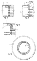
- annular filter element there is the annular filter element, only one end area of which is shown is, from a filter sheet 1 folded in a star shape made of paper with low proportions of thermoplastic Plastic.
- a filter sheet 1 folded in a star shape made of paper with low proportions of thermoplastic Plastic.
- Insert 2 made of plastic.
- This insert 2 represents a so-called plastic inner frame of the filter element represents.
- the end face of the filter element is sealed by a Fleece 3 made of polyester, this polyester preferably is a polyethylene terephthalate.
- This fleece is connected with the front edges of the filter web by known Ultrasonic welding. The fleece material protrudes radially on the inside beyond the tubular insert 2.
- a plastic ring 4 by means of ultrasound welded on.
- This plastic ring 4 has Cut an L shape. This ring serves a radially outside lying abutment for the radially inner Form part of the fleece 3 when the filter element in Direction of arrow A is placed on a pipe.
- FIG. 1 shows an embodiment in which the filter element in the direction of arrow A on a continuous 2 has to be pushed on
- FIG Version in which the opening direction for the filter element is indifferent. Because there is also the on Plastic ring 4 adjacent end portion of the tubular Insert 2 designed so that the radially projecting inside Part of the fleece 3 there like a chamber between the insert 2 and the pipe on which the filter element is pushed, is compressible, as described in EP 0 559 011 A1.
- the plastic ring welded on in the embodiment according to FIG. 3 5 serves to receive a sealing ring 6.
- the plastic ring also serves to receive a sealing ring 7 8 in the embodiment according to FIG. 4.
- FIG. 5 also serves a little differently designed plastic ring 9 in turn for receiving a Sealing ring 10.
- FIG. 6 shows Fig. 6 with a plastic ring 11 and a sealing ring 12th
- a cover plate 13 made of solid compact Material over the fleece 3 as an intermediate layer on the front edge the tubular insert 2 is ultrasonically welded on.
- the radially inner part of the fleece 3 serves in a bent form again in the above repeatedly described form as a radial seal.
- a cover plate 15 is on the open end of a filter element is firmly attached.
- the cover plate 15 with distributed over their circumference thorns 16 provided by the fleece 3 in corresponding recordings in the tubular insert 2 are firmly clamped.
- the rest connection is designed such that the fleece 3 between the cover plate 15 and the end face of the tubular insert 2 is tightly clamped so that the cover plate the filter element closes tightly at the relevant end.
- the cover plate can also other function carrier parts in the same way on the tubular insert 2 of the filter element are attached. This is a Replacement for a welded joint according to the previous ones Given embodiments.
- a plug 17 is through the open end of a filter element inside the tubular insert 2 snapped over resilient feet 18.
- the plug is 17th a tight seal of the open end of the filter element possible.
- the tightness is achieved in that a radial protruding inside over the edge of the tubular insert 2 Edge area of the fleece 3 to form a radial seal between the plug 17 and the tubular insert 2 are used becomes. For this purpose, this is the outstanding edge the fleece tightly pressed into a radial gap 19.
- any one Function carrier for receiving any on the filter element serve parts to be attached.
- FIG. Owns there the tubular insert 2 has a closed end.
- the Fleece 3 is simultaneously on the front edges of the filter web 1 and the end face of the tubular insert 2 in the ultrasound process welded on.
- the materials of the fleece 3 and the tubular insert 2 each contain at least thermoplastic or are like the fleece 3 and the tubular insert 2 completely from such Material.
- the fleece 3 is made of thermoplastic polyester.
- the material of the filter web 1 is made of paper and contains small proportions of plastic resins.
- This annular gap should be at least one radial Have an extension of about 0.5 mm.
- Another, especially additional, measure to avoid a shearing off of the fleece 3 on the radial outer edge the tubular insert 2 is made by welding of the fleece 3 on this tubular insert 2 grid-shaped (Fig. 13).
- Grid-shaped here means that there is no full-surface welding on the end face the insert 2 takes place, but rather only a grid or net-like welding in the nodes or lines of an area network.
- the grid-shaped Welding is done using an ultrasonic welding sonotrode with a waffle-like one, for example grooved surface achieved.
- the filter element according to FIG. 14 is intended exclusively consist of thermally disposable material.
- a special feature of that filter element is that it can be rotatably latched into a housing part at one end should. At this end, the filter element should be tightly closed be.
- the filter element At the other axial end of the filter element that should Filter element radially tight on one of the filter housing outgoing connector can be plugged. In a filter housing used condition, the filter element should be radial be flowed through.
- tubular insert 2 is opposite the filter housing 2 at one end with a corresponding pot-shaped Closure with inwardly drawn collar sections 21 (Fig. 15, 16). Is about these sections a latching on an annular counter holder of the Filter housing possible.
- the one with a filter element The usual name for the tubular insert 2 is "Plastic inner frame".
- annular fleece 3 At the cup-shaped end of the insert part 2 is an annular fleece 3 in that described in FIG. 12 Way in the ultrasound process at the same time Front edges of the filter web material and the front ring surface the insert 2 is welded on.
- the seal is made at the other end of the filter element opposite the nozzle on which the filter element is to be attached is, by a radial seal that is folded over Inner area of the fleece 3 at this end in is formed in a known manner.
- On this end of the Ring filter is a ring-shaped in the ultrasonic process Cover plate 13 applied.
- the type of application corresponds of those in connection with FIGS. 8 and 9 is described in more detail.
- the cover plate 13 serves this filter element to this axially over the cover plate to be able to put on a valve. Without such a firm Cover plate there is a risk of destroying the welded Fleece 3 at this end of the filter element. Due to the use of fleece end plates, one is special inexpensive manufacture of such a filter element possible.
Landscapes
- Chemical & Material Sciences (AREA)
- Chemical Kinetics & Catalysis (AREA)
- Physics & Mathematics (AREA)
- Geometry (AREA)
- Filtering Materials (AREA)
- Filtering Of Dispersed Particles In Gases (AREA)
- Filtration Of Liquid (AREA)
- Separation Using Semi-Permeable Membranes (AREA)
Claims (14)
- Elément filtrant annulaire pour une traversée radiale dans un matériau filtrant disposé de façon annulaire, en particulier un matériau de bande filtrante plié en zigzag, avec une couverture de non-tissé installée de façon dense par soudage par ultrasons sur au moins l'une des faces et réalisée au moins partiellement en matérieau thermoplastique, qui recouvre dans sa zone intérieure radiale la surface annulaire frontale d'un intercalaire tubulaire prévu au centre du filtre annulaire, en particulier d'un châssis interne en plastique, caractérisé en ce qu'une pièce supplémentaire (4, 5, 8, 9, 11, 13) axialement extérieure dans un matériau compact et rigide en comparaison de la couverture de non-tissé, qui contient au moins une partie de plastique thermoplastique, est soudée au-dessus du non-tissé (3) comme couche intermédiaire avec l'intercalaire tubulaire (2).
- Elément filtrant annulaire selon la revendication 1, caractérisé en ce que le soudage est un soudage par ultrasons.
- Elément filtrant annulaire selon la revendication 1 ou 2, caractérisé en ce que la pièce supplémentaire soudée (4, 5, 8, 9, 11, 13) possède des saillies (14) de type boutons disposées localement sur la surface frontale de l'intercalaire tubulaire (2) et en ce que la liaison soudée relativement à l'intercalaire tubulaire (2) est réalisée uniquement via ces saillies (14), pendant que le non-tissé (3) est comprimé de façon dense dans les zones situées de façon périphérique entre les saillies (14) entre la pièce supplémentaire soudée (4, 5, 8, 9, 11, 13) et la surface frontale de l'intercalaire tubulaire (2).
- Elément filtrant annulaire selon l'une des revendications précédentes, caractérisé en ce que la pièce supplémentaire soudée est une plaque annulaire (13).
- Elément filtrant annulaire selon l'une des revendications 1 à 3, caractérisé en ce que la pièce supplémentaire soudée est une bague (4) ayant un diamètre intérieur qui est mesuré de telle manière qu'un bord du non-tissé (3) débordant radialement vers l'intérieur, en reposant contre le contour intérieur de cette bague (4), puisse faire office de joint d'étanchéité relativement à une pièce cylindrique introduite dans cette bague (4).
- Elément filtrant annulaire selon l'une des revendications 1 à 3, caractérise en ce que la pièce supplémentaire soudée (5, 8, 9, 11) est un support pour joints de plaques terminales radiaux ou à action axiale de l'élément filtrant.
- Elément filtrant annulaire selon le préambule de la revendication 1, caractérisé en ce qu'une pièce supplémentaire (15) axialement extérieure repose sur la couverture de non-tissé et qu'elle s'enclenche avec l'intercalaire tubulaire (2) ou se coince dans celui-ci via des broches (16) partant de celle-ci au travers du non-tissé (3).
- Elément filtrant annulaire selon la revendication 7, caractérisé en ce que cette pièce supplémentaire (15) est une plaque annulaire.
- Elément filtrant annulaire selon le préambule de la revendication 1, caractérisé en ce que par au moins l'une des extrémités ouvertes de l'élément filtrant une pièce supplémentaire (17) s'enclenche ou se coince dans le contour intérieur de l'intercalaire tubulaire (2), et en ce que cette pièce supplémentaire (17) possède au moins une zone extérieure cylindrique, qui avec une zone également cylindrique de l'intercalaire tubulaire (2) disposée de façon radiale forme une fente annulaire (19) limitée axialement, dans laquelle le bord intérieur du non-tissé (3) peut être serré hermétiquement.
- Elément filtrant annulaire selon la revendication 7 ou 9, caractérisé en ce que la pièce supplémentaire enclenchée (15, 17) ferme hermétiquement l'extrémité ouverte concernée de l'élément filtrant.
- Elément filtrant annulaire selon la revendication 9 ou 10, caractérisé en ce que la pièce supplémentaire enclenchée (15, 17) est conçue pour une liaison à cran d'arrêt ou à encliquetage de l'élément filtrant sur une partie enveloppe entourant l'élément filtrant.
- Elément filtrant annulaire selon l'une des revendications précédentes, caractérisé en ce que la couverture de non-tissé (3) est soudée par ultrasons simultanément avec les bords frontaux ou surfaces frontales du matériau de bande filtrante (1) et l'intercalaire tubulaire (2), et en ce que, entre la surface frontale de l'intercalaire tubulaire (2) et le contour intérieur des bords frontaux du matériau de la bande filtrante (1), il est prévu une fente annulaire (20) limitée axialement.
- Elément filtrant annulaire selon la revendication 12, caractérisé en ce que l'extension radiale de la fente annulaire (20) est au moins égale à environ 0,5 mm.
- Elément filtrant annulaire selon la revendication 12 ou 13, caractérisé en ce que la couverture de non-tissé (3) est soudée à la façon d'une trame avec la surface annulaire frontale de l'intercalaire tubulaire (2).
Applications Claiming Priority (2)
| Application Number | Priority Date | Filing Date | Title |
|---|---|---|---|
| DE4419361A DE4419361A1 (de) | 1994-06-03 | 1994-06-03 | Ringfilterelement mit stirnseitiger Vliesabdeckung |
| DE4419361 | 1994-06-03 |
Publications (2)
| Publication Number | Publication Date |
|---|---|
| EP0685251A1 EP0685251A1 (fr) | 1995-12-06 |
| EP0685251B1 true EP0685251B1 (fr) | 1998-08-12 |
Family
ID=6519664
Family Applications (1)
| Application Number | Title | Priority Date | Filing Date |
|---|---|---|---|
| EP95106585A Expired - Lifetime EP0685251B1 (fr) | 1994-06-03 | 1995-05-02 | Elément filtrant annulaire à couverture de non-tissé sur la face |
Country Status (3)
| Country | Link |
|---|---|
| EP (1) | EP0685251B1 (fr) |
| DE (2) | DE4419361A1 (fr) |
| ES (1) | ES2120658T3 (fr) |
Cited By (2)
| Publication number | Priority date | Publication date | Assignee | Title |
|---|---|---|---|---|
| DE202019105409U1 (de) | 2019-09-30 | 2019-11-13 | Mahle International Gmbh | Ringfilterelement |
| DE102020121340A1 (de) | 2020-08-13 | 2022-02-17 | Mann+Hummel Gmbh | Filterelement und Filtereinrichtung |
Families Citing this family (21)
| Publication number | Priority date | Publication date | Assignee | Title |
|---|---|---|---|---|
| DE19541385A1 (de) * | 1995-11-07 | 1997-05-15 | Knecht Filterwerke Gmbh | Radial durchströmbares Ringfilterelement |
| DE19548864A1 (de) * | 1995-12-27 | 1997-07-03 | Knecht Filterwerke Gmbh | Ringfiltereinsatz |
| DE19631278A1 (de) * | 1996-08-02 | 1998-02-05 | Mann & Hummel Filter | Verschnapptes Mittelrohr |
| US5797624A (en) * | 1996-08-28 | 1998-08-25 | Morton International, Inc. | Integral label/gasket for crimped inflator housing |
| DE19723580A1 (de) * | 1997-06-05 | 1998-12-10 | Knecht Filterwerke Gmbh | Filter für Gase und Flüssigkeiten |
| DE19727369A1 (de) * | 1997-06-27 | 1999-01-07 | Knecht Filterwerke Gmbh | Rohrförmiges Filterelement |
| WO1999019043A2 (fr) * | 1997-10-09 | 1999-04-22 | Pall Corporation | Elements filtrants et procede de fabrication |
| KR20010034915A (ko) * | 1998-06-26 | 2001-04-25 | 와이너 길버트 피. | 필터 엘리먼트 및 필터 엘리먼트의 제조방법 |
| US6739459B1 (en) | 1998-06-26 | 2004-05-25 | Pall Corporation | Filter element including bonded end caps and support core |
| DE19844874A1 (de) * | 1998-09-30 | 2000-04-06 | Knecht Filterwerke Gmbh | Plattenfilterelement für ein Luftfilter |
| DE10030037A1 (de) | 2000-06-17 | 2001-12-20 | Mann & Hummel Filter | Zylindrische Filterpatrone mit Stützrohr |
| DE10152552A1 (de) * | 2001-10-24 | 2003-05-08 | Mann & Hummel Filter | Filterelement, insbesondere für die Filtrierung von Flüssigkeiten |
| DE10255701A1 (de) * | 2002-11-29 | 2004-06-17 | Mann + Hummel Gmbh | Flüssigkeitsfilterelement |
| DE10259900B4 (de) | 2002-12-20 | 2018-03-08 | Mann + Hummel Gmbh | Filterelement, Verfahren zu dessen Herstellung und Verwendung des Filterelements |
| DE102004025811A1 (de) * | 2004-05-05 | 2006-03-23 | Mann + Hummel Gmbh | Filterelement und Flüssigkeitsfilter für einfriergefährdete Fluide sowie Verfahren zur Herstellung des Filterelementes |
| DE102013011086A1 (de) | 2013-07-03 | 2015-01-08 | Mann + Hummel Gmbh | Filterelement und Verfahren zur Herstellung eines Filterelements |
| DE102013017302B4 (de) * | 2013-10-18 | 2019-03-14 | Mann+Hummel Gmbh | Filteranordnung |
| EP3530337A1 (fr) * | 2018-02-27 | 2019-08-28 | Mahle Metal Leve S/A | Élément de pré-filtrage de carburant |
| US12337270B2 (en) | 2019-07-26 | 2025-06-24 | Donaldson Company, Inc. | Filter elements and methods of manufacturing filter elements |
| EP4035757A1 (fr) | 2021-01-27 | 2022-08-03 | Donaldson Company, Inc. | Élément de filtre et procédé de fabrication d'un élément de filtre |
| CN115788975B (zh) * | 2022-12-01 | 2023-06-06 | 鹤山市民强五金机电有限公司 | 一种管风式室内换气风机及方法 |
Family Cites Families (16)
| Publication number | Priority date | Publication date | Assignee | Title |
|---|---|---|---|---|
| BE495750A (fr) * | 1949-05-20 | |||
| DE1767427U (de) * | 1957-05-29 | 1958-05-29 | Mann & Hummel Filter | Auswechselbare filterpatrone. |
| DE1924827U (de) * | 1965-07-30 | 1965-10-07 | Purolator Filter Gmbh | Ringwulst an gehaeusedeckel fuer oelfilter. |
| US3382984A (en) * | 1965-10-04 | 1968-05-14 | Kuss & Co R L | Filter construction |
| CA1080130A (fr) * | 1976-03-30 | 1980-06-24 | Pall Corporation | Filtre pharmaceutique |
| US4301012A (en) * | 1979-04-25 | 1981-11-17 | Purolator Technologies, Inc. | Welded stainless steel mesh cleanable filter |
| US4218324A (en) * | 1979-05-03 | 1980-08-19 | Textron, Inc. | Filter element having removable filter media member |
| US4464263A (en) * | 1980-09-02 | 1984-08-07 | Fram Corporation | Pleated filter element and integral shield and method for making same |
| GB8411912D0 (en) * | 1984-05-10 | 1984-06-13 | Vokes Ltd | Filters |
| DE3429634A1 (de) * | 1984-08-11 | 1986-02-20 | Ing. Walter Hengst GmbH & Co KG, 4400 Münster | Anschraubfilter fuer kraft- und/oder schmierstoffe |
| EP0217482A1 (fr) * | 1985-07-19 | 1987-04-08 | Hr Textron Inc. | Elément filtrant |
| DE3837423A1 (de) * | 1988-11-04 | 1990-05-10 | Bosch Gmbh Robert | Fluessigkeitsfilter |
| DE4009246A1 (de) * | 1990-03-22 | 1991-09-26 | Knecht Filterwerke Gmbh | Filterelement aus einem zick-zack-foermig gefalteten, stern- oder plattenfoermig angeordneten filtermaterial |
| EP0498757B2 (fr) * | 1991-02-08 | 1997-11-05 | Knecht Filterwerke Gmbh | Procédé pour la fabrication d'un filtre annulaire formé d'un matériau filtrant plié en forme d'etoile |
| DE4206519C2 (de) * | 1992-03-02 | 1998-07-02 | Knecht Filterwerke Gmbh | Ringfilterelement mit die Stirnseiten dicht abdeckendem platten- oder folienförmigen Dichtmaterial |
| DE59300240D1 (de) * | 1992-03-02 | 1995-07-13 | Knecht Filterwerke Gmbh | Ringfilterelement mit den Stirnseiten dicht abdeckendem platten- oder folienförmigen Dichtmaterial. |
-
1994
- 1994-06-03 DE DE4419361A patent/DE4419361A1/de not_active Withdrawn
-
1995
- 1995-05-02 DE DE59503123T patent/DE59503123D1/de not_active Expired - Lifetime
- 1995-05-02 EP EP95106585A patent/EP0685251B1/fr not_active Expired - Lifetime
- 1995-05-02 ES ES95106585T patent/ES2120658T3/es not_active Expired - Lifetime
Cited By (3)
| Publication number | Priority date | Publication date | Assignee | Title |
|---|---|---|---|---|
| DE202019105409U1 (de) | 2019-09-30 | 2019-11-13 | Mahle International Gmbh | Ringfilterelement |
| DE102020121340A1 (de) | 2020-08-13 | 2022-02-17 | Mann+Hummel Gmbh | Filterelement und Filtereinrichtung |
| DE102020121340B4 (de) | 2020-08-13 | 2023-10-26 | Mann+Hummel Gmbh | Filterelement und Filtereinrichtung |
Also Published As
| Publication number | Publication date |
|---|---|
| DE4419361A1 (de) | 1995-12-07 |
| ES2120658T3 (es) | 1998-11-01 |
| EP0685251A1 (fr) | 1995-12-06 |
| DE59503123D1 (de) | 1998-09-17 |
Similar Documents
| Publication | Publication Date | Title |
|---|---|---|
| EP0685251B1 (fr) | Elément filtrant annulaire à couverture de non-tissé sur la face | |
| DE69503477T2 (de) | Membranträger und abdichtungsvorrichtung | |
| DE69211523T2 (de) | Verbundwerkstoff für Dichtungen | |
| DE4416577C2 (de) | Filtereinsatz für ein Filter zur Filterung von flüssigen oder gasförmigen Medien | |
| DE69201671T2 (de) | Abdichtaufsätze für Filterelemente. | |
| EP1409106B1 (fr) | Procede de realisation d'une interface de connexion d'un element filtrant | |
| EP0559011B1 (fr) | Elément filtrant annulaire ayant les extrémités couvertes d'un matériau d'étanchéité en forme plate ou de feuille | |
| DE2845602A1 (de) | Verfahren zur herstellung einer verbindung zwischen verschlossenen leitungen und verbindungsstueck dafuer | |
| CH627661A5 (de) | Einmalfilter. | |
| EP1024874B1 (fr) | Support annulaire dote d'une pince destinee aux extremites d'un papier en accordeon | |
| DE2613144C2 (de) | Dialysator mit gefalteter Membran | |
| EP0773052B1 (fr) | Elément filtrant annulaire traversé radialement | |
| DE4206519C2 (de) | Ringfilterelement mit die Stirnseiten dicht abdeckendem platten- oder folienförmigen Dichtmaterial | |
| DE3000013A1 (de) | Fluessigkeitsfilter | |
| DE4419360C1 (de) | Ringfilterelement | |
| DE112019005753T5 (de) | Dichtelement für öffnungen | |
| WO1996036414A1 (fr) | Agencement de filtrage | |
| DE19731766B4 (de) | Flaches Plattenfilter aus zick-zack-förmig gefaltetem Filterbahnmaterial und flaches Filtergehäuse mit einem solchen Plattenfilter | |
| EP4271499B1 (fr) | Procédé de formation d'un media de filtration | |
| DE4403450C1 (de) | Wechselrahmen | |
| EP4081324B1 (fr) | Élément filtrant | |
| DE60209326T2 (de) | Filterelement für Flüssigkeitfilter eines Verbrennungsmotors, Filter mit einem solchen Filterelement und Kraftfahrzeug mit einem solchen Filter | |
| DE19801112A1 (de) | Gleitringdichtung | |
| DE9320639U1 (de) | Ringfilterelement mit die Stirnseiten dicht abdeckendem platten- oder folienförmigen Dichtmaterial | |
| DE19527844A1 (de) | Radial durchströmbares Ringfilterelement |
Legal Events
| Date | Code | Title | Description |
|---|---|---|---|
| PUAI | Public reference made under article 153(3) epc to a published international application that has entered the european phase |
Free format text: ORIGINAL CODE: 0009012 |
|
| 17P | Request for examination filed |
Effective date: 19950929 |
|
| AK | Designated contracting states |
Kind code of ref document: A1 Designated state(s): DE ES FR GB IT |
|
| 17Q | First examination report despatched |
Effective date: 19961216 |
|
| GRAG | Despatch of communication of intention to grant |
Free format text: ORIGINAL CODE: EPIDOS AGRA |
|
| GRAG | Despatch of communication of intention to grant |
Free format text: ORIGINAL CODE: EPIDOS AGRA |
|
| GRAH | Despatch of communication of intention to grant a patent |
Free format text: ORIGINAL CODE: EPIDOS IGRA |
|
| GRAH | Despatch of communication of intention to grant a patent |
Free format text: ORIGINAL CODE: EPIDOS IGRA |
|
| GRAA | (expected) grant |
Free format text: ORIGINAL CODE: 0009210 |
|
| AK | Designated contracting states |
Kind code of ref document: B1 Designated state(s): DE ES FR GB IT |
|
| PG25 | Lapsed in a contracting state [announced via postgrant information from national office to epo] |
Ref country code: IT Free format text: LAPSE BECAUSE OF FAILURE TO SUBMIT A TRANSLATION OF THE DESCRIPTION OR TO PAY THE FEE WITHIN THE PRE;WARNING: LAPSES OF ITALIAN PATENTS WITH EFFECTIVE DATE BEFORE 2007 MAY HAVE OCCURRED AT ANY TIME BEFORE 2007. THE CORRECT EFFECTIVE DATE MAY BE DIFFERENT FROM THE ONE RECORDED.SCRIBED TIME-LIMIT Effective date: 19980812 |
|
| REF | Corresponds to: |
Ref document number: 59503123 Country of ref document: DE Date of ref document: 19980917 |
|
| GBT | Gb: translation of ep patent filed (gb section 77(6)(a)/1977) |
Effective date: 19980828 |
|
| REG | Reference to a national code |
Ref country code: ES Ref legal event code: FG2A Ref document number: 2120658 Country of ref document: ES Kind code of ref document: T3 |
|
| ET | Fr: translation filed | ||
| PLBE | No opposition filed within time limit |
Free format text: ORIGINAL CODE: 0009261 |
|
| STAA | Information on the status of an ep patent application or granted ep patent |
Free format text: STATUS: NO OPPOSITION FILED WITHIN TIME LIMIT |
|
| 26N | No opposition filed | ||
| REG | Reference to a national code |
Ref country code: GB Ref legal event code: IF02 |
|
| PGFP | Annual fee paid to national office [announced via postgrant information from national office to epo] |
Ref country code: GB Payment date: 20140530 Year of fee payment: 20 |
|
| PGFP | Annual fee paid to national office [announced via postgrant information from national office to epo] |
Ref country code: ES Payment date: 20140623 Year of fee payment: 20 |
|
| PGFP | Annual fee paid to national office [announced via postgrant information from national office to epo] |
Ref country code: DE Payment date: 20140731 Year of fee payment: 20 |
|
| PGFP | Annual fee paid to national office [announced via postgrant information from national office to epo] |
Ref country code: FR Payment date: 20140528 Year of fee payment: 20 |
|
| REG | Reference to a national code |
Ref country code: DE Ref legal event code: R071 Ref document number: 59503123 Country of ref document: DE |
|
| REG | Reference to a national code |
Ref country code: GB Ref legal event code: PE20 Expiry date: 20150501 |
|
| REG | Reference to a national code |
Ref country code: ES Ref legal event code: FD2A Effective date: 20150724 |
|
| PG25 | Lapsed in a contracting state [announced via postgrant information from national office to epo] |
Ref country code: GB Free format text: LAPSE BECAUSE OF EXPIRATION OF PROTECTION Effective date: 20150501 |
|
| PG25 | Lapsed in a contracting state [announced via postgrant information from national office to epo] |
Ref country code: ES Free format text: LAPSE BECAUSE OF EXPIRATION OF PROTECTION Effective date: 20150503 |