EP0685645A2 - Soupape d'injection pour un système d'injection de combustible d'un moteur à combustion interne, en particulier d'un moteur diesel - Google Patents
Soupape d'injection pour un système d'injection de combustible d'un moteur à combustion interne, en particulier d'un moteur diesel Download PDFInfo
- Publication number
- EP0685645A2 EP0685645A2 EP95103560A EP95103560A EP0685645A2 EP 0685645 A2 EP0685645 A2 EP 0685645A2 EP 95103560 A EP95103560 A EP 95103560A EP 95103560 A EP95103560 A EP 95103560A EP 0685645 A2 EP0685645 A2 EP 0685645A2
- Authority
- EP
- European Patent Office
- Prior art keywords
- valve body
- valve
- injection
- injection valve
- nozzle needle
- Prior art date
- Legal status (The legal status is an assumption and is not a legal conclusion. Google has not performed a legal analysis and makes no representation as to the accuracy of the status listed.)
- Granted
Links
Images

Classifications
-
- F—MECHANICAL ENGINEERING; LIGHTING; HEATING; WEAPONS; BLASTING
- F02—COMBUSTION ENGINES; HOT-GAS OR COMBUSTION-PRODUCT ENGINE PLANTS
- F02M—SUPPLYING COMBUSTION ENGINES IN GENERAL WITH COMBUSTIBLE MIXTURES OR CONSTITUENTS THEREOF
- F02M61/00—Fuel-injectors not provided for in groups F02M39/00 - F02M57/00 or F02M67/00
- F02M61/16—Details not provided for in, or of interest apart from, the apparatus of groups F02M61/02 - F02M61/14
- F02M61/20—Closing valves mechanically, e.g. arrangements of springs or weights or permanent magnets; Damping of valve lift
- F02M61/205—Means specially adapted for varying the spring tension or assisting the spring force to close the injection-valve, e.g. with damping of valve lift
-
- F—MECHANICAL ENGINEERING; LIGHTING; HEATING; WEAPONS; BLASTING
- F02—COMBUSTION ENGINES; HOT-GAS OR COMBUSTION-PRODUCT ENGINE PLANTS
- F02M—SUPPLYING COMBUSTION ENGINES IN GENERAL WITH COMBUSTIBLE MIXTURES OR CONSTITUENTS THEREOF
- F02M47/00—Fuel-injection apparatus operated cyclically with fuel-injection valves actuated by fluid pressure
- F02M47/02—Fuel-injection apparatus operated cyclically with fuel-injection valves actuated by fluid pressure of accumulator-injector type, i.e. having fuel pressure of accumulator tending to open, and fuel pressure in other chamber tending to close, injection valves and having means for periodically releasing that closing pressure
- F02M47/027—Electrically actuated valves draining the chamber to release the closing pressure
-
- F—MECHANICAL ENGINEERING; LIGHTING; HEATING; WEAPONS; BLASTING
- F02—COMBUSTION ENGINES; HOT-GAS OR COMBUSTION-PRODUCT ENGINE PLANTS
- F02M—SUPPLYING COMBUSTION ENGINES IN GENERAL WITH COMBUSTIBLE MIXTURES OR CONSTITUENTS THEREOF
- F02M61/00—Fuel-injectors not provided for in groups F02M39/00 - F02M57/00 or F02M67/00
- F02M61/16—Details not provided for in, or of interest apart from, the apparatus of groups F02M61/02 - F02M61/14
-
- F—MECHANICAL ENGINEERING; LIGHTING; HEATING; WEAPONS; BLASTING
- F02—COMBUSTION ENGINES; HOT-GAS OR COMBUSTION-PRODUCT ENGINE PLANTS
- F02B—INTERNAL-COMBUSTION PISTON ENGINES; COMBUSTION ENGINES IN GENERAL
- F02B3/00—Engines characterised by air compression and subsequent fuel addition
- F02B3/06—Engines characterised by air compression and subsequent fuel addition with compression ignition
-
- F—MECHANICAL ENGINEERING; LIGHTING; HEATING; WEAPONS; BLASTING
- F02—COMBUSTION ENGINES; HOT-GAS OR COMBUSTION-PRODUCT ENGINE PLANTS
- F02M—SUPPLYING COMBUSTION ENGINES IN GENERAL WITH COMBUSTIBLE MIXTURES OR CONSTITUENTS THEREOF
- F02M2200/00—Details of fuel-injection apparatus, not otherwise provided for
- F02M2200/30—Fuel-injection apparatus having mechanical parts, the movement of which is damped
- F02M2200/304—Fuel-injection apparatus having mechanical parts, the movement of which is damped using hydraulic means
Definitions
- the invention relates to an injection valve for a fuel injection system of an internal combustion engine, in particular a diesel engine, with a valve housing, a multi-part valve body displaceably arranged therein and with at least one inlet opening opening into a working cylinder, through which a fuel supply emanating from a pressure chamber takes place by controlling the valve body.
- a generic injection valve according to EP-A1 0 393 590 has a multi-part assembly which can be assembled and a means therein a solenoid valve which is arranged to be longitudinally displaceable and which comprises a nozzle needle controlling the fuel injection and a piston-like extension part arranged coaxially to it and composed of a lower part which is guided in the housing and a lower part with a reduced diameter.
- a control valve provided between the electromagnetic valve and the extension part causes a gradual increase in the injection quantity of the fuel into a combustion cylinder at the beginning of an injection. With such an injection valve, an increased closing speed of the nozzle needle is also achieved, which, as a positive effect, reduces the exhaust gas emissions of the internal combustion engine, which usually has several such injection valves.
- the two-part valve body is relatively long and therefore has a correspondingly large mass, there is a risk that the nozzle tip will be overloaded by the nozzle needle when the injection opening is closed and may lead to cracks or even breakage thereof. This in turn has the consequence that such cracks or breaks cause leaks leading into the combustion cylinder.
- the object of the present invention is to develop an injection valve of the type described in the introduction in such a way that even with increased closing speed and with a long design of its valve body, the impact force acting on the nozzle tip of the valve when closing does not lead to a premature overload of this tip and the structure of the injection valve is not that complicated.
- the object is achieved in that a damping space filled with fuel is formed between the nozzle needle controlling the injection opening and the at least one overlying valve body part of the multi-part valve body.
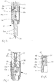
- the injection valve 2 for an internal combustion engine which is provided in particular as a diesel engine and which is not shown.
- the injection valve 2 is suitable for a conventional injection system of a diesel engine, so that a detailed explanation can be dispensed with in this regard. It essentially has a multi-part valve housing 47, 53 which can be assembled in a conventional manner, a valve body 15 which is guided longitudinally displaceably therein, a control valve 20 which actuates the latter and is designed as an electromagnetic valve 227, an inflow line 13 for the fuel under high pressure and an outflow line 10.
- the multi-part valve body 15 is surrounded in the lower part by a pressure chamber 14 supplied with fuel by the inflow line 13 and it closes or opens an injection opening 4 leading into a working cylinder of the diesel engine or its feed line, which extends into the nozzle tip 24 of the valve housing 47 projecting into the working cylinder is included.
- this valve body In the central region, this valve body is guided in a fitting bore in the valve housing 47 and at the upper end it projects into a control chamber 17a and is further pressed there in the closing direction by a compression spring 97.
- the control chamber 17a is connected via the valve 25 and the inflow line 13 with a high-pressure part containing the fuel on the one hand and via the line part 19 and the control valve 20 which can be closed with the Drain line 10 connected on the other hand.
- a radial connection 92 to the injection valve 2 is provided for the inflow line 13, which has a connecting ring 70 encompassing the valve housing 47 and a threaded nut 72 pressing the inflow line 13 against the housing.
- a damping space 43 is provided between the nozzle needle 15a controlling the injection opening 4 and the valve body part 15b above it of the two-part valve body 15, as is also illustrated in the enlarged partial longitudinal section according to FIG. 2.
- this damping space 43 is preceded or followed by an almost play-free guide fit 44, 45 formed between the nozzle needle 15a and the valve housing 47 and, on the other hand, between the valve body part 15b and the valve housing 47. Accordingly, there is a limited inflow or outflow into or out of this damping space 43 from or into the adjacent pressure chamber 14 or chamber 49. In addition to the considerable advantage already mentioned, this protects the nozzle tip 24 by means of the damping space 43
- Another advantage is that the majority of the injection valve 2 can be composed of conventional components and therefore does not become more complex to manufacture.
- valve body 15 If the valve body 15 is subsequently closed, there is only a direct impact of the relatively light nozzle needle 15a in the nozzle tip 24, meanwhile the valve body part 15b, which is also moved in the closing direction, is cushioned by the liquid cushion formed between it and the nozzle needle and thereby the desired permanent reduction of the maximum load of the lowest tip of the injection valve 2 has been reached.
- the safety can be increased, for example, when the control valve 20 is jammed and the injection opening 4 remains open, the damping chamber 43 is continuously supplied with fuel and consequently the nozzle needle 15a from the valve body part 15b to a closure of the injection opening 4 drifts away.
- This damping space 43 also preferably has a maximum volume that corresponds approximately to the cross-sectional area of the nozzle needle 15a and a gap height of a maximum of two millimeters.
- the control valve 20, designed as an electromagnetic valve 227, has a control valve body 38, which closes or opens the vertical line part 19 in the valve housing 47, which subsequently merges into a horizontal drain line 10, through a lower end valve seat 57.
- This control valve body 38 has a bore 60 'which starts from its valve seat 57 and communicates with the line part 19 and which is widened in the interior of the control valve body 38 for the purpose of generating a closing force acting in the closing direction thereof.
- this bore 60 ' is delimited at the top by a pin 60, which is arranged coaxially in the control valve body 38 and is longitudinally movably arranged at its upper end independently of the control valve body 38, in the present example on the lower end face of a pin arranged in the magnetic core 22, with sufficient hardness provided pin is supported.
- the lower end face of the magnetic core 22 lies directly on the film disk 61, which in turn is thereby fixed on a flat annular surface of the valve housing.
- recesses 66 are provided in the magnet armature 62 and its neighboring parts, through which the fuel surrounding the armature can flow around when the armature is moved.
- the damping effect of the reciprocating control valve body 38 can be set by a corresponding choice of the cross section of the recesses 66.
- a further valve 25 is arranged above this nozzle needle 15 in order to produce an increased closing speed of the valve body, said valve having an annular chamber 28 connected to the high-pressure part of the control medium via the inflow line 13 and an annular valve seat 27 closing it at the top on the front side, which when opening this additional connection between the high pressure part and the control chamber 17b generated.
- the valve 25 expediently has a valve body 26 which extends coaxially to the nozzle needle 15 and is guided laterally in a sealing manner in the valve housing 47. This cylindrical valve body 26 and the valve housing 47 together form the annular chamber 28 and the valve seat 27 that closes off this chamber 28.
- the valve body 26 projects with one end facing the nozzle needle 15 into the control chamber 17a and with the other end into one with the Drain line 10 via the additional chamber 17b communicating with the control valve 20, which is connected to the control chamber 17a via a throttle bore 23 which is continuous in the valve body 26 and adjoins the circumferential side of the valve seat 27.
- the latter is designed in such a way that the valve body 26 with its upper oblique ring edge lies in the closed state in a sealing manner against a corresponding ring surface in the housing bore and the annular chamber 28 surrounds the valve body 26 at least in its upper region.
- This conical valve seat 27 could also be cylindrical or a flat surface.
- the valve body 26 is provided with a transverse throttle bore 21 connecting the inflow line 13 to the control chamber 17b, by means of which the control medium is permanently connected from the high-pressure part into this control chamber.
- valve body 26 In the closed position, the valve body 26 is at a predetermined distance from the nozzle needle 15 located beneath it, and a compression spring 96 which presses it apart is provided between them, while in the open position the nozzle needle 15, which is released by releasing the control valve 20 and a pressure drop associated therewith Control chamber 17a is caused, this nozzle needle 15a strikes the lower end face 16 of the valve body 26.
- the transverse throttle bore 21 builds up pressure in the additional chamber 17b, as a result of which the valve body 26 moves against the nozzle needle 15a and thus causes the valve seat 27 to open automatically.
- an additional inflow of the high-pressure control medium flows into the additional chamber 17b and, as a result, the nozzle needle 15a is brought into the closed position by the valve body 26 at an increased speed.
- the valve body 26 is moved back up again due to the pressure build-up in the control chamber 17a and the spring force support of the spring 96, namely until its upper ring edge abuts the housing bore and the valve seat 27 is again in the closed position.
- the illustrated damping space 43 is not, as in the first exemplary embodiment, directly surrounded by the valve housing 47 but by an annular element 15d which is axially displaceable in the latter, the latter forming the lower end of the valve body part 15b.
- the nozzle needle 15a which in turn opens or closes the inlet opening 4, projects almost without play into this ring element 15d and, together with a spacer 15c arranged above it in the ring element 15, delimits the damping space 43.
- Length tolerances can be selected by a corresponding choice of the length of the spacer 15c compensate for the length formed by the valve body 15 together with the valve body 26 and the corresponding length formed by the housing parts 47, 53.
- the nozzle needle 15a has, at least in the lower region, a non-circular cross-section, as a result of which it forms a free space for the pressure chamber in the round bore of the valve housing. Otherwise, this injection valve 2 functions analogously to that according to FIG. 1 and therefore all details are no longer explained. It has the advantage according to FIG. 1 that it is provided with a smaller number of surfaces to be ground and there is no precise guiding fit in the housing 47, as a result of which it can be produced from a tougher material and in any case one high-frequency oscillating stroke of the nozzle needle 15a is generated.
- FIG. 4 shows a further variant of an injection valve 2 in the part relevant to the invention. It is constructed in a manner similar to that according to FIG. 3, but the ring element 15d is provided for this purpose independently of the upper valve body part 15b. The latter and the nozzle needle 15a are guided in the ring element 15d with a round design with almost no play therein. According to the invention, a damping space 43 is again provided between the nozzle needle 15a and the valve body part 15b.
- the ring element 15d surrounding this is designed as an internally sealing tube and, with a correspondingly thin wall, can also consist of plastic instead of a metallic material. It is placed over the two ends of the nozzle needle 15a and the valve body part 15b and forms a tight fit together with them.
- this injection valve is inexpensive to manufacture and the ring element 15d used therein can transmit tensile forces and has a somewhat articulated function. If this ring element 15d is ground on the inside and is not stuck on the nozzle needle 15a and on the valve body part 15b, then the compression spring 97 acting on the end face serves to position the same.
- the valve body 5 has a ring element 15d similar to that according to FIG. 4, which has a different inside diameter in the area connected to the nozzle needle 15a to the area connected to the valve body part 15b. It is supported on its upper end face on the compression spring 97.
- the guide cross section of the valve body part 15b in the ring element 15d is larger than that of the nozzle needle 15a. A complete opening stroke of the nozzle needle 15a is thus achieved with slight superimposed vibrations and upon closing the kinetic energy of the valve body part 15b is transmitted to the ring element 15d through the stop surface formed by the diameter reduction of the latter.
- damping space 43 could additionally be connected to the pressure chamber via a throttle bore connected in parallel with the guide fits.
- control medium flowing into the control chambers is normally fuel which is, as it were, injected into the storage chamber and subsequently through the injection openings into a fuel cylinder.
- a separate liquid could be used as the control medium, while the fuel would only be provided for the injection.
- damping chamber 43 could be connected to a leakage oil return line leading away from the injection valve and having a lower pressure than the pressure chamber.
- the pressure chamber 49 could have a low pressure corresponding to the drain line 10.
- the damping effect according to the invention is ensured if the passage cross section through the guide fitting 45 to the passage cross section formed by the guide fitting 44 is not more than ten times larger.
- the invention is sufficiently demonstrated with the exemplary embodiments explained above.
- the nozzle needle 15a could be made in two parts and the damping space would be arranged above this two-part nozzle needle.
Landscapes
- Engineering & Computer Science (AREA)
- Chemical & Material Sciences (AREA)
- Combustion & Propulsion (AREA)
- Mechanical Engineering (AREA)
- General Engineering & Computer Science (AREA)
- Physics & Mathematics (AREA)
- Fluid Mechanics (AREA)
- Fuel-Injection Apparatus (AREA)
Applications Claiming Priority (3)
| Application Number | Priority Date | Filing Date | Title |
|---|---|---|---|
| CH01358/94A CH689267A5 (de) | 1994-05-02 | 1994-05-02 | Einspritzventil fuer eine Kraftstoffeinspritzanlage einer Brennkraftmaschine, insbesondere eines Dieselmotors. |
| CH135894 | 1994-05-02 | ||
| CH1358/94 | 1994-05-02 |
Publications (3)
| Publication Number | Publication Date |
|---|---|
| EP0685645A2 true EP0685645A2 (fr) | 1995-12-06 |
| EP0685645A3 EP0685645A3 (fr) | 1997-03-26 |
| EP0685645B1 EP0685645B1 (fr) | 2001-06-06 |
Family
ID=4208593
Family Applications (1)
| Application Number | Title | Priority Date | Filing Date |
|---|---|---|---|
| EP95103560A Expired - Lifetime EP0685645B1 (fr) | 1994-05-02 | 1995-03-13 | Soupape d'injection pour un système d'injection de combustible d'un moteur à combustion interne, en particulier d'un moteur diesel |
Country Status (6)
| Country | Link |
|---|---|
| US (1) | US5692683A (fr) |
| EP (1) | EP0685645B1 (fr) |
| JP (1) | JP3710163B2 (fr) |
| AT (1) | ATE201920T1 (fr) |
| CH (1) | CH689267A5 (fr) |
| DE (1) | DE59509315D1 (fr) |
Cited By (2)
| Publication number | Priority date | Publication date | Assignee | Title |
|---|---|---|---|---|
| FR2871876A1 (fr) * | 2004-06-21 | 2005-12-23 | Valeo Climatisation Sa | Dispositif d'echange de chaleur a plusieurs rangees de tubes, en particulier pour vehicules automobiles |
| WO2012130452A1 (fr) * | 2011-03-31 | 2012-10-04 | Fuechslin Raphael | Soupape d'injection |
Families Citing this family (4)
| Publication number | Priority date | Publication date | Assignee | Title |
|---|---|---|---|---|
| DE19917190A1 (de) | 1999-04-16 | 2000-10-26 | Mtu Friedrichshafen Gmbh | Kraftstoffinjektor für eine Brennkraftmaschine |
| JP4066959B2 (ja) * | 2004-01-27 | 2008-03-26 | 株式会社デンソー | 燃料噴射装置 |
| US7900604B2 (en) * | 2005-06-16 | 2011-03-08 | Siemens Diesel Systems Technology | Dampening stop pin |
| JP6137030B2 (ja) * | 2014-04-10 | 2017-05-31 | 株式会社デンソー | 燃料噴射弁 |
Family Cites Families (9)
| Publication number | Priority date | Publication date | Assignee | Title |
|---|---|---|---|---|
| DE2710138A1 (de) * | 1977-03-09 | 1978-09-14 | Maschf Augsburg Nuernberg Ag | Mehrloch-einspritzduese |
| GB2096701A (en) * | 1981-04-11 | 1982-10-20 | Lucas Industries Ltd | I.C. engine fuel injection nozzles |
| DE3220398A1 (de) * | 1982-01-26 | 1983-07-28 | Robert Bosch Gmbh, 7000 Stuttgart | Kraftstoff-einspritzduese fuer brennkraftmaschinen |
| US4566635A (en) * | 1983-08-10 | 1986-01-28 | Robert Bosch Gmbh | Fuel injection nozzle for internal combustion engines |
| GB8809269D0 (en) * | 1988-04-20 | 1988-05-25 | Lucas Ind Plc | Fuel injection nozzle |
| EP0343147A3 (fr) * | 1988-05-16 | 1990-10-03 | Steyr-Daimler-Puch Aktiengesellschaft | Soupape d'injection pour moteurs à combustion interne à injection à compression d'air |
| DE3844373A1 (de) * | 1988-12-30 | 1990-07-05 | Mak Maschinenbau Krupp | Verfahren und vorrichtung zum einstellen eines definierten duesenoeffnungsdruckes eines einspritzventils |
| US5156132A (en) * | 1989-04-17 | 1992-10-20 | Nippondenso Co., Ltd. | Fuel injection device for diesel engines |
| DE4126698A1 (de) * | 1991-08-13 | 1992-10-15 | Daimler Benz Ag | Kraftstoffeinspritzduese fuer brennkraftmaschinen |
-
1994
- 1994-05-02 CH CH01358/94A patent/CH689267A5/de not_active IP Right Cessation
-
1995
- 1995-03-13 AT AT95103560T patent/ATE201920T1/de active
- 1995-03-13 DE DE59509315T patent/DE59509315D1/de not_active Expired - Lifetime
- 1995-03-13 EP EP95103560A patent/EP0685645B1/fr not_active Expired - Lifetime
- 1995-04-27 JP JP10423695A patent/JP3710163B2/ja not_active Expired - Lifetime
- 1995-05-01 US US08/432,110 patent/US5692683A/en not_active Expired - Lifetime
Cited By (3)
| Publication number | Priority date | Publication date | Assignee | Title |
|---|---|---|---|---|
| FR2871876A1 (fr) * | 2004-06-21 | 2005-12-23 | Valeo Climatisation Sa | Dispositif d'echange de chaleur a plusieurs rangees de tubes, en particulier pour vehicules automobiles |
| WO2006008389A1 (fr) * | 2004-06-21 | 2006-01-26 | Valeo Systemes Thermiques | Dispositif d'echange de chaleur a plusieurs rangees de tubes, en particulier pour vehicules automobiles |
| WO2012130452A1 (fr) * | 2011-03-31 | 2012-10-04 | Fuechslin Raphael | Soupape d'injection |
Also Published As
| Publication number | Publication date |
|---|---|
| EP0685645A3 (fr) | 1997-03-26 |
| CH689267A5 (de) | 1999-01-15 |
| JP3710163B2 (ja) | 2005-10-26 |
| EP0685645B1 (fr) | 2001-06-06 |
| US5692683A (en) | 1997-12-02 |
| JPH0842422A (ja) | 1996-02-13 |
| DE59509315D1 (de) | 2001-07-12 |
| ATE201920T1 (de) | 2001-06-15 |
Similar Documents
| Publication | Publication Date | Title |
|---|---|---|
| EP1636485B1 (fr) | Injecteur pour systemes d'injection de carburant de moteurs a combustion interne, en particulier de moteurs diesel a injection directe | |
| EP0675281B1 (fr) | Soupape d'injection pour moteur, particulierement pour moteur diesel | |
| DE2742466A1 (de) | Pumpe-duese fuer luftverdichtende einspritzbrennkraftmaschinen | |
| EP0686763A1 (fr) | Injecteur de combustible pour moteurs à combustion interne | |
| DE19946827C1 (de) | Ventil zum Steuern von Flüssigkeiten | |
| DE69918058T2 (de) | Hydraulisch betätigter brennstoffinjektor mit nadelventilsitzbetätiger | |
| EP1387937B1 (fr) | Soupape d'injection de carburant pour moteurs a combustion, comprenant une chambre d'amortissement reduisant les oscillations de pression | |
| DE3844489A1 (de) | Kraftstoffeinspritzvorrichtung | |
| EP1339966A1 (fr) | Injecteur comportant deux pointeaux d'injection pouvant etre commandes separement | |
| WO2001073287A1 (fr) | Soupape d'injection a etranglement de derivation | |
| DE19949528A1 (de) | Doppelschaltendes Steuerventil für einen Injektor eines Kraftstoffeinspritzsystems für Brennkraftmaschinen mit hydraulischer Verstärkung des Aktors | |
| EP0824190A2 (fr) | Soupape d'injection de combustible | |
| DE3115908A1 (de) | "brennstoffpumpe" | |
| DE2608937A1 (de) | Einspritzduese | |
| EP1853813B1 (fr) | Injecteur | |
| EP1774166A1 (fr) | Dispositif pour injecter du carburant dans la chambre de combustion d'un moteur a combustion interne | |
| EP0685645B1 (fr) | Soupape d'injection pour un système d'injection de combustible d'un moteur à combustion interne, en particulier d'un moteur diesel | |
| DE3247584A1 (de) | Kraftstoffeinspritzpumpe fuer brennkraftmaschinen | |
| EP1931874A1 (fr) | Dispositif pour injecter des carburants dans la chambre de combustion d'un moteur a combustion interne | |
| EP1276983B1 (fr) | Soupape servant a diriger des liquides | |
| EP1483499A1 (fr) | Systeme pour moduler en pression le comportement d'injection | |
| EP1908953B1 (fr) | Dispositif d'injection de carburant | |
| DE3214040A1 (de) | Kraftstoffeinspritzduese, insbesondere fuer einen schnellaufenden fahrzeug-dieselmotor | |
| EP1703119A1 (fr) | Buse d'injection de carburant | |
| DE19940289B4 (de) | Kraftstoffeinspritzventil |
Legal Events
| Date | Code | Title | Description |
|---|---|---|---|
| PUAI | Public reference made under article 153(3) epc to a published international application that has entered the european phase |
Free format text: ORIGINAL CODE: 0009012 |
|
| AK | Designated contracting states |
Kind code of ref document: A2 Designated state(s): AT DE FR GB IT SE |
|
| PUAL | Search report despatched |
Free format text: ORIGINAL CODE: 0009013 |
|
| AK | Designated contracting states |
Kind code of ref document: A3 Designated state(s): AT DE FR GB IT SE |
|
| 17P | Request for examination filed |
Effective date: 19970515 |
|
| 17Q | First examination report despatched |
Effective date: 19970627 |
|
| GRAG | Despatch of communication of intention to grant |
Free format text: ORIGINAL CODE: EPIDOS AGRA |
|
| GRAG | Despatch of communication of intention to grant |
Free format text: ORIGINAL CODE: EPIDOS AGRA |
|
| GRAG | Despatch of communication of intention to grant |
Free format text: ORIGINAL CODE: EPIDOS AGRA |
|
| GRAH | Despatch of communication of intention to grant a patent |
Free format text: ORIGINAL CODE: EPIDOS IGRA |
|
| GRAH | Despatch of communication of intention to grant a patent |
Free format text: ORIGINAL CODE: EPIDOS IGRA |
|
| GRAA | (expected) grant |
Free format text: ORIGINAL CODE: 0009210 |
|
| AK | Designated contracting states |
Kind code of ref document: B1 Designated state(s): AT DE FR GB IT SE |
|
| REF | Corresponds to: |
Ref document number: 201920 Country of ref document: AT Date of ref document: 20010615 Kind code of ref document: T |
|
| GBT | Gb: translation of ep patent filed (gb section 77(6)(a)/1977) |
Effective date: 20010607 |
|
| REF | Corresponds to: |
Ref document number: 59509315 Country of ref document: DE Date of ref document: 20010712 |
|
| ITF | It: translation for a ep patent filed | ||
| ET | Fr: translation filed | ||
| REG | Reference to a national code |
Ref country code: GB Ref legal event code: IF02 |
|
| PLBE | No opposition filed within time limit |
Free format text: ORIGINAL CODE: 0009261 |
|
| STAA | Information on the status of an ep patent application or granted ep patent |
Free format text: STATUS: NO OPPOSITION FILED WITHIN TIME LIMIT |
|
| 26N | No opposition filed | ||
| PGFP | Annual fee paid to national office [announced via postgrant information from national office to epo] |
Ref country code: SE Payment date: 20140311 Year of fee payment: 20 |
|
| PGFP | Annual fee paid to national office [announced via postgrant information from national office to epo] |
Ref country code: AT Payment date: 20140226 Year of fee payment: 20 Ref country code: IT Payment date: 20140318 Year of fee payment: 20 Ref country code: FR Payment date: 20140311 Year of fee payment: 20 |
|
| PGFP | Annual fee paid to national office [announced via postgrant information from national office to epo] |
Ref country code: GB Payment date: 20140312 Year of fee payment: 20 |
|
| PGFP | Annual fee paid to national office [announced via postgrant information from national office to epo] |
Ref country code: DE Payment date: 20140417 Year of fee payment: 20 |
|
| REG | Reference to a national code |
Ref country code: DE Ref legal event code: R071 Ref document number: 59509315 Country of ref document: DE |
|
| REG | Reference to a national code |
Ref country code: GB Ref legal event code: PE20 Expiry date: 20150312 |
|
| REG | Reference to a national code |
Ref country code: SE Ref legal event code: EUG |
|
| REG | Reference to a national code |
Ref country code: AT Ref legal event code: MK07 Ref document number: 201920 Country of ref document: AT Kind code of ref document: T Effective date: 20150313 |
|
| PG25 | Lapsed in a contracting state [announced via postgrant information from national office to epo] |
Ref country code: GB Free format text: LAPSE BECAUSE OF EXPIRATION OF PROTECTION Effective date: 20150312 |