EP0685748A1 - Senseur lumineux à suppression du bruit de fond, realisé au moyen du processus de quotient - Google Patents
Senseur lumineux à suppression du bruit de fond, realisé au moyen du processus de quotient Download PDFInfo
- Publication number
- EP0685748A1 EP0685748A1 EP95105444A EP95105444A EP0685748A1 EP 0685748 A1 EP0685748 A1 EP 0685748A1 EP 95105444 A EP95105444 A EP 95105444A EP 95105444 A EP95105444 A EP 95105444A EP 0685748 A1 EP0685748 A1 EP 0685748A1
- Authority
- EP
- European Patent Office
- Prior art keywords
- distance
- signal
- light
- predetermined distance
- threshold
- Prior art date
- Legal status (The legal status is an assumption and is not a legal conclusion. Google has not performed a legal analysis and makes no representation as to the accuracy of the status listed.)
- Granted
Links
Images

Classifications
-
- G—PHYSICS
- G01—MEASURING; TESTING
- G01S—RADIO DIRECTION-FINDING; RADIO NAVIGATION; DETERMINING DISTANCE OR VELOCITY BY USE OF RADIO WAVES; LOCATING OR PRESENCE-DETECTING BY USE OF THE REFLECTION OR RERADIATION OF RADIO WAVES; ANALOGOUS ARRANGEMENTS USING OTHER WAVES
- G01S17/00—Systems using the reflection or reradiation of electromagnetic waves other than radio waves, e.g. lidar systems
- G01S17/02—Systems using the reflection of electromagnetic waves other than radio waves
- G01S17/06—Systems determining position data of a target
- G01S17/46—Indirect determination of position data
- G01S17/48—Active triangulation systems, i.e. using the transmission and reflection of electromagnetic waves other than radio waves
-
- G—PHYSICS
- G01—MEASURING; TESTING
- G01S—RADIO DIRECTION-FINDING; RADIO NAVIGATION; DETERMINING DISTANCE OR VELOCITY BY USE OF RADIO WAVES; LOCATING OR PRESENCE-DETECTING BY USE OF THE REFLECTION OR RERADIATION OF RADIO WAVES; ANALOGOUS ARRANGEMENTS USING OTHER WAVES
- G01S17/00—Systems using the reflection or reradiation of electromagnetic waves other than radio waves, e.g. lidar systems
- G01S17/02—Systems using the reflection of electromagnetic waves other than radio waves
- G01S17/04—Systems determining the presence of a target
-
- G—PHYSICS
- G01—MEASURING; TESTING
- G01S—RADIO DIRECTION-FINDING; RADIO NAVIGATION; DETERMINING DISTANCE OR VELOCITY BY USE OF RADIO WAVES; LOCATING OR PRESENCE-DETECTING BY USE OF THE REFLECTION OR RERADIATION OF RADIO WAVES; ANALOGOUS ARRANGEMENTS USING OTHER WAVES
- G01S7/00—Details of systems according to groups G01S13/00, G01S15/00, G01S17/00
- G01S7/48—Details of systems according to groups G01S13/00, G01S15/00, G01S17/00 of systems according to group G01S17/00
- G01S7/491—Details of non-pulse systems
- G01S7/4912—Receivers
-
- G—PHYSICS
- G01—MEASURING; TESTING
- G01S—RADIO DIRECTION-FINDING; RADIO NAVIGATION; DETERMINING DISTANCE OR VELOCITY BY USE OF RADIO WAVES; LOCATING OR PRESENCE-DETECTING BY USE OF THE REFLECTION OR RERADIATION OF RADIO WAVES; ANALOGOUS ARRANGEMENTS USING OTHER WAVES
- G01S7/00—Details of systems according to groups G01S13/00, G01S15/00, G01S17/00
- G01S7/48—Details of systems according to groups G01S13/00, G01S15/00, G01S17/00 of systems according to group G01S17/00
- G01S7/491—Details of non-pulse systems
- G01S7/493—Extracting wanted echo signals
Definitions
- the invention relates to a photoelectric light scanner which has a light transmitter in a housing, which emits a bundled transmission beam and contains a photoelectric converter arrangement which receives a portion of the transmission beam reflected from an object.
- Such light scanners are used in a predetermined distance range z. B. to recognize guided light reflecting objects.
- Light scanners with background suppression are known today, in which the distance information is obtained by essentially assigning the object distance to one of two possible states, i. H. the object is located between the light sensor and the limit distance or outside the limit distance.
- Such light scanners work according to the known triangulation principle (DE-PS 35 13 671).
- the receiving lens is arranged next to the transmitting lens, so that a finite angle is always established between the transmitting beam and the effective receiving beam reflected on the object. This angle changes depending on the distance between the object and the light sensor.
- a photoelectric transducer arrangement arranged in the button consisting of two or more photoelectric receivers, is able to differentiate whether the origin of the light reflection on the object, outside or within a predetermined one Range.
- the reflected light is focused on the "near element"; if the object is outside the predetermined distance, the reflected radiation is focused on the adjacent "far element”; If the object is at the limit point of the predetermined distance, the reflected amount of light is imaged almost uniformly on the dividing line of the two elements. Corresponding photocurrents are generated depending on the respective irradiance on the two elements.
- the two photoelectric signals are fed to a differential amplifier (G 91 05 710.8).
- the differential amplifier is connected to an evaluation circuit which emits a presence signal only in the case of a signal with the sign that occurs when an object is present at a smaller distance than the limit distance.
- the evaluation circuit contains a switching threshold, such that a presence signal is only given when the signal, which has the correct sign, is clearly different from 0 at the output of the differential amplifier is.
- the invention is based on the object of eliminating the dependence in the limit distance on the reflectance of the object or reducing it as far as possible. If, for example, a light scanner of this type is used to control the fill level, the predetermined limit distance, ie the fill mark for all materials, should be at exactly the same location and should not depend on the degree of remissios of the material to be filled.
- the button should therefore z. B. dark coffee just like z. B. Report white sugar at the same border point.
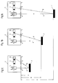
- the receiving front lens (3) and the transmitting front lens (4) are arranged side by side in the front wall 1 of a cuboid flat housing (2). Near the focal point of the transmission front lens (4) there is a luminescence diode (5) as the light source, so that a bundled transmission light beam (6) is emitted from the transmission front lens (4) perpendicular to the front wall (1).
- a light-reflecting object (7) is arranged in front of the front wall (1) in a scanning range (B), which diffusely reflects back the emerging light of the transmission beam (6).
- a narrow section of this diffuse scattering cone, which forms around the central beam (8), is from the receiving front lens (3) recorded and focused in the plane of the two photo converters (9, 10) behind it.
- the focused receiving beam (8) falls exactly on the dividing line of the two photo converters (9, 10). Both photoconverters are thereby partially irradiated. If, however, the object (7) is in a larger scanning distance (A) according to FIG. 1a, the receiving beam (8) falls exclusively on the photo converter (9); if, on the other hand, the object (7) is in a shorter scanning distance (C) according to FIG. 1c, the light bundle around the beam (8) is focused on the photo converter (10).
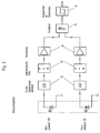
- Both photo converters (9, 10) are connected to an evaluation circuit which contains the quotient formation according to the invention.
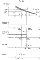
- FIG. 3a shows the difference signal known from the prior art over the scanning range in the range of (B).
- (20) means the signal curve for a white object and (21) for a black object. Due to the high degree of reflectance with white objects, this signal is practically noiseless, which is expressed by a sharp line (20) in FIG. 3a).
- the signal from objects with a low degree of reflectance e.g. black cloth
- a clear noise which is expressed by a hatched band (21).
- the two signals are now cut by the "threshold on” (22) and the “threshold off” (23). Now move in black object coming from the scanning distance (A) towards the light sensor, the threshold (22) is safely exceeded at the location (24).
- the threshold (22) is exceeded at the location (25).
- the situation is similar if the probe material is moved away from the light scanner, coming from the scanning distance (C). With black material, the threshold (23) at the location (26) is undershot, with white material, however, at the location (27). Disruptive to this method according to the known prior art is the large difference in the material-dependent switch-off location ( ⁇ A) or switch-on location ( ⁇ B).
- (28) means the signal curve for a white object and (29) for a black object.
- the signal is practically noiseless due to the high degree of reflectance in white objects, which is shown by a sharp line (28).
- a clear noise is superimposed on the signal from black objects, which is expressed by a hatched band (29).
- the signal curve (the quotient value as a function of the scanning distance) has the same curve regardless of the degree of reflection of the scanning material.
- the switching process is triggered. If a black object now moves from the scanning range (A) towards the light scanner, the threshold (22) is safely exceeded at location (30). If, on the other hand, it is a white touch material, the threshold (22) at the location (31) is exceeded. The situation is similar if the probe material is moved away from the light scanner, coming from the scanning distance (C). With black material, the threshold (23) at the location (32) is undershot, with white material on the other hand (33). According to this method, the difference between the material-dependent switch-off locations ( ⁇ A ') and switch-on locations ( ⁇ B') is significantly smaller than according to the differential method.
Landscapes
- Physics & Mathematics (AREA)
- Electromagnetism (AREA)
- Engineering & Computer Science (AREA)
- Computer Networks & Wireless Communication (AREA)
- General Physics & Mathematics (AREA)
- Radar, Positioning & Navigation (AREA)
- Remote Sensing (AREA)
- Geophysics And Detection Of Objects (AREA)
- Measurement Of Optical Distance (AREA)
- Switches Operated By Changes In Physical Conditions (AREA)
- Electronic Switches (AREA)
- Length Measuring Devices By Optical Means (AREA)
Applications Claiming Priority (2)
| Application Number | Priority Date | Filing Date | Title |
|---|---|---|---|
| DE4419032A DE4419032A1 (de) | 1994-05-31 | 1994-05-31 | Lichttaster mit Hintergrundausblendung, realisiert nach dem Quotientenverfahren |
| DE4419032 | 1994-05-31 |
Publications (2)
| Publication Number | Publication Date |
|---|---|
| EP0685748A1 true EP0685748A1 (fr) | 1995-12-06 |
| EP0685748B1 EP0685748B1 (fr) | 1998-07-22 |
Family
ID=6519456
Family Applications (1)
| Application Number | Title | Priority Date | Filing Date |
|---|---|---|---|
| EP95105444A Expired - Lifetime EP0685748B1 (fr) | 1994-05-31 | 1995-04-11 | Senseur lumineux à suppression du bruit de fond, realisé au moyen du processus de quotient |
Country Status (3)
| Country | Link |
|---|---|
| EP (1) | EP0685748B1 (fr) |
| DE (2) | DE4419032A1 (fr) |
| DK (1) | DK0685748T3 (fr) |
Cited By (5)
| Publication number | Priority date | Publication date | Assignee | Title |
|---|---|---|---|---|
| EP1209487A1 (fr) * | 2000-11-24 | 2002-05-29 | DATASENSOR S.p.A. | Procédé et dispositif pour la détection d'un objet, à suppression du bruit de fond |
| US6400460B1 (en) | 2000-04-10 | 2002-06-04 | Honeywell International Inc. | Multifunction optical sensor with variable detection threshold and noise suppression |
| EP2434311A1 (fr) * | 2010-09-27 | 2012-03-28 | Sick Ag | Procédé de surveillance optique d'un domaine de surveillance et senseur lumineux à réflexion |
| EP2963444A1 (fr) * | 2014-07-03 | 2016-01-06 | Sick Ag | Capteur et procédé de détection à un endroit précis d'un objet transporté dans une direction de transport, par rapport à un capteur |
| EP3112899A1 (fr) * | 2015-06-29 | 2017-01-04 | Azbil Corporation | Capteur photoelectrique |
Families Citing this family (4)
| Publication number | Priority date | Publication date | Assignee | Title |
|---|---|---|---|---|
| DE19619308A1 (de) * | 1996-05-13 | 1997-11-20 | Sick Ag | Kombinations-Lichttaster |
| DE102013208664C5 (de) | 2012-12-12 | 2019-07-18 | Ifm Electronic Gmbh | Verfahren zum Betreiben eines Triangulations-Lichttasters |
| DE102016101269A1 (de) * | 2016-01-25 | 2017-07-27 | Balluff Gmbh | Optoelektronischer Multifunktionssensor und Verfahren zu seinem Betrieb |
| DE102024128982A1 (de) * | 2024-10-08 | 2026-04-09 | Sick Ag | Reflexions-Lichttaster |
Citations (4)
| Publication number | Priority date | Publication date | Assignee | Title |
|---|---|---|---|---|
| DE3407210A1 (de) * | 1984-02-28 | 1985-09-12 | Matsushita Electric Works, Ltd., Kadoma, Osaka | Photoelektrischer schalter |
| EP0198253A2 (fr) * | 1985-04-16 | 1986-10-22 | Erwin Sick GmbH Optik-Elektronik | Senseur lumineux |
| WO1988005900A1 (fr) * | 1987-02-05 | 1988-08-11 | Santa Barbara Research Center | Detecteurs multiples avec suppression du brouillard et meilleure mise en contraste des contours |
| DE9105710U1 (de) * | 1991-05-08 | 1991-10-10 | Leuze electronic GmbH + Co, 7311 Owen | Lichtelektrische Einrichtung |
Family Cites Families (7)
| Publication number | Priority date | Publication date | Assignee | Title |
|---|---|---|---|---|
| DE3627972A1 (de) * | 1986-08-18 | 1988-02-25 | Ifm Int Fluggeraete Motoren | Photoelektrischer taster |
| DE3729334A1 (de) * | 1987-09-02 | 1989-03-16 | Sick Optik Elektronik Erwin | Lichttaster |
| DE4040225C2 (de) * | 1990-12-15 | 1994-01-05 | Leuze Electronic Gmbh & Co | Reflexions-Lichttaster |
| DE4115013C1 (en) * | 1991-05-08 | 1992-05-27 | Leuze Electronic Gmbh + Co, 7311 Owen, De | Photoelectric unit illuminating object to ascertain quality to its material - has deflecting mirror linearly slidable parallel to direction of optical axis of receiving front lens |
| DE4119797C2 (de) * | 1991-06-15 | 1994-02-24 | Leuze Electronic Gmbh & Co | Einen Sender, einen Empfänger und eine Schaltungsanordnung zur Signalauswertung aufweisende Überwachungseinrichtung |
| JPH074317B2 (ja) * | 1991-07-23 | 1995-01-25 | タイガー魔法瓶株式会社 | 炊飯器 |
| DE4125479C3 (de) * | 1991-08-01 | 2002-01-10 | Leuze Electronic Gmbh & Co | Reflexionslichttaster |
-
1994
- 1994-05-31 DE DE4419032A patent/DE4419032A1/de not_active Ceased
-
1995
- 1995-04-11 DE DE59502869T patent/DE59502869D1/de not_active Expired - Fee Related
- 1995-04-11 EP EP95105444A patent/EP0685748B1/fr not_active Expired - Lifetime
- 1995-04-11 DK DK95105444T patent/DK0685748T3/da active
Patent Citations (4)
| Publication number | Priority date | Publication date | Assignee | Title |
|---|---|---|---|---|
| DE3407210A1 (de) * | 1984-02-28 | 1985-09-12 | Matsushita Electric Works, Ltd., Kadoma, Osaka | Photoelektrischer schalter |
| EP0198253A2 (fr) * | 1985-04-16 | 1986-10-22 | Erwin Sick GmbH Optik-Elektronik | Senseur lumineux |
| WO1988005900A1 (fr) * | 1987-02-05 | 1988-08-11 | Santa Barbara Research Center | Detecteurs multiples avec suppression du brouillard et meilleure mise en contraste des contours |
| DE9105710U1 (de) * | 1991-05-08 | 1991-10-10 | Leuze electronic GmbH + Co, 7311 Owen | Lichtelektrische Einrichtung |
Cited By (10)
| Publication number | Priority date | Publication date | Assignee | Title |
|---|---|---|---|---|
| US6400460B1 (en) | 2000-04-10 | 2002-06-04 | Honeywell International Inc. | Multifunction optical sensor with variable detection threshold and noise suppression |
| WO2001077708A3 (fr) * | 2000-04-10 | 2002-07-18 | Honeywell Int Inc | Detecteur optique multifonctions a detection variable correspndante et suppression de bruit |
| EP1209487A1 (fr) * | 2000-11-24 | 2002-05-29 | DATASENSOR S.p.A. | Procédé et dispositif pour la détection d'un objet, à suppression du bruit de fond |
| EP2434311A1 (fr) * | 2010-09-27 | 2012-03-28 | Sick Ag | Procédé de surveillance optique d'un domaine de surveillance et senseur lumineux à réflexion |
| US8575582B2 (en) | 2010-09-27 | 2013-11-05 | Sick Ag | Method for the optical monitoring of a monitored zone and light sensor |
| EP2963444A1 (fr) * | 2014-07-03 | 2016-01-06 | Sick Ag | Capteur et procédé de détection à un endroit précis d'un objet transporté dans une direction de transport, par rapport à un capteur |
| EP3112899A1 (fr) * | 2015-06-29 | 2017-01-04 | Azbil Corporation | Capteur photoelectrique |
| CN106289513A (zh) * | 2015-06-29 | 2017-01-04 | 阿自倍尔株式会社 | 光电传感器 |
| CN106289513B (zh) * | 2015-06-29 | 2018-08-03 | 阿自倍尔株式会社 | 光电传感器 |
| US10061026B2 (en) | 2015-06-29 | 2018-08-28 | Azbil Corporation | Photoelectric sensor with disturbance detection |
Also Published As
| Publication number | Publication date |
|---|---|
| DK0685748T3 (da) | 1998-11-02 |
| EP0685748B1 (fr) | 1998-07-22 |
| DE4419032A1 (de) | 1996-01-25 |
| DE59502869D1 (de) | 1998-08-27 |
Similar Documents
| Publication | Publication Date | Title |
|---|---|---|
| EP1405037B1 (fr) | Dispositif de mesure optique de distance sur une plage de mesure etendue | |
| EP2002208B1 (fr) | Dispositif de mesure optique de distances et son procédé de fonctionnement | |
| EP2002281B1 (fr) | Dispositif de mesure optique de distances | |
| EP2238469B1 (fr) | Dispositif de détermination d'une distance à un objet | |
| DE10336458A1 (de) | System zur Abstandsmessung mittels Lichtquellen | |
| EP1816488B1 (fr) | Dispositif optoélectronique et son procédé de fonctionnement | |
| DE202009015321U1 (de) | Laser Entfernungs-Messvorrichtung | |
| EP2210124B1 (fr) | Dispositif de mesure optique d'une distance | |
| EP4310443B1 (fr) | Palpeur optique de triangulation | |
| EP3654056A1 (fr) | Capteur et procédé de détection d'objets | |
| DE19964539B4 (de) | Optoelektronische Vorrichtung zum Erfassen von Objekten | |
| EP0685748B1 (fr) | Senseur lumineux à suppression du bruit de fond, realisé au moyen du processus de quotient | |
| DE102015105263A1 (de) | Optoelektronischer Sensor und Verfahren zur Erfassung von Objekten in einem Überwachungsbereich | |
| DE4004530C2 (de) | Optische Abstandsmessung | |
| EP2040097B1 (fr) | Capteur optoélectronique | |
| DE10340420A1 (de) | Optoelektronische Vorrichtung | |
| AT412029B (de) | Verfahren zur aufnahme eines objektraumes | |
| DE102016219518B4 (de) | Lichtlaufzeitkamerasystem | |
| DE19619308A1 (de) | Kombinations-Lichttaster | |
| DE102016219516B4 (de) | Lichtlaufzeitkamerasystem | |
| DE19511990C2 (de) | Messvorrichtung zum Messen von Transversalgeschwindigkeit und Länge eines Messobjekts | |
| DE102020123541A1 (de) | Entfernungsmesssystem | |
| EP4249949B1 (fr) | Détection et détermination de la distance d'un objet | |
| EP1134595A2 (fr) | Méthode pour déterminer les distances d'objets employant un capteur à triangulation et capteur à triangulation pour réaliser la méthode | |
| EP2963444B1 (fr) | Capteur et procédé de détection à un endroit précis d'un objet transporté dans une direction de transport, par rapport à un capteur |
Legal Events
| Date | Code | Title | Description |
|---|---|---|---|
| PUAI | Public reference made under article 153(3) epc to a published international application that has entered the european phase |
Free format text: ORIGINAL CODE: 0009012 |
|
| AK | Designated contracting states |
Kind code of ref document: A1 Designated state(s): CH DE DK FR LI |
|
| 17P | Request for examination filed |
Effective date: 19960117 |
|
| 17Q | First examination report despatched |
Effective date: 19961119 |
|
| RAP1 | Party data changed (applicant data changed or rights of an application transferred) |
Owner name: SICK AG |
|
| GRAG | Despatch of communication of intention to grant |
Free format text: ORIGINAL CODE: EPIDOS AGRA |
|
| GRAG | Despatch of communication of intention to grant |
Free format text: ORIGINAL CODE: EPIDOS AGRA |
|
| GRAH | Despatch of communication of intention to grant a patent |
Free format text: ORIGINAL CODE: EPIDOS IGRA |
|
| GRAH | Despatch of communication of intention to grant a patent |
Free format text: ORIGINAL CODE: EPIDOS IGRA |
|
| GRAA | (expected) grant |
Free format text: ORIGINAL CODE: 0009210 |
|
| AK | Designated contracting states |
Kind code of ref document: B1 Designated state(s): CH DE DK FR LI |
|
| REG | Reference to a national code |
Ref country code: CH Ref legal event code: EP |
|
| REF | Corresponds to: |
Ref document number: 59502869 Country of ref document: DE Date of ref document: 19980827 |
|
| ET | Fr: translation filed | ||
| REG | Reference to a national code |
Ref country code: DK Ref legal event code: T3 |
|
| PG25 | Lapsed in a contracting state [announced via postgrant information from national office to epo] |
Ref country code: DK Free format text: LAPSE BECAUSE OF NON-PAYMENT OF DUE FEES Effective date: 19990411 |
|
| PG25 | Lapsed in a contracting state [announced via postgrant information from national office to epo] |
Ref country code: LI Free format text: LAPSE BECAUSE OF NON-PAYMENT OF DUE FEES Effective date: 19990430 Ref country code: CH Free format text: LAPSE BECAUSE OF NON-PAYMENT OF DUE FEES Effective date: 19990430 |
|
| PLBE | No opposition filed within time limit |
Free format text: ORIGINAL CODE: 0009261 |
|
| STAA | Information on the status of an ep patent application or granted ep patent |
Free format text: STATUS: NO OPPOSITION FILED WITHIN TIME LIMIT |
|
| 26N | No opposition filed | ||
| REG | Reference to a national code |
Ref country code: CH Ref legal event code: PL |
|
| PG25 | Lapsed in a contracting state [announced via postgrant information from national office to epo] |
Ref country code: FR Free format text: LAPSE BECAUSE OF NON-PAYMENT OF DUE FEES Effective date: 19991231 |
|
| REG | Reference to a national code |
Ref country code: FR Ref legal event code: ST |
|
| REG | Reference to a national code |
Ref country code: DK Ref legal event code: EBP |
|
| PGFP | Annual fee paid to national office [announced via postgrant information from national office to epo] |
Ref country code: DE Payment date: 20010525 Year of fee payment: 7 |
|
| PG25 | Lapsed in a contracting state [announced via postgrant information from national office to epo] |
Ref country code: DE Free format text: LAPSE BECAUSE OF NON-PAYMENT OF DUE FEES Effective date: 20021101 |