EP3112899A1 - Capteur photoelectrique - Google Patents
Capteur photoelectrique Download PDFInfo
- Publication number
- EP3112899A1 EP3112899A1 EP16176608.4A EP16176608A EP3112899A1 EP 3112899 A1 EP3112899 A1 EP 3112899A1 EP 16176608 A EP16176608 A EP 16176608A EP 3112899 A1 EP3112899 A1 EP 3112899A1
- Authority
- EP
- European Patent Office
- Prior art keywords
- light
- disturbance
- threshold
- unit
- photoelectric sensor
- Prior art date
- Legal status (The legal status is an assumption and is not a legal conclusion. Google has not performed a legal analysis and makes no representation as to the accuracy of the status listed.)
- Granted
Links
Images


Classifications
-
- G—PHYSICS
- G01—MEASURING; TESTING
- G01J—MEASUREMENT OF INTENSITY, VELOCITY, SPECTRAL CONTENT, POLARISATION, PHASE OR PULSE CHARACTERISTICS OF INFRARED, VISIBLE OR ULTRAVIOLET LIGHT; COLORIMETRY; RADIATION PYROMETRY
- G01J1/00—Photometry, e.g. photographic exposure meter
- G01J1/42—Photometry, e.g. photographic exposure meter using electric radiation detectors
- G01J1/44—Electric circuits
-
- G—PHYSICS
- G01—MEASURING; TESTING
- G01S—RADIO DIRECTION-FINDING; RADIO NAVIGATION; DETERMINING DISTANCE OR VELOCITY BY USE OF RADIO WAVES; LOCATING OR PRESENCE-DETECTING BY USE OF THE REFLECTION OR RERADIATION OF RADIO WAVES; ANALOGOUS ARRANGEMENTS USING OTHER WAVES
- G01S7/00—Details of systems according to groups G01S13/00, G01S15/00, G01S17/00
- G01S7/48—Details of systems according to groups G01S13/00, G01S15/00, G01S17/00 of systems according to group G01S17/00
- G01S7/497—Means for monitoring or calibrating
-
- G—PHYSICS
- G01—MEASURING; TESTING
- G01J—MEASUREMENT OF INTENSITY, VELOCITY, SPECTRAL CONTENT, POLARISATION, PHASE OR PULSE CHARACTERISTICS OF INFRARED, VISIBLE OR ULTRAVIOLET LIGHT; COLORIMETRY; RADIATION PYROMETRY
- G01J1/00—Photometry, e.g. photographic exposure meter
- G01J1/42—Photometry, e.g. photographic exposure meter using electric radiation detectors
- G01J1/4204—Photometry, e.g. photographic exposure meter using electric radiation detectors with determination of ambient light
-
- G—PHYSICS
- G01—MEASURING; TESTING
- G01S—RADIO DIRECTION-FINDING; RADIO NAVIGATION; DETERMINING DISTANCE OR VELOCITY BY USE OF RADIO WAVES; LOCATING OR PRESENCE-DETECTING BY USE OF THE REFLECTION OR RERADIATION OF RADIO WAVES; ANALOGOUS ARRANGEMENTS USING OTHER WAVES
- G01S17/00—Systems using the reflection or reradiation of electromagnetic waves other than radio waves, e.g. lidar systems
- G01S17/02—Systems using the reflection of electromagnetic waves other than radio waves
- G01S17/04—Systems determining the presence of a target
Definitions
- This invention relates to photoelectric sensors capable of avoiding erroneous operation caused by mutual interference.
- AC alternating-current
- LED light-emitting-diode
- a photoelectric sensor disclosed in Japanese Examined Patent Application Publication No. 62-7733 delays transmission of light by a predetermined period if a disturbance is detected.
- a photoelectric sensor disclosed in Japanese Unexamined Patent Application Publication No. 63-263917 transmits light while changing the light transmission cycle.
- a photoelectric sensor disclosed in Japanese Unexamined Patent Application Publication No. 2003-23347 detects a disturbance having an AC waveform by providing positive and negative thresholds in addition to a threshold used to determine the presence or absence of a target object. If a disturbance having an AC waveform is detected, the photoelectric sensor receives light at a zero-cross timing of the AC waveform. If no disturbance is detected for a predetermined period, the mode is switched into another mode. If a disturbance is detected in the other mode, transmission of light is delayed by a predetermined period.
- the method disclosed in Japanese Examined Patent Application Publication No. 62-7733 is less effective against mutual interference. Specifically, since strong disturbance light is input when mutual interference of photoelectric sensors occurs, a received light signal does not have a pulse waveform but rather has a fluctuating waveform in which the signal fluctuates a plurality of times. For this reason, even if light is transmitted after a predetermined period as in the method disclosed in Japanese Examined Patent Application Publication No. 62-7733 , a light signal supposed to be received may be lost due to saturation caused by the fluctuating waveform. In addition, the method disclosed in Japanese Examined Patent Application Publication No. 62-7733 is unable to avoid the influence of AC disturbance light.
- the method disclosed in Japanese Unexamined Patent Application Publication No. 63-263917 is less effective against AC disturbance light. Specifically, light is transmitted while changing the light transmission cycle in the method disclosed in Japanese Unexamined Patent Application Publication No. 63-263917 . Coincidence of reception timings of AC disturbance light and light of interest is inevitable, which may lead to erroneous operation.
- Japanese Unexamined Patent Application Publication No. 2003-23347 is less effective against mutual interference. Specifically, as described above, since strong disturbance light is input when mutual interference of photoelectric sensors occurs, a received light signal does not have a pulse waveform but rather has a fluctuating waveform. For this reason, even if light is transmitted after a predetermined period as in the method disclosed in Japanese Unexamined Patent Application Publication No. 2003-23347 , the light signal supposed to be received may be lost due to superimposition of the fluctuating waveform.
- the method disclosed in Japanese Unexamined Patent Application Publication No. 2003-23347 requires a comparator having a positive threshold and a comparator having a negative threshold in addition to a comparator having a threshold used to determine the presence or absence of a target object, increasing the scale of the circuit.
- the photoelectric sensor operates while switching between an AC disturbance light handling mode and a mutual interference handling mode, processing is complicated.
- the method disclosed in Japanese Unexamined Patent Application Publication No. 2003-23347 is to control the light transmission timing so that the light reception timing matches the zero-cross timing of the AC waveform of the disturbance.
- the noise frequency that can be coped with is limited.
- This invention has been made to overcome the issues described above, and it is an object of this invention to provide photoelectric sensors capable of avoiding erroneous operation caused by mutual interference more reliably than a configuration of the related art.
- a photoelectric sensor includes a light transmitter that transmits light and a light receiver that receives reflected light of the light transmitted by the light transmitter and detects presence or absence of a target object by comparing a light reception result obtained by the light receiver with a first threshold relative to a no-signal state.
- the photoelectric sensor further includes a disturbance detection unit that detects a disturbance by comparing the light reception result obtained by the light receiver with the first threshold and with a second threshold for a predetermined period in a state where no light is transmitted by the light transmitter, the second threshold taking a value of a sign opposite to that of the first threshold relative to the no-signal state; a waiting unit that waits, upon detection of a disturbance by the disturbance detection unit, for the light reception result obtained by the light receiver to become within a range from the first threshold to the second threshold; a disturbance type determination unit that causes the disturbance detection unit to perform detection of a disturbance again after the waiting unit has finished waiting; and a light transmission instruction unit that instructs the light transmitter to transmit light when no disturbance is detected by the disturbance detection unit for a predetermined period.
- a disturbance detection unit that detects a disturbance by comparing the light reception result obtained by the light receiver with the first threshold and with a second threshold for a predetermined period in a state where no light is transmitted by the light transmitter, the second threshold taking a value
- the photoelectric sensor since the photoelectric sensor is configured as described above, the photoelectric sensor is capable of avoiding erroneous operation caused by mutual interference more reliably than a configuration of the related art.
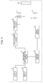
- Fig. 1 is a diagram illustrating an example of a configuration of a photoelectric sensor according to an embodiment of this invention.
- the photoelectric sensor includes a light transmitter that transmits light and a light receiver that receives reflected light of the light transmitted by the light transmitter.
- the photoelectric sensor detects the presence or absence of a target object 50 by comparing a light reception result obtained by the light receiver with a determination threshold.
- the determination threshold is a threshold (first threshold) that takes a positive value relative to a no-signal state.
- a distance-settable photoelectric sensor that detects the presence or absence of the target object 50 located at a distance smaller than the set distance with a two-element segmented photodiode whose light-receiving surface, which serves as a light-receiving element (one-dimensional position sensitive element) 5, is segmented to a near-side (N-side) light-receiving surface and a far-side (F-side) light-receiving surface.
- the photoelectric sensor includes a drive circuit 1, a light-transmitting element 2, a light-transmitting optical system 3, a light-receiving optical system 4, the light-receiving element 5, an arithmetic circuit 6, an amplification circuit 7, a comparison/determination circuit 8, an output circuit 9, a display circuit 10, and a control circuit 11.
- the drive circuit 1, the light-transmitting element 2, and the light-transmitting optical system 3 constitute the light transmitter, whereas the light-receiving optical system 4, the light-receiving element 5, the arithmetic circuit 6, and the amplification circuit 7 constitute the light receiver.
- the drive circuit 1 generates a current supplied to the light-transmitting element 2.
- the light-transmitting element 2 is driven by the current generated by the drive circuit 1 and emits light.
- an LED is used as this light-transmitting element 2.
- the light-transmitting optical system 3 condenses the light emitted by the light-transmitting element 2.
- the light condensed by this light-transmitting optical system 3 is transmitted to a target region. If the target object 50 is present in the target region, the light is reflected by this target object 50.
- the light-receiving optical system 4 condenses the light reflected by the target object 50 located in the target region.
- the light-receiving element 5 is a two-element segmented photodiode whose light-receiving surface is segmented into the N-side light-receiving surface and the F-side light-receiving surface and converts the light condensed by the light-receiving optical system 4 into electric signals (currents).
- This light-receiving element 5 is capable of detecting an amount of light received on the N-side light-receiving surface (first received light signal) and an amount of light received on the F-side light-receiving surface (second received light signal).
- the arithmetic circuit 6 converts the amount of light (current) received on the N-side light-receiving surface and the amount of light (current) received on the F-side light-receiving surface, which are detected by the light-receiving element 5, into voltages and determines a difference between the voltages.
- the amplification circuit 7 amplifies the voltage obtained by the processing performed by the arithmetic circuit 6 at a predetermined gain.
- the amplified voltage (differential signal) obtained by this amplification circuit 7 corresponds to a light reception result (distance signal generated from the first and second received light signals).
- the comparison/determination circuit 8 compares the amplified voltage obtained by the amplification circuit 7 with the determination threshold (positive threshold) to detect the presence or absence of the target object 50 in the target region. At that time, the comparison/determination circuit 8 determines that no object is in the target region if the amplified voltage obtained by the amplification circuit 7 is lower than the determination threshold and determines that an object is in the target region if the amplified voltage obtained by the amplification circuit 7 is higher than or equal to the determination threshold. For example, an up-down counter is used as this comparison/determination circuit 8.
- the output circuit 9 outputs information indicating a determination result obtained by the comparison/determination circuit 8. At that time, the output circuit 9 causes an output transistor to operate based on the information indicating the determination result.
- the display circuit 10 displays the information indicating the determination result obtained by the comparison/determination circuit 8 using an indicator lamp or the like.
- the control circuit 11 controls operations of the individual components of the photoelectric sensor.
- the control circuit 11 also has a function for controlling the light transmission timing for the light transmitter. As illustrated in Fig. 2 , this control circuit 11 includes an idle state control unit 111, a counter initialization unit 112, a disturbance detection unit 113, a counter unit 114, a waiting control unit 115, a disturbance type determination unit 116, and a light transmission instruction unit 117.
- the control circuit 11 is implemented by software-based program processing using a CPU.
- the idle state control unit 111 causes the photoelectric sensor to idle for a predetermined period upon the start of the photoelectric sensor or after every light transmission/reception process performed by the photoelectric sensor.
- the counter initialization unit 112 initializes and resets a count value of the counter unit 114 upon the start of the photoelectric sensor and after every light transmission/reception process performed by the photoelectric sensor, respectively.
- the disturbance detection unit 113 detects a disturbance by comparing the received light signal with the positive threshold and a negative threshold (second threshold) for a predetermined period in a state where no light is transmitted by the light transmitter, after the photoelectric sensor has idled for a predetermined time or upon receipt of an instruction from the disturbance type determination unit 116.
- the positive threshold is the same as the determination threshold used by the comparison/determination circuit 8.
- the negative threshold is a threshold that takes a negative value relative to the no-signal state. The disturbance detection unit 113 determines that a disturbance has occurred if the received light signal is larger than the positive threshold or is smaller than the negative threshold.
- the counter unit 114 counts the number of times a disturbance has been detected by the disturbance detection unit 113.
- the counter unit 114 may separately count the number of times a disturbance has been detected by the disturbance detection unit 113 depending on the detection state. In this case, the counter unit 114 separately counts a first number of times a disturbance has been detected by the disturbance detection unit 113 as a result of the received light signal becoming larger than the positive threshold and a second number of times a disturbance has been detected by the disturbance detection unit 113 as a result of the received light signal becoming smaller than the negative threshold.
- the waiting control unit 115 waits for the received light signal to become within a range from the negative threshold to the positive threshold if a disturbance is detected by the disturbance detection unit 113. Specifically, the waiting control unit 115 waits for the received light signal to become smaller than or equal to the positive threshold if a disturbance is detected by the disturbance detection unit 113 as a result of the received light signal becoming larger than the positive threshold. Likewise, the waiting control unit 115 waits for the received light signal to become larger than or equal to the negative threshold if a disturbance is detected by the disturbance detection unit 113 as a result of the received light signal becoming smaller than the negative threshold.
- the disturbance type determination unit 116 determines the type of the disturbance by comparing the number of times counted by the counter unit 114 with a predetermined value after the waiting control unit 115 has finished waiting. At that time, the disturbance type determination unit 116 determines that a disturbance has an AC waveform if the number of times counted by the counter unit 114 is larger than the predetermined value and causes the light transmission instruction unit 117 to instruct the light transmitter to transmit light. Otherwise, the disturbance type determination unit 116 determines that a disturbance has a fluctuating waveform due to mutual interference and causes the disturbance detection unit 113 to perform detection of a disturbance again.
- the predetermined value is set to be larger than the number of fluctuations in the fluctuating waveform of the disturbance.
- the number of fluctuations in the disturbance can be determined from circuitry of the photoelectric sensor.
- the disturbance type determination unit 116 may determine the type of the disturbance in accordance with the numbers of times separately counted. In such a case, the disturbance type determination unit 116 determines the type of the disturbance by comparing the first number of times counted by the counter unit 114 with a first predetermined value after the waiting control unit 115 has finished waiting from when the received light signal has become larger than the positive threshold. On the other hand, the disturbance type determination unit 116 determines the type of the disturbance by comparing the second number of times counted by the counter unit 114 with a second predetermined value after the waiting control unit 115 has finished waiting from when the received light signal has become smaller than the negative threshold. Note that the disturbance type determination method is the same as the one described above. In addition, the second predetermined value is larger than the first predetermined value.
- the disturbance type determination unit 116 can determine the type of the disturbance in the following manner. Specifically, the disturbance type determination unit 116 determines the type of the disturbance by comparing the number of times counted by the counter unit 114 with the first predetermined value after the waiting control unit 115 has finished waiting from when the received light signal has become larger than the positive threshold. On the other hand, the disturbance type determination unit 116 determines the type of the disturbance by comparing the number of times counted by the counter unit 114 with the second predetermined value after the waiting control unit 115 has finished waiting from when the received light signal has become smaller than the negative threshold. Note that the disturbance type determination method is the same as the one described above. In addition, the second predetermined value is a value larger than the first predetermined value.
- the light transmission instruction unit 117 instructs the light transmitter to transmit light when no disturbance is detected by the disturbance detection unit 113 for a predetermined period or upon receipt of an instruction from the disturbance type determination unit 116. Note that light needs to be transmitted by the light transmitter at a falling edge (i.e., a state where the received light signal changes from the positive level toward the negative level).
- the idle state control unit 111 causes the photoelectric sensor to idle for a predetermined period (e.g., 140 ⁇ s) upon the start of the photoelectric sensor or after each light transmission/reception process performed by the photoelectric sensor (step ST1).
- the counter initialization unit 112 initializes or resets the count values obtained by the counter unit 114 (step ST2).
- the disturbance detection unit 113 compares the received light signal with the positive threshold and with the negative threshold for a predetermined period (e.g., 40 ⁇ s) in a state where no light is transmitted by the light transmitter and determines whether the received light signal is larger than or equal to the negative threshold and smaller than or equal to the positive threshold (step ST3).
- a predetermined period e.g. 40 ⁇ s
- step ST3 If the disturbance detection unit 113 determines that the received light signal is larger than or equal to the negative threshold and smaller than or equal to the positive threshold for the predetermined period in step ST3, the disturbance detection unit 113 determines that no disturbance is detected, and the process proceeds to step ST11.
- the disturbance detection unit 113 determines that the received light signal is not within a range from the negative threshold to the positive threshold in step ST3, the disturbance detection unit 113 determines whether the received light signal is larger than the positive threshold (step ST4).
- the waiting control unit 115 waits for the received light signal to become smaller than or equal to the positive threshold (step ST5).
- the counter unit 114 increments a first count value (first number of times) (step ST6).
- the disturbance type determination unit 116 determines whether the first count value obtained by the counter unit 114 is larger than the first predetermined value (e.g., 3) (step ST7).
- step ST7 If the first count value is smaller than or equal to the first predetermined value in step ST7, the disturbance type determination unit 116 determines that the disturbance has a fluctuating waveform due to mutual interference. The process then returns to step ST3, in which the disturbance detection unit 113 is caused to perform detection of a disturbance again.
- step ST7 the disturbance type determination unit 116 determines that the disturbance has an AC waveform. The process then proceeds to step ST11.
- the waiting control unit 115 waits for the received light signal to become larger than or equal to the negative threshold (step ST8).
- the counter unit 114 increments a second count value (second number of times) (step ST9).
- the disturbance type determination unit 116 determines whether the second count value obtained by the counter unit 114 is larger than the second predetermined value (e.g., 5) (step ST10). Note that the second predetermined value is set to be larger than the first predetermined value.
- step ST10 If the second count value is smaller than or equal to the second predetermined value in step ST10, the disturbance type determination unit 116 determines that the disturbance has a fluctuating waveform due to mutual interference. The process then returns to step ST3, in which the disturbance detection unit 113 is caused to perform detection of a disturbance again.
- step ST10 If the second count value is larger than the second predetermined value in step ST10, the disturbance type determination unit 116 determines that the disturbance has an AC waveform. The process then proceeds to step ST11.
- the light transmission instruction unit 117 instructs the light transmitter to transmit light at that timing (step ST11). Then, the photoelectric sensor performs an ordinary light transmission/reception process.
- the exemplary light-transmission-timing control operation will be described next using specific examples. It is assumed that the initial values for the first and second count values are 0, the first predetermined value is 3, and the second predetermined value is 5.
- Fig. 4 illustrates the case where the positive threshold and the negative threshold are set to 0.2 V and -0.2 V, respectively.
- the received light signal When a disturbance due to mutual interference is input, the received light signal has a fluctuating waveform.
- Fig. 4 illustrates a specific example of such a received light signal.
- the received light signal becomes larger than the positive threshold at point a, at which the disturbance detection unit 113 detects a disturbance.
- the received light signal becomes smaller than the negative threshold at point c, at which the disturbance detection unit 113 detects a disturbance.
- the fluctuation due to the disturbance ends at point h, and the waveform stabilizes thereafter. Consequently, no disturbance is detected by the disturbance detection unit 113 for a predetermined period. At that timing, the light transmitter transmits light.
- Fig. 5 illustrates the case where the positive threshold and the negative threshold are set to 0.2 V and -0.2 V, respectively.
- the received light signal becomes larger than the positive threshold at point a, at which the disturbance detection unit 113 detects a disturbance.
- the waiting control unit 115 waits for the received light signal to become smaller than or equal to the positive threshold (point b).
- the received light signal becomes smaller than the negative threshold at point c, at which the disturbance detection unit 113 detects a disturbance.
- the waiting control unit 115 waits for the received light signal to become larger than or equal to the negative threshold (point d).
- the number of fluctuations in the fluctuating waveform of the disturbance can be determined from circuitry of the photoelectric sensor, and the first predetermined value is set to be larger than or equal to the number of fluctuations.
- the disturbance type determination unit 116 can eliminate a possibility of the disturbance having a fluctuating waveform due to mutual interference and determine that the disturbance has an AC waveform.
- the light transmitter transmits light.
- the first predetermined value is set to a value at least twice as large as the number of fluctuations, for example. In this way, a possibility of the disturbance being mutual interference from two or less photoelectric sensors can be eliminated, and the disturbance type determination unit 116 can determine that the disturbance has an AC waveform. Likewise, if the first predetermined value is set to a value at least three times as large as the number of fluctuations, a possibility of the disturbance being mutual interference from three or less photoelectric sensors can be eliminated, and the disturbance type determination unit 116 can determine that the disturbance has an AC waveform.
- the photoelectric sensor includes the disturbance detection unit 113 that detects a disturbance by comparing the received light signal with the positive threshold and with the negative threshold for a predetermined period in a no-light-transmitted state, the waiting control unit 115 that waits for the received light signal to become within a range from the negative threshold to the positive threshold if a disturbance is detected, the disturbance type determination unit 116 that causes the disturbance detection unit 113 to perform detection of a disturbance again after the waiting control unit 115 has finished waiting, and the light transmission instruction unit 117 that instructs the light transmitter to transmit light if no disturbance is detected for a predetermined period. Accordingly, the photoelectric sensor can avoid erroneous operation caused by mutual interference more reliably than a configuration of the related art.
- the photoelectric sensor includes the counter unit 114 that counts the number of times a disturbance has been detected, and the disturbance type determination unit 116 causes the light transmission instruction unit 117 to instruct the light transmitter to transmit light if the obtained number of times is larger than a predetermined value after the waiting control unit 115 has finished waiting. In this way, the photoelectric sensor can also avoid erroneous operation caused by a disturbance having an AC waveform.
- the determination threshold used to detect the presence or absence of the target object 50 is used as the positive threshold to detect a disturbance, an increase in the circuit scale can be avoided.
- both AC disturbance light and mutual interference can be handled using the same logic, the processing can be simplified.
- the second predetermined value is set to be larger than the first predetermined value. In this way, light can be transmitted by the light transmitter at a timing at which an AC waveform of the disturbance that has exceeded the positive threshold becomes smaller than or equal to the positive threshold. With this configuration, a situation where the photoelectric sensor erroneously operates to detect the target object 50 even though the target object 50 is not in the target region can be avoided.
- the light transmission instruction unit 117 instructs the light transmitter to transmit light upon receipt of an instruction from the disturbance type determination unit 116
- the light transmission instruction unit 117 may instruct, after an elapse of a delay time that is adjusted so that the presence or absence of the target object 50 is determined at a timing at which the received light signal involving a disturbance becomes smaller than or equal to the positive threshold, the light transmitter to transmit light in the case where the light transmission instruction unit 117 receives an instruction from the disturbance type determination unit 116.
- the light transmission instruction unit 117 determines the delay time in accordance with a frequency of the disturbance determined from the received light signal in the no-signal-transmitted state.
- the disturbance may already become large when the comparison/determination circuit 8 performs the determination process after light is transmitted by the light transmitter and processing is performed by the arithmetic circuit 6 and the amplification circuit 7.
- a delay time is set based on the frequency of the disturbance and the photoelectric sensor is caused to wait. In this way, control can be performed so that light is transmitted at a timing at which the disturbance is small (timing at which the disturbance becomes negative).
- Examples of the no-light-transmitted state in which the frequency of the disturbance is detected include a period between light transmission/reception processes performed by the photoelectric sensor, a period after the photoelectric sensor is powered on and before light is transmitted by the light transmitter for the first time, and a period for which the set distance (sensitivity) of the photoelectric sensor is automatically adjusted.
- the no-light-transmitted state may be created by causing the light transmitter of the photoelectric sensor to stop transmitting light in accordance with an instruction from outside.
- the light-receiving element 5 whose output changes depending on the reflected-light reception position has been described above; however, the light-receiving element 5 is not limited to the photodiode.
- a position sensitive element such as a position sensitive detector (PSD) capable of detecting the reflected-light reception position may be used.
- PSD position sensitive detector
- first and second thresholds are not limited to these ones.
- a negative threshold and a positive threshold may preferably be used as the first threshold and the second threshold, respectively, in some cases.
- the arithmetic circuit 6 converts an amount of light received on the N-side light-receiving surface and an amount of light received on the F-side light-receiving surface, which are detected by the light-receiving element 5, into voltages and determines a difference between the voltages; however, the configuration is not limited to this one.
- the arithmetic circuit 6 may convert an amount of light received on the N-side light-receiving surface and an amount of light received on the F-side light-receiving surface, which are detected by the light-receiving element 5, into voltages and do a division using the voltages.
- photoelectric sensors reflective and retroreflective photoelectric sensors
- a light transmitter that transmits light
- a light receiver that receives reflected light of the light transmitted by the light transmitter and detects the presence or absence of a target object by comparing a light reception result obtained by the light receiver with a threshold relative to a no-signal state.
- the advantageous effects of the present invention do not change even if the threshold used to detect the presence or absence of the target object 50 and the first threshold used to detect a disturbance are set to different values, for example.
Landscapes
- Physics & Mathematics (AREA)
- Engineering & Computer Science (AREA)
- General Physics & Mathematics (AREA)
- Computer Networks & Wireless Communication (AREA)
- Radar, Positioning & Navigation (AREA)
- Remote Sensing (AREA)
- Electromagnetism (AREA)
- Spectroscopy & Molecular Physics (AREA)
- Life Sciences & Earth Sciences (AREA)
- Sustainable Development (AREA)
- Electronic Switches (AREA)
- Geophysics And Detection Of Objects (AREA)
- Switches Operated By Changes In Physical Conditions (AREA)
Applications Claiming Priority (1)
| Application Number | Priority Date | Filing Date | Title |
|---|---|---|---|
| JP2015129886A JP6590553B2 (ja) | 2015-06-29 | 2015-06-29 | 光電センサ |
Publications (2)
| Publication Number | Publication Date |
|---|---|
| EP3112899A1 true EP3112899A1 (fr) | 2017-01-04 |
| EP3112899B1 EP3112899B1 (fr) | 2021-01-20 |
Family
ID=56296552
Family Applications (1)
| Application Number | Title | Priority Date | Filing Date |
|---|---|---|---|
| EP16176608.4A Active EP3112899B1 (fr) | 2015-06-29 | 2016-06-28 | Capteur photoelectrique |
Country Status (4)
| Country | Link |
|---|---|
| US (1) | US10061026B2 (fr) |
| EP (1) | EP3112899B1 (fr) |
| JP (1) | JP6590553B2 (fr) |
| CN (1) | CN106289513B (fr) |
Families Citing this family (7)
| Publication number | Priority date | Publication date | Assignee | Title |
|---|---|---|---|---|
| US10852435B2 (en) * | 2016-01-20 | 2020-12-01 | Koninklijke Philips N.V. | Occupancy sensing system and sensing method |
| JP6852481B2 (ja) * | 2017-03-15 | 2021-03-31 | オムロン株式会社 | 光電センサ |
| JP6967955B2 (ja) * | 2017-12-07 | 2021-11-17 | アズビル株式会社 | 距離設定形光電センサ |
| JPWO2019188326A1 (ja) * | 2018-03-30 | 2021-02-12 | パイオニア株式会社 | センサ装置 |
| JP6926359B2 (ja) * | 2018-04-19 | 2021-08-25 | 竹中エンジニアリング株式会社 | 検知装置 |
| KR102440067B1 (ko) * | 2020-07-24 | 2022-09-02 | 주식회사 에스원 | 반사판 기반 레이저 감지 장치 및 그의 외란광 노이즈 제거 방법 |
| CN114200534B (zh) * | 2021-12-09 | 2024-04-26 | 欧姆龙(上海)有限公司 | 光电传感器及其控制方法 |
Citations (5)
| Publication number | Priority date | Publication date | Assignee | Title |
|---|---|---|---|---|
| JPS627733B2 (fr) | 1981-02-17 | 1987-02-19 | Omron Tateisi Electronics Co | |
| JPS63263917A (ja) | 1987-04-22 | 1988-10-31 | Sankusu Kk | 光電スイツチ |
| EP0685748A1 (fr) * | 1994-05-31 | 1995-12-06 | Erwin Sick GmbH Optik-Elektronik | Senseur lumineux à suppression du bruit de fond, realisé au moyen du processus de quotient |
| DE19537615A1 (de) * | 1995-10-09 | 1997-04-10 | Sick Ag | Verfahren zum Betrieb eines optischen Lichttasters |
| JP2003023347A (ja) | 2001-05-02 | 2003-01-24 | Omron Corp | 光電センサ |
Family Cites Families (7)
| Publication number | Priority date | Publication date | Assignee | Title |
|---|---|---|---|---|
| JPS62212512A (ja) * | 1986-03-14 | 1987-09-18 | Olympus Optical Co Ltd | 被写体距離情報検出装置 |
| JP2680977B2 (ja) * | 1992-11-30 | 1997-11-19 | サンクス株式会社 | 光電スイッチ |
| JP2003133934A (ja) * | 2001-10-25 | 2003-05-09 | Sunx Ltd | 光電スイッチ |
| JP2005241340A (ja) * | 2004-02-25 | 2005-09-08 | Sharp Corp | マルチ測距装置 |
| JP5037366B2 (ja) * | 2008-01-11 | 2012-09-26 | 株式会社 エニイワイヤ | 光電センサシステム |
| CN102261959B (zh) * | 2011-04-29 | 2013-01-30 | 中国航空工业集团公司洛阳电光设备研究所 | 一种红外探测器实时测温方法 |
| CN102818626B (zh) * | 2012-03-13 | 2017-02-22 | 上海业和电子技术有限责任公司 | 光线照度检测与提醒装置及方法 |
-
2015
- 2015-06-29 JP JP2015129886A patent/JP6590553B2/ja active Active
-
2016
- 2016-06-27 US US15/193,928 patent/US10061026B2/en active Active
- 2016-06-28 CN CN201610488013.7A patent/CN106289513B/zh active Active
- 2016-06-28 EP EP16176608.4A patent/EP3112899B1/fr active Active
Patent Citations (5)
| Publication number | Priority date | Publication date | Assignee | Title |
|---|---|---|---|---|
| JPS627733B2 (fr) | 1981-02-17 | 1987-02-19 | Omron Tateisi Electronics Co | |
| JPS63263917A (ja) | 1987-04-22 | 1988-10-31 | Sankusu Kk | 光電スイツチ |
| EP0685748A1 (fr) * | 1994-05-31 | 1995-12-06 | Erwin Sick GmbH Optik-Elektronik | Senseur lumineux à suppression du bruit de fond, realisé au moyen du processus de quotient |
| DE19537615A1 (de) * | 1995-10-09 | 1997-04-10 | Sick Ag | Verfahren zum Betrieb eines optischen Lichttasters |
| JP2003023347A (ja) | 2001-05-02 | 2003-01-24 | Omron Corp | 光電センサ |
Also Published As
| Publication number | Publication date |
|---|---|
| US20160377718A1 (en) | 2016-12-29 |
| JP2017017420A (ja) | 2017-01-19 |
| US10061026B2 (en) | 2018-08-28 |
| JP6590553B2 (ja) | 2019-10-16 |
| EP3112899B1 (fr) | 2021-01-20 |
| CN106289513A (zh) | 2017-01-04 |
| CN106289513B (zh) | 2018-08-03 |
Similar Documents
| Publication | Publication Date | Title |
|---|---|---|
| EP3112899B1 (fr) | Capteur photoelectrique | |
| US7845637B2 (en) | Double feed detecting device and method of controlling the double feed detecting device | |
| JP3454360B2 (ja) | 光電センサ | |
| WO2020162994A3 (fr) | Procédés et systèmes de détection d'occlusions de capteur | |
| US10288731B2 (en) | Distance detection method and distance detection device using the same | |
| WO2017221909A1 (fr) | Dispositif de mesure de distance | |
| US10001562B2 (en) | Distance-settable photoelectric sensor | |
| EP1503524A2 (fr) | Circuit récepteur de signaux transmis par une sonde | |
| WO2020185540A3 (fr) | Système et procédé de détection d'objets | |
| CN111273371A (zh) | 对射光幕、检测系统以及对射光幕的安装检测方法 | |
| EP2910981A3 (fr) | Capteur photo-électrique | |
| RU2018104257A (ru) | Сигнализация присутствия посредством сообщений в беспроводной сетевой световой системе | |
| CN108627881A (zh) | 光电传感器 | |
| EP3151036B1 (fr) | Sensor optoélectronique et procédé de traitement de signal | |
| US10969477B2 (en) | Method to detect a signal and optoelectronic sensor | |
| CN107037500B (zh) | 用于运行光电传感器的方法和光电传感器 | |
| CN105357375A (zh) | 基于稳定移动终端中接近传感器距离的方法及移动终端 | |
| CN107957262B (zh) | 边界线信号的检测方法、装置及自动行走设备 | |
| JP2013090301A (ja) | 光電スイッチ | |
| JP2008298653A (ja) | 光電センサ | |
| JP6926359B2 (ja) | 検知装置 | |
| JP2002217703A (ja) | 多光軸光電センサ | |
| JP3062265B2 (ja) | 光電スイッチ | |
| JP2016218064A (ja) | 近接覚センサ | |
| JP2008128936A (ja) | 光センサ装置検知レベル調整方法および光センサ装置検知レベル調整システム |
Legal Events
| Date | Code | Title | Description |
|---|---|---|---|
| PUAI | Public reference made under article 153(3) epc to a published international application that has entered the european phase |
Free format text: ORIGINAL CODE: 0009012 |
|
| STAA | Information on the status of an ep patent application or granted ep patent |
Free format text: STATUS: THE APPLICATION HAS BEEN PUBLISHED |
|
| AK | Designated contracting states |
Kind code of ref document: A1 Designated state(s): AL AT BE BG CH CY CZ DE DK EE ES FI FR GB GR HR HU IE IS IT LI LT LU LV MC MK MT NL NO PL PT RO RS SE SI SK SM TR |
|
| AX | Request for extension of the european patent |
Extension state: BA ME |
|
| STAA | Information on the status of an ep patent application or granted ep patent |
Free format text: STATUS: REQUEST FOR EXAMINATION WAS MADE |
|
| 17P | Request for examination filed |
Effective date: 20170407 |
|
| RBV | Designated contracting states (corrected) |
Designated state(s): AL AT BE BG CH CY CZ DE DK EE ES FI FR GB GR HR HU IE IS IT LI LT LU LV MC MK MT NL NO PL PT RO RS SE SI SK SM TR |
|
| STAA | Information on the status of an ep patent application or granted ep patent |
Free format text: STATUS: EXAMINATION IS IN PROGRESS |
|
| 17Q | First examination report despatched |
Effective date: 20191024 |
|
| REG | Reference to a national code |
Ref country code: DE Ref legal event code: R079 Ref document number: 602016051605 Country of ref document: DE Free format text: PREVIOUS MAIN CLASS: G01S0017020000 Ipc: G01S0007497000 |
|
| RIC1 | Information provided on ipc code assigned before grant |
Ipc: G01S 7/497 20060101AFI20200618BHEP Ipc: G01S 17/04 20200101ALI20200618BHEP |
|
| GRAP | Despatch of communication of intention to grant a patent |
Free format text: ORIGINAL CODE: EPIDOSNIGR1 |
|
| STAA | Information on the status of an ep patent application or granted ep patent |
Free format text: STATUS: GRANT OF PATENT IS INTENDED |
|
| INTG | Intention to grant announced |
Effective date: 20200924 |
|
| RIN1 | Information on inventor provided before grant (corrected) |
Inventor name: HOSOI, TAKAYUKI Inventor name: TANAKA, MINORU Inventor name: HATANAKA, HIROSHI |
|
| GRAS | Grant fee paid |
Free format text: ORIGINAL CODE: EPIDOSNIGR3 |
|
| GRAA | (expected) grant |
Free format text: ORIGINAL CODE: 0009210 |
|
| STAA | Information on the status of an ep patent application or granted ep patent |
Free format text: STATUS: THE PATENT HAS BEEN GRANTED |
|
| AK | Designated contracting states |
Kind code of ref document: B1 Designated state(s): AL AT BE BG CH CY CZ DE DK EE ES FI FR GB GR HR HU IE IS IT LI LT LU LV MC MK MT NL NO PL PT RO RS SE SI SK SM TR |
|
| REG | Reference to a national code |
Ref country code: GB Ref legal event code: FG4D |
|
| REG | Reference to a national code |
Ref country code: CH Ref legal event code: EP |
|
| REG | Reference to a national code |
Ref country code: DE Ref legal event code: R096 Ref document number: 602016051605 Country of ref document: DE |
|
| REG | Reference to a national code |
Ref country code: AT Ref legal event code: REF Ref document number: 1356876 Country of ref document: AT Kind code of ref document: T Effective date: 20210215 |
|
| REG | Reference to a national code |
Ref country code: IE Ref legal event code: FG4D |
|
| REG | Reference to a national code |
Ref country code: NL Ref legal event code: MP Effective date: 20210120 |
|
| REG | Reference to a national code |
Ref country code: LT Ref legal event code: MG9D |
|
| REG | Reference to a national code |
Ref country code: AT Ref legal event code: MK05 Ref document number: 1356876 Country of ref document: AT Kind code of ref document: T Effective date: 20210120 |
|
| PG25 | Lapsed in a contracting state [announced via postgrant information from national office to epo] |
Ref country code: FI Free format text: LAPSE BECAUSE OF FAILURE TO SUBMIT A TRANSLATION OF THE DESCRIPTION OR TO PAY THE FEE WITHIN THE PRESCRIBED TIME-LIMIT Effective date: 20210120 Ref country code: GR Free format text: LAPSE BECAUSE OF FAILURE TO SUBMIT A TRANSLATION OF THE DESCRIPTION OR TO PAY THE FEE WITHIN THE PRESCRIBED TIME-LIMIT Effective date: 20210421 Ref country code: HR Free format text: LAPSE BECAUSE OF FAILURE TO SUBMIT A TRANSLATION OF THE DESCRIPTION OR TO PAY THE FEE WITHIN THE PRESCRIBED TIME-LIMIT Effective date: 20210120 Ref country code: LT Free format text: LAPSE BECAUSE OF FAILURE TO SUBMIT A TRANSLATION OF THE DESCRIPTION OR TO PAY THE FEE WITHIN THE PRESCRIBED TIME-LIMIT Effective date: 20210120 Ref country code: BG Free format text: LAPSE BECAUSE OF FAILURE TO SUBMIT A TRANSLATION OF THE DESCRIPTION OR TO PAY THE FEE WITHIN THE PRESCRIBED TIME-LIMIT Effective date: 20210420 Ref country code: NL Free format text: LAPSE BECAUSE OF FAILURE TO SUBMIT A TRANSLATION OF THE DESCRIPTION OR TO PAY THE FEE WITHIN THE PRESCRIBED TIME-LIMIT Effective date: 20210120 Ref country code: NO Free format text: LAPSE BECAUSE OF FAILURE TO SUBMIT A TRANSLATION OF THE DESCRIPTION OR TO PAY THE FEE WITHIN THE PRESCRIBED TIME-LIMIT Effective date: 20210420 Ref country code: PT Free format text: LAPSE BECAUSE OF FAILURE TO SUBMIT A TRANSLATION OF THE DESCRIPTION OR TO PAY THE FEE WITHIN THE PRESCRIBED TIME-LIMIT Effective date: 20210520 |
|
| PG25 | Lapsed in a contracting state [announced via postgrant information from national office to epo] |
Ref country code: SE Free format text: LAPSE BECAUSE OF FAILURE TO SUBMIT A TRANSLATION OF THE DESCRIPTION OR TO PAY THE FEE WITHIN THE PRESCRIBED TIME-LIMIT Effective date: 20210120 Ref country code: AT Free format text: LAPSE BECAUSE OF FAILURE TO SUBMIT A TRANSLATION OF THE DESCRIPTION OR TO PAY THE FEE WITHIN THE PRESCRIBED TIME-LIMIT Effective date: 20210120 Ref country code: RS Free format text: LAPSE BECAUSE OF FAILURE TO SUBMIT A TRANSLATION OF THE DESCRIPTION OR TO PAY THE FEE WITHIN THE PRESCRIBED TIME-LIMIT Effective date: 20210120 Ref country code: LV Free format text: LAPSE BECAUSE OF FAILURE TO SUBMIT A TRANSLATION OF THE DESCRIPTION OR TO PAY THE FEE WITHIN THE PRESCRIBED TIME-LIMIT Effective date: 20210120 Ref country code: PL Free format text: LAPSE BECAUSE OF FAILURE TO SUBMIT A TRANSLATION OF THE DESCRIPTION OR TO PAY THE FEE WITHIN THE PRESCRIBED TIME-LIMIT Effective date: 20210120 |
|
| PG25 | Lapsed in a contracting state [announced via postgrant information from national office to epo] |
Ref country code: IS Free format text: LAPSE BECAUSE OF FAILURE TO SUBMIT A TRANSLATION OF THE DESCRIPTION OR TO PAY THE FEE WITHIN THE PRESCRIBED TIME-LIMIT Effective date: 20210520 |
|
| REG | Reference to a national code |
Ref country code: DE Ref legal event code: R097 Ref document number: 602016051605 Country of ref document: DE |
|
| PG25 | Lapsed in a contracting state [announced via postgrant information from national office to epo] |
Ref country code: SM Free format text: LAPSE BECAUSE OF FAILURE TO SUBMIT A TRANSLATION OF THE DESCRIPTION OR TO PAY THE FEE WITHIN THE PRESCRIBED TIME-LIMIT Effective date: 20210120 Ref country code: CZ Free format text: LAPSE BECAUSE OF FAILURE TO SUBMIT A TRANSLATION OF THE DESCRIPTION OR TO PAY THE FEE WITHIN THE PRESCRIBED TIME-LIMIT Effective date: 20210120 Ref country code: EE Free format text: LAPSE BECAUSE OF FAILURE TO SUBMIT A TRANSLATION OF THE DESCRIPTION OR TO PAY THE FEE WITHIN THE PRESCRIBED TIME-LIMIT Effective date: 20210120 |
|
| PLBE | No opposition filed within time limit |
Free format text: ORIGINAL CODE: 0009261 |
|
| STAA | Information on the status of an ep patent application or granted ep patent |
Free format text: STATUS: NO OPPOSITION FILED WITHIN TIME LIMIT |
|
| PG25 | Lapsed in a contracting state [announced via postgrant information from national office to epo] |
Ref country code: SK Free format text: LAPSE BECAUSE OF FAILURE TO SUBMIT A TRANSLATION OF THE DESCRIPTION OR TO PAY THE FEE WITHIN THE PRESCRIBED TIME-LIMIT Effective date: 20210120 Ref country code: RO Free format text: LAPSE BECAUSE OF FAILURE TO SUBMIT A TRANSLATION OF THE DESCRIPTION OR TO PAY THE FEE WITHIN THE PRESCRIBED TIME-LIMIT Effective date: 20210120 Ref country code: DK Free format text: LAPSE BECAUSE OF FAILURE TO SUBMIT A TRANSLATION OF THE DESCRIPTION OR TO PAY THE FEE WITHIN THE PRESCRIBED TIME-LIMIT Effective date: 20210120 Ref country code: ES Free format text: LAPSE BECAUSE OF FAILURE TO SUBMIT A TRANSLATION OF THE DESCRIPTION OR TO PAY THE FEE WITHIN THE PRESCRIBED TIME-LIMIT Effective date: 20210120 |
|
| 26N | No opposition filed |
Effective date: 20211021 |
|
| PG25 | Lapsed in a contracting state [announced via postgrant information from national office to epo] |
Ref country code: AL Free format text: LAPSE BECAUSE OF FAILURE TO SUBMIT A TRANSLATION OF THE DESCRIPTION OR TO PAY THE FEE WITHIN THE PRESCRIBED TIME-LIMIT Effective date: 20210120 Ref country code: MC Free format text: LAPSE BECAUSE OF FAILURE TO SUBMIT A TRANSLATION OF THE DESCRIPTION OR TO PAY THE FEE WITHIN THE PRESCRIBED TIME-LIMIT Effective date: 20210120 |
|
| REG | Reference to a national code |
Ref country code: CH Ref legal event code: PL |
|
| GBPC | Gb: european patent ceased through non-payment of renewal fee |
Effective date: 20210628 |
|
| PG25 | Lapsed in a contracting state [announced via postgrant information from national office to epo] |
Ref country code: SI Free format text: LAPSE BECAUSE OF FAILURE TO SUBMIT A TRANSLATION OF THE DESCRIPTION OR TO PAY THE FEE WITHIN THE PRESCRIBED TIME-LIMIT Effective date: 20210120 |
|
| REG | Reference to a national code |
Ref country code: BE Ref legal event code: MM Effective date: 20210630 |
|
| PG25 | Lapsed in a contracting state [announced via postgrant information from national office to epo] |
Ref country code: LU Free format text: LAPSE BECAUSE OF NON-PAYMENT OF DUE FEES Effective date: 20210628 |
|
| PG25 | Lapsed in a contracting state [announced via postgrant information from national office to epo] |
Ref country code: LI Free format text: LAPSE BECAUSE OF NON-PAYMENT OF DUE FEES Effective date: 20210630 Ref country code: IT Free format text: LAPSE BECAUSE OF FAILURE TO SUBMIT A TRANSLATION OF THE DESCRIPTION OR TO PAY THE FEE WITHIN THE PRESCRIBED TIME-LIMIT Effective date: 20210120 Ref country code: IE Free format text: LAPSE BECAUSE OF NON-PAYMENT OF DUE FEES Effective date: 20210628 Ref country code: GB Free format text: LAPSE BECAUSE OF NON-PAYMENT OF DUE FEES Effective date: 20210628 Ref country code: CH Free format text: LAPSE BECAUSE OF NON-PAYMENT OF DUE FEES Effective date: 20210630 |
|
| PG25 | Lapsed in a contracting state [announced via postgrant information from national office to epo] |
Ref country code: IS Free format text: LAPSE BECAUSE OF FAILURE TO SUBMIT A TRANSLATION OF THE DESCRIPTION OR TO PAY THE FEE WITHIN THE PRESCRIBED TIME-LIMIT Effective date: 20210520 Ref country code: FR Free format text: LAPSE BECAUSE OF NON-PAYMENT OF DUE FEES Effective date: 20210630 |
|
| PG25 | Lapsed in a contracting state [announced via postgrant information from national office to epo] |
Ref country code: BE Free format text: LAPSE BECAUSE OF NON-PAYMENT OF DUE FEES Effective date: 20210630 |
|
| PG25 | Lapsed in a contracting state [announced via postgrant information from national office to epo] |
Ref country code: HU Free format text: LAPSE BECAUSE OF FAILURE TO SUBMIT A TRANSLATION OF THE DESCRIPTION OR TO PAY THE FEE WITHIN THE PRESCRIBED TIME-LIMIT; INVALID AB INITIO Effective date: 20160628 |
|
| PG25 | Lapsed in a contracting state [announced via postgrant information from national office to epo] |
Ref country code: CY Free format text: LAPSE BECAUSE OF FAILURE TO SUBMIT A TRANSLATION OF THE DESCRIPTION OR TO PAY THE FEE WITHIN THE PRESCRIBED TIME-LIMIT Effective date: 20210120 |
|
| PG25 | Lapsed in a contracting state [announced via postgrant information from national office to epo] |
Ref country code: MK Free format text: LAPSE BECAUSE OF FAILURE TO SUBMIT A TRANSLATION OF THE DESCRIPTION OR TO PAY THE FEE WITHIN THE PRESCRIBED TIME-LIMIT Effective date: 20210120 |
|
| PG25 | Lapsed in a contracting state [announced via postgrant information from national office to epo] |
Ref country code: TR Free format text: LAPSE BECAUSE OF FAILURE TO SUBMIT A TRANSLATION OF THE DESCRIPTION OR TO PAY THE FEE WITHIN THE PRESCRIBED TIME-LIMIT Effective date: 20210120 |
|
| PG25 | Lapsed in a contracting state [announced via postgrant information from national office to epo] |
Ref country code: MT Free format text: LAPSE BECAUSE OF FAILURE TO SUBMIT A TRANSLATION OF THE DESCRIPTION OR TO PAY THE FEE WITHIN THE PRESCRIBED TIME-LIMIT Effective date: 20210120 |
|
| PGFP | Annual fee paid to national office [announced via postgrant information from national office to epo] |
Ref country code: DE Payment date: 20250507 Year of fee payment: 10 |