EP0686440A1 - Dispositif pour hydroformage - Google Patents
Dispositif pour hydroformage Download PDFInfo
- Publication number
- EP0686440A1 EP0686440A1 EP95303106A EP95303106A EP0686440A1 EP 0686440 A1 EP0686440 A1 EP 0686440A1 EP 95303106 A EP95303106 A EP 95303106A EP 95303106 A EP95303106 A EP 95303106A EP 0686440 A1 EP0686440 A1 EP 0686440A1
- Authority
- EP
- European Patent Office
- Prior art keywords
- cavity
- workpiece
- mold
- hydroforming
- mold assembly
- Prior art date
- Legal status (The legal status is an assumption and is not a legal conclusion. Google has not performed a legal analysis and makes no representation as to the accuracy of the status listed.)
- Granted
Links
Images





Classifications
-
- B—PERFORMING OPERATIONS; TRANSPORTING
- B21—MECHANICAL METAL-WORKING WITHOUT ESSENTIALLY REMOVING MATERIAL; PUNCHING METAL
- B21D—WORKING OR PROCESSING OF SHEET METAL OR METAL TUBES, RODS OR PROFILES WITHOUT ESSENTIALLY REMOVING MATERIAL; PUNCHING METAL
- B21D26/00—Shaping without cutting otherwise than using rigid devices or tools or yieldable or resilient pads, i.e. applying fluid pressure or magnetic forces
- B21D26/02—Shaping without cutting otherwise than using rigid devices or tools or yieldable or resilient pads, i.e. applying fluid pressure or magnetic forces by applying fluid pressure
- B21D26/033—Deforming tubular bodies
- B21D26/051—Deforming double-walled bodies
-
- B—PERFORMING OPERATIONS; TRANSPORTING
- B21—MECHANICAL METAL-WORKING WITHOUT ESSENTIALLY REMOVING MATERIAL; PUNCHING METAL
- B21C—MANUFACTURE OF METAL SHEETS, WIRE, RODS, TUBES, PROFILES OR LIKE SEMI-MANUFACTURED PRODUCTS OTHERWISE THAN BY ROLLING; AUXILIARY OPERATIONS USED IN CONNECTION WITH METAL-WORKING WITHOUT ESSENTIALLY REMOVING MATERIAL
- B21C37/00—Manufacture of metal sheets, rods, wire, tubes, profiles or like semi-manufactured products, not otherwise provided for; Manufacture of tubes of special shape
- B21C37/06—Manufacture of metal sheets, rods, wire, tubes, profiles or like semi-manufactured products, not otherwise provided for; Manufacture of tubes of special shape of tubes or metal hoses; Combined procedures for making tubes, e.g. for making multi-wall tubes
- B21C37/15—Making tubes of special shape; Making tube fittings
- B21C37/154—Making multi-wall tubes
-
- B—PERFORMING OPERATIONS; TRANSPORTING
- B21—MECHANICAL METAL-WORKING WITHOUT ESSENTIALLY REMOVING MATERIAL; PUNCHING METAL
- B21D—WORKING OR PROCESSING OF SHEET METAL OR METAL TUBES, RODS OR PROFILES WITHOUT ESSENTIALLY REMOVING MATERIAL; PUNCHING METAL
- B21D26/00—Shaping without cutting otherwise than using rigid devices or tools or yieldable or resilient pads, i.e. applying fluid pressure or magnetic forces
- B21D26/02—Shaping without cutting otherwise than using rigid devices or tools or yieldable or resilient pads, i.e. applying fluid pressure or magnetic forces by applying fluid pressure
- B21D26/033—Deforming tubular bodies
- B21D26/041—Means for controlling fluid parameters, e.g. pressure or temperature
-
- B—PERFORMING OPERATIONS; TRANSPORTING
- B21—MECHANICAL METAL-WORKING WITHOUT ESSENTIALLY REMOVING MATERIAL; PUNCHING METAL
- B21D—WORKING OR PROCESSING OF SHEET METAL OR METAL TUBES, RODS OR PROFILES WITHOUT ESSENTIALLY REMOVING MATERIAL; PUNCHING METAL
- B21D26/00—Shaping without cutting otherwise than using rigid devices or tools or yieldable or resilient pads, i.e. applying fluid pressure or magnetic forces
- B21D26/02—Shaping without cutting otherwise than using rigid devices or tools or yieldable or resilient pads, i.e. applying fluid pressure or magnetic forces by applying fluid pressure
- B21D26/033—Deforming tubular bodies
- B21D26/045—Closing or sealing means
-
- Y—GENERAL TAGGING OF NEW TECHNOLOGICAL DEVELOPMENTS; GENERAL TAGGING OF CROSS-SECTIONAL TECHNOLOGIES SPANNING OVER SEVERAL SECTIONS OF THE IPC; TECHNICAL SUBJECTS COVERED BY FORMER USPC CROSS-REFERENCE ART COLLECTIONS [XRACs] AND DIGESTS
- Y10—TECHNICAL SUBJECTS COVERED BY FORMER USPC
- Y10T—TECHNICAL SUBJECTS COVERED BY FORMER US CLASSIFICATION
- Y10T29/00—Metal working
- Y10T29/49—Method of mechanical manufacture
- Y10T29/49805—Shaping by direct application of fluent pressure
-
- Y—GENERAL TAGGING OF NEW TECHNOLOGICAL DEVELOPMENTS; GENERAL TAGGING OF CROSS-SECTIONAL TECHNOLOGIES SPANNING OVER SEVERAL SECTIONS OF THE IPC; TECHNICAL SUBJECTS COVERED BY FORMER USPC CROSS-REFERENCE ART COLLECTIONS [XRACs] AND DIGESTS
- Y10—TECHNICAL SUBJECTS COVERED BY FORMER USPC
- Y10T—TECHNICAL SUBJECTS COVERED BY FORMER US CLASSIFICATION
- Y10T29/00—Metal working
- Y10T29/49—Method of mechanical manufacture
- Y10T29/49826—Assembling or joining
- Y10T29/49908—Joining by deforming
- Y10T29/49915—Overedge assembling of seated part
- Y10T29/4992—Overedge assembling of seated part by flaring inserted cup or tube end
-
- Y—GENERAL TAGGING OF NEW TECHNOLOGICAL DEVELOPMENTS; GENERAL TAGGING OF CROSS-SECTIONAL TECHNOLOGIES SPANNING OVER SEVERAL SECTIONS OF THE IPC; TECHNICAL SUBJECTS COVERED BY FORMER USPC CROSS-REFERENCE ART COLLECTIONS [XRACs] AND DIGESTS
- Y10—TECHNICAL SUBJECTS COVERED BY FORMER USPC
- Y10T—TECHNICAL SUBJECTS COVERED BY FORMER US CLASSIFICATION
- Y10T29/00—Metal working
- Y10T29/51—Plural diverse manufacturing apparatus including means for metal shaping or assembling
- Y10T29/5199—Work on tubes
Definitions
- This invention relates to hydroforming of dual wall conduit elements.
- conduits such as engine exhaust components
- U.S. Patent 5,170,557 Hydroforming of conduits such as engine exhaust components is known, as set forth for example in U.S. Patent 5,170,557.
- Such components with dual walls separated as by an air gap have proven to be particularly effective in increasing efficiency of downstream exhaust catalytic converters etc., as well as controlling noise.
- the hydroforming apparatus has a pair of hingedly interconnected mold platens which support mold elements that define a pair of successive forming cavities therein.
- the mold assembly is supported on a bed which includes a slideway allowing the mold assembly to be shifted between an outer, load-unload-preform position on the bed, and an inner position between the upper crown and the bed.
- the upper crown has a pressure responsive bladder for pressing the platens together with tremendous force.
- Fluid cylinders not only open and close the mold, but also mechanically preform the dual wall workpiece blank with configuration complexities, e.g., indentations, patterns and the like, as required. Such preforming is in addition to the subsequent hydroforming sequence, and using the same mold assembly.
- the mold is closed, any preforming is performed, and the mold is initially held closed by a pair of fluid cylinders extending between the frame and the open platen.
- the mold closing cylinders are caused to shorten by controlled bleed-off of a hydraulic fluid through a programmed relief valve, while still maintaining required pressure on the mold.
- these cylinders may be attached to the slide on the moving platen.
- a bladder is positioned over the mold assembly to apply force of amounts equivalent to the force resulting from pressure required to hydroform the component, i.e., of sufficient magnitude to resist the mold separating force that occurs during hydroforming pressurisation of the workpiece.
- pressure is applied to the bladder to retain the mold closed even when the tremendous hydroforming forces are applied.
- the apparatus enables hydroforming force loads of hundreds of tons e.g., at a fraction of the cost o a conventional press which would be capable of handling comparable loads.
- the equipment is designed in such a way as to be easily sized up or down to handle a variety of tonnages, e.g., 500, 1,000, 1,500 tons and up. In the case of forming automotive exhaust ducts, the preferred holding force is about 1,000 tons.
- the hydroforming process can be accomplished in a small fraction of the time required in presently known hydroforming equipment.
- this assembly 9 comprises a frame 11 interconnected by cross plates including vertical cross plate 11B at the front of the apparatus and horizontal cross plate 11C.
- Lower portions of the C-shaped plates extend below the floor level F and are now shown in Figures 1 and 2, but can be seen in Figure 6D.
- Plate 11C in effect forms the crown of the press clamp, as will be understood from the description to follow.
- the lower portion of frame 11 also has a horizontal member 11D which forms the bed of the press. Between crown 11C and bed 11D is a space for the platen and mold subassembly, as will be described.
- Bed 11D has a lubricious surface of, for example, polymeric material such as that known by the brand name Turkite (a trade mark).
- This bed 11D extends forwardly of the assembly well beyond crown 11C, being about twice the length of the crown so that the platen and mold subassembly can be moved back and forth between a load-unload and preform position forwardly out of the space between the bed and crown, as shown in Figures 1 and 2, and a second position within the space, i.e., below crown 11C and above bed 11D, for the hydroforming semi-finish and finish operations to be described.
- the platen and mold subassembly is shown to include a carriage 13 movable on bed 11D with contraction and extension of either a pair of large fluid cylinders 15, or alternatively, one such cylinder located generally central to the movable bed, and between plates 11A and 11B of frame 11.
- the piston rods 15A of the cylinder are attached to carriage 13, while the cylinder itself is anchored relative to frame 11.
- a lower platen 17 Mounted on carriage 13 is a lower platen 17.
- An upper platen 19 is hingedly attached to the lower platen along its rear edge so as to pivot between the raised open position toward the front as depicted in Figures 1, 2 and 6A and the lowered closed position depicted in Figures 6B, 6C and 6D.
- Mounted on the lower platen 17 is a lower mold element 21.
- Mounted on the upper platen 19 is an upper mold element 23.
- These two mold elements each define a pair of spaced hydroforming cavities, one cavity being the semi-finish cavity 14, e.g., the front one, and the other being the finish cavity 16.
- a force bladder subassembly 25 Suspended beneath horizontal crown 11C is a force bladder subassembly 25.
- upper platen 19 and upper mold element 23 are lowered to the closed position, there is only a small clearance of about 0.040 inch between the lower surface of bladder subassembly 25 and the upper surface of platen 19.
- end plug hydroforming subassemblies Mounted on lower platen 17, at the axial ends of each mold cavity, is a pair of end plug hydroforming subassemblies, i.e., one pair 20 for the semi-finish cavity and one pair 40 for the finish cavity.
- These end plug subassemblies include fluid cylinder actuators, there being a single cylinder for each end of the finnish cavity and there being a double cylinder for each end of the semi-finish cavity, as will be explained more fully hereinafter.
- a pair of diagonally oriented fluid actuators 27 which constitute fluid cylinders having one end thereof mounted to brackets 29 on the upper part of frame 11, and having the ends of the extended piston rods 31 connected by brackets 33 to platen 19.
- the clamping force bladder subassembly 25 is shown in more detail in Figures 3 and 4.
- This includes a pair of upper and lower cooperative retainers 25A, 25B respectively which have limited vertical movement of approximately 0.070 inch relative to each other.
- Upper retainer 25A is affixed to crown 11C and suspends lower retainer 25B therebeneath.
- the two are affixed together with a series of bolts 25C around the periphery and across the middle thereof, there being a compression spring at each one of these bolts to bias the lower retainer 25B up against the upper retainer 25A.
- there is an intermediate retainer plate 25E generally in the form of a figure 8, and bolted tightly to upper retainer 25A.
- a pair of rubber diaphragms 33 have a peripheral bead therearound, this bead being clamped between element 25E and upper retainer 25A.
- Fluid inlet ports 25A' are provided through upper retainer 25A to the upper surface of diaphragms 33.
- Figures 6A-6D are shown the sequential movements of the apparatus in practising the hydroforming process.
- Figure 6D shows the assembly 9 with frame 11, bed 11D, carriage 13, lower platen and mold 17/21, upper platen and mold 19/23, crown 11C, bladder subassembly 25, cylinders 27 and brackets 29.
- Figures 6A, 6B and 6C show the assembly minus portions of frame 11.
- cylinders 27 are shown actuated to extend the piston rods 31 thereof, closing the mold assembly by lowering the upper platen and mold 19/243 down with sufficient force to apply any desired preform mechanical deformation of the raw or blank workpiece in the preform-semi-finish cavity.
- certain exhaust conduit components require specific indentations to be placed into the periphery thereof.
- More complex indentation patterns can be applied to the periphery of the conduit C, as depicted in Figure 11, by annular indentations and axial indentions forming what is there shown as a brick-type pattern.
- Other pattern variations can be applied during the preforming step to the extent that it is desired to indent both the inner and outer tubes.
- the final pattern can be applied to the outer tube alone in the final hydroforming step to be described.
- the carriage with the closed mold assembly is drawn into the space between crown 11C and bed 11D,. and specifically below bladder clamp subassembly 25.
- the clearance between the upper surface of the platen 19 and the lower surface of bladder subassembly 25 is only about 0.040 inch.
- the piston rods must be allowed to contract into the cylinders as this mold assembly is moved into this space, since the distance between the brackets 29 and the mold assembly lessens. This contraction is achieved by having a controlled pressure release valve connected in the fluid line to the cylinders, so that the cylinders can be partially contracted while pressure will be maintained in a controlled amount on the mold assembly.
- the lower mold is located in a water bath so that as the workpieces are placed in the lower mold they become filled with water which is subsequently placed under very high pressure to accomplish the hydroforming operations.
- the pressure is first applied to the preformed product in the semi-finish cavity 14 to enlarge both walls of the double wall workpiece to the size of the semi-finish cavity, and as the pressure in this semi-finished workpiece then diminished in this cavity, the pressure is increased in the workpiece within the finish cavity 16 to expand only the exterior wall to the finish cavity dimensions and configuration, as explained more fully hereinafter.
- the mold assembly 10 depicted includes the lower mold element 21 which is optionally a mirror image of the upper on 23. These define the first semi-finish mold cavity 14 and a second finish mold cavity 16 ( Figure 7).
- the diametral and circumferential dimensions of the first cavity 14 are smaller than those of the second cavity 16, and are sized to provide a desired final dimension for the inner tubular member of the workpiece by limiting expansion of the outer tubular member.
- the diametral and circumferential dimensions of the second cavity 16 are sized to the desired final dimension of the outer tubular member of the pair of tubular members forming the workpiece.
- Cavity 16 has a configuration from end to end matching that of the desired final conduit, especially a vehicle engine exhaust conduit, configured to match the requirements of a particular vehicle and shown, for example, to have bend zones between the opposite ends thereof.
- the bend zones in these two forming cavities 14 and 16 correlate with each other positionally. These bend zones can be formed by well known conventional methods not shown here.
- Previously bent exhaust pipe conduit workpieces W are sequentially placed in cavity 14, mechanically preformed by forced mold closure, hydroformed in that cavity, and then placed in cavity 16 and hydroformed further to the finish state.
- first pair of special end plug subassemblies 20 At the opposite ends of the first cavity 14 is a first pair of special end plug subassemblies 20. Each of these is shown in more detail in enlarged fashion in Figure 8. Each includes a frustoconical, tapered nose 22 oriented toward the mold cavity, and having a diameter which varies from the smallest diameter outer end portion, smaller in diameter than the diameter of cavity 14 and the inside diameter of the inner tube, to the largest diameter portion which is larger than the diameter of cavity 14. Each tapered nose is shiftable axially on the central axis of subassembly 20 for extension and retraction, by a first power actuator 24, preferably a fluid cylinder, with nose 22 being attached to the piston rod of the cylinder.
- a first power actuator 24 preferably a fluid cylinder
- Tapered nose 22 on the two end plugs is for the purpose of flaring the ends of the conduit workpiece W inserted in cavity 14, and holding the workpiece on centre in the cavity.
- End plug subassembly 20 also includes a radially expandable annular, deformable, resilient seal 28 mounted around a central rod 30 which has an enlarged flange-type collar 32 on its outer end and against the axial outer end of seal 28. The other axial inner end of seal 28 abuts against collar 34 adjacent the outer end of tapered nose 22. This entire assembly can be axially advanced by fluid cylinder 35 into the cavity and workpiece, or retracted therefrom.
- the other fluid cylinder 24 has a short stroke to shift collar 34 axially outwardly to compress and axially squeeze resilient seal member 28, causing it to radially expand and thereby seal the ends of the workpiece.
- the at-rest smaller diameter of seal 28 is purposely made smaller than the interior diameter of workpiece W, while the expanded diameter is equal to, or even slightly greater when unrestrained, than the inner diameter of the workpiece, to form a fluid tight seal therein and against rod 30 for purposes to be explained hereinafter.
- These annular seals extend sufficiently into the workpiece to seal off openings 54 from the inner ends of the end plugs.
- a liquid conducting passage 26 Extending through end plug subassemblies 20 to communicate with a workpiece in cavity 14 is a liquid conducting passage 26 for entry and exit of hydroforming fluid such as water, as explained more fully hereinafter.
- the second pair of end plug subassemblies 40 ( Figure 7) for second cavity 16 are also characterised by having a tapered, frustoconical nose 42, the smaller end diameter of which is oriented toward cavity 16, and is smaller in diameter than this second cavity 16, while the larger diameter portion is larger in diameter than the diameter of cavity 16.
- a fluid cylinder power actuator 44 axially shifts the end plug with its tapered nose toward and away from cavity 16.
- At least one has a liquid conducting passage 46 therethrough into the modified workpiece W' in cavity 16 for filling and pressurising hydroforming liquid, normally water, in this workpiece, in a manner to be described more fully hereinafter.
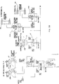
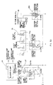
- a hydraulic system 60 is depicted in Figures 5A through 5D.
- This system includes a suction reservoir 62, a recirculating pump 64, a tool bath tank 66, a large reservoir 63, a collar 65, and other motors and pumps, all for storing and conveying hydroforming liquid, typically water, to various parts of the system.
- Downstream from pump 64 is a first single stage pressure intensifier 68 for a workpiece in the preform and semi-finish cavity 14, and a second pressure intensifier 70 for a workpiece in the finish cavity 16.
- a solenoid actuated valve 68A controls the output from intensifier 68 while a solenoid actuated valve 70A controls the output from intensifier 70.
- These valves 68A and 70A may be actuated in response to pressure sensors.
- the solenoid valve 70A for intensifier 70 will actuate to allow intensified liquid pressure to be applied to the workpiece in cavity 16, such that there is a time overlapping of the hydroforming steps for the two workpieces. This saves considerable production time.
- the end plugs 20 for the semi-finish cavity are also linked into the hydraulic system through solenoid valve 20A.
- the end plugs 40 for the finish cavity 16 are linked into the hydraulic system through solenoid valve 40A.
- the shuttle cylinder 15 is connected to the hydraulic system through solenoid valve 15'.
- This cylinder 15 is preferably of the known so-called "smart cylinder” type, including a pressure sensor 15B which detects any unplanned pressure increase of the cylinder due to an obstruction, e.g., the mold being partly open, to immediately stop the cylinder action to prevent damage to the equipment.
- Cylinders 27 also are preferably of this " smart cylinder” type and include controllers 27A which allow bleeding off of hydraulic liquid from the cylinders, while keeping the cylinder pressure constant, when the mold assembly is being retracted into the clamp; and allowing liquid entry into the cylinders when the mold assembly is being transferred out of the clamp. These controls also stop the system in the event that some excessive pressure is encountered, e.g., by mold closing or something inadvertently left between the two mold elements.
- a pair of cylinders 127 can extend between the upper mold element 23 and the carriage or slide 13 on opposite sides of the mold.
- the cylinders 127 would not need the controlled release of fluid during advancement of the carriage between the platen as do cylinders 27.
- the programming control of the apparatus would be simpler.
- the bladder clamp subassembly 25 is controlled through its valves 25'.
- the tube seal cylinders 24 are controlled by solenoid valve 24A. If part ejectors and their cylinders are employed as at 72 to lift workpieces from the cavities 14 and 16, then solenoid valve 72A is utilised to connect them with the hydraulic system and to control their operation.
- safety lock pins can also be employed as shown at 74, to lock the mold assembly open, these being controlled by solenoid valve 74.
- the initial workpiece to be hydroform-expanded compresses an inner, metal, preferably steel, and most preferably stainless steel, tube or tubular element 50, and an outer tubular element 52, also of metal, and preferably steel, most preferably stainless steel (Figure 9).
- the inner diameter of outer tube element 52 basically coincides with the outer diameter of inner tube element 50 such that normally the initial workpiece has 360° contact between the two elements along the length thereof.
- the inner element has at least one opening 54 extending through its wall thickness from the inner cavity 56 defined by the inner element to the inner wall of the outer element.
- the one or more openings, and preferably two, along the length of the inner element are located only either adjacent one end or both ends, preferably both ends, of the inner element, spaced from the open ends of the element an amount to be inward of the tapered noses 22 when in the first cavity, and inward of tapered noses 42 when in the second cavity.
- the tube elements of the initial workpiece are typically cylindrical in configuration, not yet having the flared end portions depicted in the drawings. Conceivably, however, the ends could be previously flared prior to placement in the first hydroforming cavity, e.g., when the tubes are pulled or rammed together or when the double tube is bent to effect any desired nonlinear configuration or angles therein.
- the opposite ends 16' of cavity 16 are outwardly tapered to match the configuration and angle of the tapered noses 42.
- the opposite ends of cavity 14 may also have outwardly flared portions matching those of the tapered noses 22.
- the purpose of the two-stage hydroforming operation is to first expand or enlarge both the inner and outer tube elements simultaneously by hydroforming in first cavity 14, and thereby obtain a predetermined final inner tube dimension, and then subsequently to expand or enlarge by hydroforming only the outer element further, while not changing the size of the inner element, using the second cavity 16.
- This workpiece is at least mostly of smaller outside diameter than the diameter of cavity 14 and is laid in the lower part of the cavity 14, and the top mold member is brought down to interfit with the lower mold member. During this closing, portions of the workpiece can be partially mechanically formed by the walls of cavity 14 acting as a die, as noted previously. The mold assembly is then shifted into the hydroforming station beneath crown 11C.
- a very large force is then applied by diaphragms 33 to hold the mold assembly totally closed and immovable during the hydroforming operation.
- fluid actuators 25 are shifted axially to extend the first end plug subassemblies 20 into the workpiece W in cavity 14.
- the tapered nose elements 42 are forced toward cavity 14, thereby engaging the cylindrical ends of workpiece W and flaring them outwardly as the tapered noses extend to their final position partially within cavity 14. This flaring also enables the workpiece to be held on centre in this cavity and also in the subsequent cavity 16.
- actuator 25 inserts nose 22, it also inserts seal 28 into cavity 14 and the workpiece therein a predetermined distance, past the openings 54 of inner tube 50.
- the second power actuators 24 are then actuated to axially extend collar 34 a small amount, thereby axially compressing the resilient annular seals 28. This causes them to radially expand into tight engagement with the ends of the inner peripheral wall of inner tube element 50, as well as rod 30, to tightly seal the ends of the inner workpiece cavity 56 axially inwardly of openings 543. Hydroforming liquid is then injected through liquid conduit 26 in at least one of the end plug subassemblies to fill space 56.
- the hydroforming process is preferably performed in a bath of liquid, e.g., water, so as to be submerged.
- liquid e.g., water
- filling of the workpiece will occur with submersion of the workpiece so that only a small amount of added liquid under pressure through passage 26 will be necessary for hydroforming.
- Sufficient hydroforming pressure is then built up in the liquid inside the workpiece over a period of several seconds to a high value to simultaneously expand both the inner and outer tubular elements 50 and 52 until the outer element outer surface takes the configuration and size of cavity 14, and to give the inner element its desired final dimension.
- any flows e.g., in the weld of the longitudinal seam of inner element 50, can be detected since the pressurized liquid inside cavity 56 will tend to flow through any flaw in inner element 50 to be between tube elements 50 and 52 and thus cause a profile pressure curve to be generated in a different pattern because of the reduced resistance to forming with just the outer metal.
- pressure would drop noticeably or cease to build.
- This first step thus acts as an excellent quality check, even on the inner element.
- the pressure is then decreased over the next couple of seconds in the workpiece in this first cavity 14, it is increased over those same seconds in the workpiece in the second cavity 16. Thus, there is an overlap of the time which shortens the total time necessary.
- Initiation of the second cavity increase is controlled in response to pressure sensors on the first hydroforming system.
- seals 28 are caused to readily retract by retracting collar 34 axially, and the end plugs with tapered noses 22 and seals are retracted from the modified workpiece W' and cavity 14. There is no need to drain the workpiece when it is transferred over to second cavity 16.
- the diameter, of the second cavity is greater than that of the first cavity, there will be a gap between the outer wall of the partially expanded workpiece W' therein and the peripheral wall of the second cavity.
- the end plug subassemblies 40 when axially extended, cause the second pair of tapered noses 42 to engage the flared end portions of the workpiece to thereby enter it in cavity 16.
- the tapered noses 42 of the second pair of end plug subassemblies 40 are inserted into cavity 16 and the partially expanded workpiece W' with sufficient force to press the flared ends of inner and outer elements 50 and 52 tightly together to create a seal between them. This is to prevent hydroforming liquid from escaping between the two tube elements during the second hydroforming operation.
- openings 54 are now exposed to the entire inner cavity 56 of the workpiece. It will be realised that these steps will have been performed generally prior to or during hydroforming pressure increase on the workpiece in the first cavity 14 so that the workpiece in cavity 16 is ready to be pressurised.
- hydroforming pressure is applied in the workpiece in cavity 16
- the liquid through openings 54 will cause the pressure on both the inner wall and the outer wall of inner element 50 to be equal, but a significant outward force to be applied to the inside wall of outer element 52, causing it to expand to the finish dimensions of cavity 16, giving the outer element its desired dimensions and controlled accurate spacing from the inner element.
- the pressure is controllably decreased and released from the finished workpiece in cavity 16.
- the hydroforming liquid is subsequently drained out of the finished workpiece, the empty the workpiece of liquid.
- the entire hydroforming operation requires only a fraction of a minute so that production rates can be significantly high.
- the offal at the ends of the workpiece, i.e., the flared end portions can ultimately be severed to leave the finished conduit product.
- Each workpiece and each mold cavity can also be configured to form a multiple e.g., two or more, of the desired final product, so that by cutting the finished product into two like pieces, production can be even further increased.
Landscapes
- Engineering & Computer Science (AREA)
- Mechanical Engineering (AREA)
- Physics & Mathematics (AREA)
- Fluid Mechanics (AREA)
- Shaping Metal By Deep-Drawing, Or The Like (AREA)
- Electrical Discharge Machining, Electrochemical Machining, And Combined Machining (AREA)
- Exhaust Silencers (AREA)
Applications Claiming Priority (2)
| Application Number | Priority Date | Filing Date | Title |
|---|---|---|---|
| US241740 | 1988-09-08 | ||
| US08/241,740 US5582052A (en) | 1993-05-20 | 1994-05-12 | Controlled time-overlapped hydroforming |
Publications (2)
| Publication Number | Publication Date |
|---|---|
| EP0686440A1 true EP0686440A1 (fr) | 1995-12-13 |
| EP0686440B1 EP0686440B1 (fr) | 1999-01-13 |
Family
ID=22911983
Family Applications (1)
| Application Number | Title | Priority Date | Filing Date |
|---|---|---|---|
| EP95303106A Expired - Lifetime EP0686440B1 (fr) | 1994-05-12 | 1995-05-09 | Dispositif pour hydroformage |
Country Status (6)
| Country | Link |
|---|---|
| US (2) | US5582052A (fr) |
| EP (1) | EP0686440B1 (fr) |
| JP (1) | JPH08187523A (fr) |
| AT (1) | ATE175598T1 (fr) |
| DE (1) | DE69507201T2 (fr) |
| ES (1) | ES2128662T3 (fr) |
Cited By (13)
| Publication number | Priority date | Publication date | Assignee | Title |
|---|---|---|---|---|
| EP0858849A1 (fr) * | 1997-02-12 | 1998-08-19 | Anton Bauer Werkzeug- und Maschinenbau GmbH & Co. KG | Dispositif de tension pour un outil de formage interne à haute pression |
| EP0865845A1 (fr) * | 1997-03-22 | 1998-09-23 | WDB Ringwalztechnik GmbH | Procédé pour maintenir ensemble moules ou matrices en deux parties soumises à pression interne et dispositif pour la mise en oeuvre du procédé |
| WO1999058266A1 (fr) * | 1998-05-11 | 1999-11-18 | Automation, Press And Tooling Ap & T Ab | Appareil et procede destines a l'hydroformage de pieces |
| US5992197A (en) * | 1997-03-28 | 1999-11-30 | The Budd Company | Forming technique using discrete heating zones |
| US6006568A (en) * | 1998-03-20 | 1999-12-28 | The Budd Company | Multi-piece hydroforming tool |
| US6032501A (en) * | 1999-02-09 | 2000-03-07 | The Budd Company | Method of hydroforming multi-lateral members from round tubes |
| WO2001036123A1 (fr) * | 1999-11-17 | 2001-05-25 | Industriellt Utvecklingscenter Dalarna Ab | Ensemble outil |
| EP1138410A3 (fr) * | 2000-03-31 | 2002-05-08 | Dana Corporation | Dispositif pour le formage à haute pression interne |
| US6536251B2 (en) | 2000-03-31 | 2003-03-25 | Dana Corporation | Apparatus for performing hydroforming operation |
| EP1442806A1 (fr) * | 2003-01-31 | 2004-08-04 | Bourgogne Hydro Technologie | Dispositif d'hydroformage d'un corps creux |
| US6889535B1 (en) | 1999-11-17 | 2005-05-10 | Hyfotec Sweden Ab | Tool assembly |
| US7047780B2 (en) | 2001-06-29 | 2006-05-23 | Dana Corporation | Apparatus for performing a hydroforming operation |
| CN112605220A (zh) * | 2020-11-27 | 2021-04-06 | 四川航天长征装备制造有限公司 | 一种大径厚比超薄管材充液压弯模具组及成型方法 |
Families Citing this family (33)
| Publication number | Priority date | Publication date | Assignee | Title |
|---|---|---|---|---|
| FR2744380B1 (fr) * | 1996-02-06 | 1998-08-28 | Bas En Basset Soc Ind De | Installation pour la fabrication de pieces par hydroflambage |
| GB2340779B (en) * | 1997-05-12 | 2001-03-14 | Dana Corp | Method of hydroforming a vehicle frame component |
| UY25199A1 (es) * | 1997-10-07 | 1999-04-07 | Cosma Int Inc | Metodo y aparato para hidroformacion sin arrugas de componentes tubulares oblicuos |
| US6533348B1 (en) | 1997-10-16 | 2003-03-18 | Cosma International Inc. | Modular space frame |
| US6623067B2 (en) | 1997-10-16 | 2003-09-23 | Magna International Inc. | Door seal interface structure for a motor vehicle space frame |
| US6689982B2 (en) | 1997-10-16 | 2004-02-10 | Magna International, Inc. | Apparatus and method for welding aluminum tubes |
| US6621037B2 (en) | 1997-10-16 | 2003-09-16 | Magna International Inc. | Welding material with conductive sheet and method |
| US6713707B2 (en) | 1997-10-16 | 2004-03-30 | Magna International, Inc. | Welding material and method without carrier |
| US6346684B1 (en) | 1997-10-16 | 2002-02-12 | Cosma International Inc. | Welding material assembly and method |
| US6302478B1 (en) | 1997-10-16 | 2001-10-16 | Cosma International Inc. | Hydroformed space frame joints therefor |
| ATE205794T1 (de) * | 1997-10-16 | 2001-10-15 | Cosma Int Inc | Durch innenhochdruck geformtes raumfachwerk und verfahren zu dessen herstellung |
| DE19752773C2 (de) * | 1997-11-28 | 1999-09-02 | Daimler Chrysler Ag | Verfahren zur Herstellung eines luftspaltisolierten Abgaskrümmers einer Fahrzeugabgasanlage |
| DE19752772C2 (de) | 1997-11-28 | 1999-09-02 | Daimler Chrysler Ag | Verfahren zur Herstellung eines mit einem Abzweigstutzen versehenen luftspaltisolierten Abgasrohres |
| DE19809746A1 (de) * | 1998-03-06 | 1999-09-16 | Benteler Werke Ag | Vorrichtung zur hydraulischen Umformung von metallischen Hohlkörpern |
| US6098437A (en) * | 1998-03-20 | 2000-08-08 | The Budd Company | Hydroformed control arm |
| US6183013B1 (en) | 1999-07-26 | 2001-02-06 | General Motors Corporation | Hydroformed side rail for a vehicle frame and method of manufacture |
| US6209372B1 (en) | 1999-09-20 | 2001-04-03 | The Budd Company | Internal hydroformed reinforcements |
| US6566624B2 (en) | 2000-03-03 | 2003-05-20 | Magna International Inc. | Welding assembly with nestable conductive ends |
| CA2350731C (fr) * | 2000-06-16 | 2004-12-07 | Toyota Jidosha Kabushiki Kaisha | Appareil et methode de verrouillage de moules |
| CN100368109C (zh) * | 2001-05-22 | 2008-02-13 | 三菱自动车工业株式会社 | 液压成形产品 |
| US6510720B1 (en) * | 2001-10-18 | 2003-01-28 | Hartwick Professionals, Inc. | Hydraulic pressure forming using a self aligning and activating die system |
| JP2006026654A (ja) * | 2004-07-13 | 2006-02-02 | Suzuki Motor Corp | ハイドロフォーム成形方法及びハイドロフォーム成形装置 |
| JP4469775B2 (ja) * | 2004-10-05 | 2010-05-26 | ダッソー システムズ ソリッドワークス コーポレイション | 公差スキームの自動生成 |
| SE529034C2 (sv) * | 2005-08-04 | 2007-04-17 | Hydroforming Design Light Ab | Anordning och förfarande för att hålla samman två verktygshalvor under en hydroformningsprocess |
| US7251973B2 (en) * | 2005-09-12 | 2007-08-07 | Gharib Mohamed T | Hydroforming apparatus |
| KR100851828B1 (ko) * | 2006-11-08 | 2008-08-13 | 현대자동차주식회사 | U자형 제품 제작을 위한 하이드로 포밍 장치 |
| JP4941054B2 (ja) | 2007-03-30 | 2012-05-30 | 住友金属工業株式会社 | 継目無ベンド管の製造方法並びに溶接継手及びその製造方法 |
| JP5668698B2 (ja) * | 2012-01-24 | 2015-02-12 | 新日鐵住金株式会社 | 管材成形装置及び方法 |
| JP6240564B2 (ja) * | 2014-06-19 | 2017-11-29 | 住友重機械工業株式会社 | 成形装置及び成形装置の部品の交換方法 |
| RU2564655C1 (ru) * | 2014-07-09 | 2015-10-10 | Открытое акционерное общество "Научно-производственное объединение "Сатурн" | Устройство для газостатической формовки полых заготовок |
| US10220430B2 (en) * | 2015-10-12 | 2019-03-05 | Ali Sadri | Method of fabricating a one-piece metal vehicle wheel by hydro forming process |
| US10722932B2 (en) * | 2015-10-12 | 2020-07-28 | Ali Sadri | Method of fabricating a one-piece metal vehicle wheel by hydro forming process |
| CN117259545B (zh) * | 2023-02-20 | 2026-03-17 | 南皮县安德五金制造有限公司 | 一种用于拉深的钢性压边装置 |
Citations (5)
| Publication number | Priority date | Publication date | Assignee | Title |
|---|---|---|---|---|
| DE2625424A1 (de) * | 1975-06-24 | 1977-01-20 | Asea Ab | Hydraulische presse |
| DE4019899C1 (fr) * | 1990-06-22 | 1991-12-19 | Benteler Ag, 4790 Paderborn, De | |
| EP0494843A1 (fr) * | 1991-01-11 | 1992-07-15 | Scambia Industrial Developments Aktiengesellschaft | Procédé de fabrication d'une pièce tubulaire à parois double . |
| US5170557A (en) * | 1991-05-01 | 1992-12-15 | Benteler Industries, Inc. | Method of forming a double wall, air gap exhaust duct component |
| DE4312589A1 (de) * | 1992-10-27 | 1994-04-28 | Rexroth Mannesmann Gmbh | Hydraulisches System für eine Umformpresse |
Family Cites Families (28)
| Publication number | Priority date | Publication date | Assignee | Title |
|---|---|---|---|---|
| US1879009A (en) * | 1930-05-07 | 1932-09-27 | Benjamin F Anthony | Apparatus for finishing and testing tubular products |
| US2138268A (en) * | 1936-08-17 | 1938-11-29 | Campbell Wyant & Cannon Co | Brake drum machine |
| US2667136A (en) * | 1950-08-11 | 1954-01-26 | Hydropress Inc | Hydraulic machine |
| US3266086A (en) * | 1963-05-01 | 1966-08-16 | Arnav Ind Inc | Molding apparatus |
| DE1579117A1 (de) * | 1964-01-11 | 1970-01-29 | Continental Gummi Werke Ag | Einrichtung zur Herstellung von Kautschukartikeln |
| DE2060346A1 (de) * | 1969-12-09 | 1971-06-09 | Aoki K | Verfahren und Vorrichtung zum Herstellen von Spritzgussformlingen |
| DE2027934A1 (en) * | 1970-06-06 | 1971-12-16 | Volkswagenwerk Ag | Mould clamping device - with air cushion between clamping mould - and mould outer wall |
| US3663027A (en) * | 1970-09-14 | 1972-05-16 | Ingersoll Milling Machine Co | Fluid actuated clamp |
| US3691266A (en) * | 1970-12-08 | 1972-09-12 | Regal China Corp | Supporting carriage for,and method of casting in,molds for the production of ceramic hollow ware |
| GB1343405A (en) * | 1971-07-23 | 1974-01-10 | Foster Yates Thom Ltd | Moulding machines |
| US3947196A (en) * | 1974-03-28 | 1976-03-30 | The French Oil Mill Machinery Company | Injection molding apparatus |
| DE2750867C2 (de) * | 1977-11-14 | 1983-10-20 | Benteler-Werke Ag Werk Neuhaus, 4790 Paderborn | Verwendung einer Stahllegierung für Rohre zur Türverstärkung |
| DE3004838C2 (de) * | 1980-02-09 | 1984-09-13 | Benteler-Werke Ag Werk Neuhaus, 4790 Paderborn | Vorrichtung zur Herstellung eines Rohrkörpers mit Querwellen |
| DE3249342C2 (de) * | 1982-02-02 | 1986-08-14 | Fiziko-techničeskij institut Akademii Nauk Belorusskoj SSR, Minsk | Einrichtung zum Formgebung von Rohren durch Fl}ssigkeitstossdruck |
| US4708390A (en) * | 1985-11-15 | 1987-11-24 | Benteler Corporation | Laser contour cut door beams |
| US4636608A (en) * | 1985-11-15 | 1987-01-13 | Benteler Corporation | Laser contour cut door beams |
| US4644128A (en) * | 1986-01-21 | 1987-02-17 | Benteler Corporation | Laser contour cut manifolds |
| US4798076A (en) * | 1988-02-26 | 1989-01-17 | Benteler Industries, Inc. | Nipple forming apparatus |
| US5481892A (en) * | 1989-08-24 | 1996-01-09 | Roper; Ralph E. | Apparatus and method for forming a tubular member |
| CA2023675C (fr) * | 1989-08-24 | 2001-07-31 | Ralph E. Roper | Methode et dispositif de formage d'un element tubulaire pour chassis |
| DE4017072A1 (de) * | 1990-05-26 | 1991-11-28 | Benteler Werke Ag | Verfahren zum hydraulischen umformen eines rohrfoermigen hohlkoerpers und vorrichtung zur durchfuehrung des verfahrens |
| US5118159A (en) * | 1990-12-19 | 1992-06-02 | Benteler Industries, Inc. | Optimized moment capacity nestable door beam |
| US5123694A (en) * | 1991-06-19 | 1992-06-23 | Benteler Industries, Inc. | Spiral taper cut impact beam |
| US5363544A (en) * | 1993-05-20 | 1994-11-15 | Benteler Industries, Inc. | Multi-stage dual wall hydroforming |
| IT1261585B (it) * | 1993-09-10 | 1996-05-23 | G S Gilardini Silenziamento Sr | Sistema di scarico per un motore a combustione interna di autoveicolo,e procedimento per la produzione di tale sistema |
| US5415021A (en) * | 1993-10-29 | 1995-05-16 | Folmer; Carroll W. | Apparatus for high pressure hydraulic forming of sheet metal blanks, flat patterns, and piping |
| US5471857A (en) * | 1994-03-07 | 1995-12-05 | Mascotech Tubular Products, Inc. | Process for hydroforming a vehicle manifold |
| US5445001A (en) * | 1994-08-10 | 1995-08-29 | General Motors Corporation | Method and apparatus for forming and cutting tubing |
-
1994
- 1994-05-12 US US08/241,740 patent/US5582052A/en not_active Expired - Lifetime
-
1995
- 1995-04-28 JP JP7141057A patent/JPH08187523A/ja not_active Ceased
- 1995-05-09 EP EP95303106A patent/EP0686440B1/fr not_active Expired - Lifetime
- 1995-05-09 ES ES95303106T patent/ES2128662T3/es not_active Expired - Lifetime
- 1995-05-09 AT AT95303106T patent/ATE175598T1/de not_active IP Right Cessation
- 1995-05-09 DE DE69507201T patent/DE69507201T2/de not_active Expired - Lifetime
- 1995-11-21 US US08/560,798 patent/US5600983A/en not_active Expired - Lifetime
Patent Citations (5)
| Publication number | Priority date | Publication date | Assignee | Title |
|---|---|---|---|---|
| DE2625424A1 (de) * | 1975-06-24 | 1977-01-20 | Asea Ab | Hydraulische presse |
| DE4019899C1 (fr) * | 1990-06-22 | 1991-12-19 | Benteler Ag, 4790 Paderborn, De | |
| EP0494843A1 (fr) * | 1991-01-11 | 1992-07-15 | Scambia Industrial Developments Aktiengesellschaft | Procédé de fabrication d'une pièce tubulaire à parois double . |
| US5170557A (en) * | 1991-05-01 | 1992-12-15 | Benteler Industries, Inc. | Method of forming a double wall, air gap exhaust duct component |
| DE4312589A1 (de) * | 1992-10-27 | 1994-04-28 | Rexroth Mannesmann Gmbh | Hydraulisches System für eine Umformpresse |
Cited By (16)
| Publication number | Priority date | Publication date | Assignee | Title |
|---|---|---|---|---|
| US6182488B1 (en) | 1997-02-12 | 2001-02-06 | Anton Bauer Werkzeug-Und Maschinenbau Gmbh & Co. Kg | Tensioning device for an internal high-pressure forming tool |
| EP0858849A1 (fr) * | 1997-02-12 | 1998-08-19 | Anton Bauer Werkzeug- und Maschinenbau GmbH & Co. KG | Dispositif de tension pour un outil de formage interne à haute pression |
| EP0865845A1 (fr) * | 1997-03-22 | 1998-09-23 | WDB Ringwalztechnik GmbH | Procédé pour maintenir ensemble moules ou matrices en deux parties soumises à pression interne et dispositif pour la mise en oeuvre du procédé |
| US5992197A (en) * | 1997-03-28 | 1999-11-30 | The Budd Company | Forming technique using discrete heating zones |
| US6006568A (en) * | 1998-03-20 | 1999-12-28 | The Budd Company | Multi-piece hydroforming tool |
| US6354125B1 (en) | 1998-05-11 | 2002-03-12 | Automation, Press And Tooling Ap&T Ab | Apparatus and method for hydroforming workpieces |
| WO1999058266A1 (fr) * | 1998-05-11 | 1999-11-18 | Automation, Press And Tooling Ap & T Ab | Appareil et procede destines a l'hydroformage de pieces |
| US6032501A (en) * | 1999-02-09 | 2000-03-07 | The Budd Company | Method of hydroforming multi-lateral members from round tubes |
| WO2001036123A1 (fr) * | 1999-11-17 | 2001-05-25 | Industriellt Utvecklingscenter Dalarna Ab | Ensemble outil |
| US6889535B1 (en) | 1999-11-17 | 2005-05-10 | Hyfotec Sweden Ab | Tool assembly |
| EP1138410A3 (fr) * | 2000-03-31 | 2002-05-08 | Dana Corporation | Dispositif pour le formage à haute pression interne |
| US6536251B2 (en) | 2000-03-31 | 2003-03-25 | Dana Corporation | Apparatus for performing hydroforming operation |
| US7047780B2 (en) | 2001-06-29 | 2006-05-23 | Dana Corporation | Apparatus for performing a hydroforming operation |
| EP1442806A1 (fr) * | 2003-01-31 | 2004-08-04 | Bourgogne Hydro Technologie | Dispositif d'hydroformage d'un corps creux |
| FR2850593A1 (fr) * | 2003-01-31 | 2004-08-06 | Bourgogne Hydro Technologie | Dispositif d'hydroformage d'un corps creux |
| CN112605220A (zh) * | 2020-11-27 | 2021-04-06 | 四川航天长征装备制造有限公司 | 一种大径厚比超薄管材充液压弯模具组及成型方法 |
Also Published As
| Publication number | Publication date |
|---|---|
| ATE175598T1 (de) | 1999-01-15 |
| DE69507201D1 (de) | 1999-02-25 |
| US5600983A (en) | 1997-02-11 |
| ES2128662T3 (es) | 1999-05-16 |
| DE69507201T2 (de) | 1999-06-24 |
| US5582052A (en) | 1996-12-10 |
| EP0686440B1 (fr) | 1999-01-13 |
| JPH08187523A (ja) | 1996-07-23 |
Similar Documents
| Publication | Publication Date | Title |
|---|---|---|
| EP0686440B1 (fr) | Dispositif pour hydroformage | |
| EP1017516B1 (fr) | Appareil d'hydroformage et procede correspondant | |
| US6154944A (en) | Method for expansion forming of tubing | |
| US5499520A (en) | Apparatus for forming a tubular frame member | |
| JP2997909B2 (ja) | 多段2重壁ハイドロフォ−ミング | |
| EP0414545A2 (fr) | Dispositif et procédé pour former un cadre tubulaire | |
| KR100517584B1 (ko) | 하이드로폼 성형된 각진 관형 부품 및 이를 제조하기 위한방법 및 장치 | |
| JP3206505B2 (ja) | 金属管の液圧バルジ加工方法および液圧バルジ加工装置 | |
| GB2029747A (en) | Apparatus for fabricating spiral wrapped cartidge cases | |
| JPH06292929A (ja) | 管状フレーム部材を成形し且つ液圧穴抜き加工する装置及び方法 | |
| US6305204B1 (en) | Bulge forming machine | |
| CN1199746C (zh) | 一种胀形方法及其实现该胀形方法的装置 | |
| JP4416887B2 (ja) | パイプ材のハイドロフォーミング装置 | |
| US6662611B2 (en) | Hydroforming flush system | |
| US7392679B1 (en) | Hydroform tube sealing assembly | |
| WO2000000309A1 (fr) | Dispositif et procede destines au formage par deploiement | |
| MXPA02002640A (es) | Metodo para hidroformar un carril de combustible para un sistema de suministro de combustible a vehiculos. | |
| WO2000048761A1 (fr) | Procede d'obturation et appareil a presse | |
| US6009734A (en) | Process and device for manufacturing hollow sections with end-side cross-sectional expansions | |
| WO2003033187A1 (fr) | Formage a pression hydraulique utilisant un systeme de moules a alignement et activation autonomes | |
| US20060065031A1 (en) | Method for performing a hydroforming operation | |
| JPH10296367A (ja) | 金属中空体のストレッチ成形方法 | |
| WO1998043758A1 (fr) | Procede de faconnage de tuyauterie et appareil correspondant | |
| EP1098721B1 (fr) | Matrice de formage de tube par hydrocompression et son procede de production | |
| EP0961683A1 (fr) | Dispositif permettant de maintenir un flan dans une presse a cellule remplie de fluide et presse a cellule remplie de fluide |
Legal Events
| Date | Code | Title | Description |
|---|---|---|---|
| PUAI | Public reference made under article 153(3) epc to a published international application that has entered the european phase |
Free format text: ORIGINAL CODE: 0009012 |
|
| AK | Designated contracting states |
Kind code of ref document: A1 Designated state(s): AT BE CH DE DK ES FR GB GR IE IT LI LU MC NL PT SE |
|
| 17P | Request for examination filed |
Effective date: 19960531 |
|
| GRAG | Despatch of communication of intention to grant |
Free format text: ORIGINAL CODE: EPIDOS AGRA |
|
| 17Q | First examination report despatched |
Effective date: 19980406 |
|
| GRAG | Despatch of communication of intention to grant |
Free format text: ORIGINAL CODE: EPIDOS AGRA |
|
| GRAG | Despatch of communication of intention to grant |
Free format text: ORIGINAL CODE: EPIDOS AGRA |
|
| GRAH | Despatch of communication of intention to grant a patent |
Free format text: ORIGINAL CODE: EPIDOS IGRA |
|
| GRAH | Despatch of communication of intention to grant a patent |
Free format text: ORIGINAL CODE: EPIDOS IGRA |
|
| GRAA | (expected) grant |
Free format text: ORIGINAL CODE: 0009210 |
|
| AK | Designated contracting states |
Kind code of ref document: B1 Designated state(s): AT BE CH DE DK ES FR GB GR IE IT LI LU MC NL PT SE |
|
| PG25 | Lapsed in a contracting state [announced via postgrant information from national office to epo] |
Ref country code: SE Free format text: THE PATENT HAS BEEN ANNULLED BY A DECISION OF A NATIONAL AUTHORITY Effective date: 19990113 Ref country code: GR Free format text: LAPSE BECAUSE OF NON-PAYMENT OF DUE FEES Effective date: 19990113 |
|
| REF | Corresponds to: |
Ref document number: 175598 Country of ref document: AT Date of ref document: 19990115 Kind code of ref document: T |
|
| REG | Reference to a national code |
Ref country code: CH Ref legal event code: EP |
|
| REG | Reference to a national code |
Ref country code: CH Ref legal event code: NV Representative=s name: KIRKER & CIE SA |
|
| REG | Reference to a national code |
Ref country code: IE Ref legal event code: FG4D |
|
| REF | Corresponds to: |
Ref document number: 69507201 Country of ref document: DE Date of ref document: 19990225 |
|
| ET | Fr: translation filed | ||
| ITF | It: translation for a ep patent filed | ||
| PG25 | Lapsed in a contracting state [announced via postgrant information from national office to epo] |
Ref country code: PT Free format text: LAPSE BECAUSE OF FAILURE TO SUBMIT A TRANSLATION OF THE DESCRIPTION OR TO PAY THE FEE WITHIN THE PRESCRIBED TIME-LIMIT Effective date: 19990413 Ref country code: DK Free format text: LAPSE BECAUSE OF FAILURE TO SUBMIT A TRANSLATION OF THE DESCRIPTION OR TO PAY THE FEE WITHIN THE PRESCRIBED TIME-LIMIT Effective date: 19990413 |
|
| REG | Reference to a national code |
Ref country code: ES Ref legal event code: FG2A Ref document number: 2128662 Country of ref document: ES Kind code of ref document: T3 |
|
| PLBE | No opposition filed within time limit |
Free format text: ORIGINAL CODE: 0009261 |
|
| STAA | Information on the status of an ep patent application or granted ep patent |
Free format text: STATUS: NO OPPOSITION FILED WITHIN TIME LIMIT |
|
| PG25 | Lapsed in a contracting state [announced via postgrant information from national office to epo] |
Ref country code: MC Free format text: LAPSE BECAUSE OF NON-PAYMENT OF DUE FEES Effective date: 19991130 |
|
| 26N | No opposition filed | ||
| REG | Reference to a national code |
Ref country code: GB Ref legal event code: IF02 |
|
| PGFP | Annual fee paid to national office [announced via postgrant information from national office to epo] |
Ref country code: LU Payment date: 20040325 Year of fee payment: 10 |
|
| PGFP | Annual fee paid to national office [announced via postgrant information from national office to epo] |
Ref country code: IE Payment date: 20040406 Year of fee payment: 10 Ref country code: AT Payment date: 20040406 Year of fee payment: 10 |
|
| PGFP | Annual fee paid to national office [announced via postgrant information from national office to epo] |
Ref country code: NL Payment date: 20040413 Year of fee payment: 10 |
|
| PGFP | Annual fee paid to national office [announced via postgrant information from national office to epo] |
Ref country code: BE Payment date: 20040603 Year of fee payment: 10 |
|
| PGFP | Annual fee paid to national office [announced via postgrant information from national office to epo] |
Ref country code: CH Payment date: 20040608 Year of fee payment: 10 |
|
| PG25 | Lapsed in a contracting state [announced via postgrant information from national office to epo] |
Ref country code: LU Free format text: LAPSE BECAUSE OF NON-PAYMENT OF DUE FEES Effective date: 20050509 Ref country code: IE Free format text: LAPSE BECAUSE OF NON-PAYMENT OF DUE FEES Effective date: 20050509 Ref country code: AT Free format text: LAPSE BECAUSE OF NON-PAYMENT OF DUE FEES Effective date: 20050509 |
|
| PG25 | Lapsed in a contracting state [announced via postgrant information from national office to epo] |
Ref country code: LI Free format text: LAPSE BECAUSE OF NON-PAYMENT OF DUE FEES Effective date: 20050531 Ref country code: CH Free format text: LAPSE BECAUSE OF NON-PAYMENT OF DUE FEES Effective date: 20050531 Ref country code: BE Free format text: LAPSE BECAUSE OF NON-PAYMENT OF DUE FEES Effective date: 20050531 |
|
| BERE | Be: lapsed |
Owner name: *BENTELER INDUSTRIES INC. Effective date: 20050531 |
|
| PG25 | Lapsed in a contracting state [announced via postgrant information from national office to epo] |
Ref country code: NL Free format text: LAPSE BECAUSE OF NON-PAYMENT OF DUE FEES Effective date: 20051201 |
|
| REG | Reference to a national code |
Ref country code: CH Ref legal event code: PL |
|
| NLV4 | Nl: lapsed or anulled due to non-payment of the annual fee |
Effective date: 20051201 |
|
| REG | Reference to a national code |
Ref country code: IE Ref legal event code: MM4A |
|
| PGFP | Annual fee paid to national office [announced via postgrant information from national office to epo] |
Ref country code: IT Payment date: 20060531 Year of fee payment: 12 |
|
| PGFP | Annual fee paid to national office [announced via postgrant information from national office to epo] |
Ref country code: ES Payment date: 20070528 Year of fee payment: 13 |
|
| PGFP | Annual fee paid to national office [announced via postgrant information from national office to epo] |
Ref country code: GB Payment date: 20070410 Year of fee payment: 13 |
|
| BERE | Be: lapsed |
Owner name: *BENTELER INDUSTRIES INC. Effective date: 20050531 |
|
| PGFP | Annual fee paid to national office [announced via postgrant information from national office to epo] |
Ref country code: FR Payment date: 20070503 Year of fee payment: 13 |
|
| GBPC | Gb: european patent ceased through non-payment of renewal fee |
Effective date: 20080509 |
|
| REG | Reference to a national code |
Ref country code: FR Ref legal event code: ST Effective date: 20090119 |
|
| PG25 | Lapsed in a contracting state [announced via postgrant information from national office to epo] |
Ref country code: FR Free format text: LAPSE BECAUSE OF NON-PAYMENT OF DUE FEES Effective date: 20080602 |
|
| PG25 | Lapsed in a contracting state [announced via postgrant information from national office to epo] |
Ref country code: GB Free format text: LAPSE BECAUSE OF NON-PAYMENT OF DUE FEES Effective date: 20080509 |
|
| REG | Reference to a national code |
Ref country code: ES Ref legal event code: FD2A Effective date: 20080510 |
|
| PG25 | Lapsed in a contracting state [announced via postgrant information from national office to epo] |
Ref country code: IT Free format text: LAPSE BECAUSE OF NON-PAYMENT OF DUE FEES Effective date: 20070509 |
|
| PG25 | Lapsed in a contracting state [announced via postgrant information from national office to epo] |
Ref country code: ES Free format text: LAPSE BECAUSE OF NON-PAYMENT OF DUE FEES Effective date: 20080510 |
|
| PGFP | Annual fee paid to national office [announced via postgrant information from national office to epo] |
Ref country code: DE Payment date: 20140529 Year of fee payment: 20 |
|
| REG | Reference to a national code |
Ref country code: DE Ref legal event code: R071 Ref document number: 69507201 Country of ref document: DE |
|
| REG | Reference to a national code |
Ref country code: DE Ref legal event code: R071 Ref document number: 69507201 Country of ref document: DE |