EP0686751A1 - Verbesserung an Mitteln für Befestigung und Halterung von in die Verglasung integrierte Struktur - Google Patents
Verbesserung an Mitteln für Befestigung und Halterung von in die Verglasung integrierte Struktur Download PDFInfo
- Publication number
- EP0686751A1 EP0686751A1 EP95401338A EP95401338A EP0686751A1 EP 0686751 A1 EP0686751 A1 EP 0686751A1 EP 95401338 A EP95401338 A EP 95401338A EP 95401338 A EP95401338 A EP 95401338A EP 0686751 A1 EP0686751 A1 EP 0686751A1
- Authority
- EP
- European Patent Office
- Prior art keywords
- face
- receiving
- glazing
- groove
- disc
- Prior art date
- Legal status (The legal status is an assumption and is not a legal conclusion. Google has not performed a legal analysis and makes no representation as to the accuracy of the status listed.)
- Granted
Links
- 239000000463 material Substances 0.000 claims abstract description 5
- 125000000484 butyl group Chemical group [H]C([*])([H])C([H])([H])C([H])([H])C([H])([H])[H] 0.000 claims description 4
- 238000013016 damping Methods 0.000 claims description 4
- 239000000565 sealant Substances 0.000 claims description 3
- 230000003100 immobilizing effect Effects 0.000 claims description 2
- 238000011065 in-situ storage Methods 0.000 claims description 2
- 239000011521 glass Substances 0.000 abstract description 22
- 238000002347 injection Methods 0.000 description 5
- 239000007924 injection Substances 0.000 description 5
- 238000007789 sealing Methods 0.000 description 4
- 238000009434 installation Methods 0.000 description 3
- 210000004417 patella Anatomy 0.000 description 3
- 208000031968 Cadaver Diseases 0.000 description 2
- 238000012550 audit Methods 0.000 description 2
- 230000000694 effects Effects 0.000 description 2
- 229920001971 elastomer Polymers 0.000 description 2
- 239000000806 elastomer Substances 0.000 description 2
- 238000000034 method Methods 0.000 description 2
- 229920001296 polysiloxane Polymers 0.000 description 2
- 229910045601 alloy Inorganic materials 0.000 description 1
- 239000000956 alloy Substances 0.000 description 1
- 229910052782 aluminium Inorganic materials 0.000 description 1
- XAGFODPZIPBFFR-UHFFFAOYSA-N aluminium Chemical compound [Al] XAGFODPZIPBFFR-UHFFFAOYSA-N 0.000 description 1
- 239000005442 atmospheric precipitation Substances 0.000 description 1
- 230000000903 blocking effect Effects 0.000 description 1
- 239000002131 composite material Substances 0.000 description 1
- 230000010339 dilation Effects 0.000 description 1
- 238000001125 extrusion Methods 0.000 description 1
- 238000003780 insertion Methods 0.000 description 1
- 230000037431 insertion Effects 0.000 description 1
- 238000009413 insulation Methods 0.000 description 1
- 238000004519 manufacturing process Methods 0.000 description 1
- 229910001092 metal group alloy Inorganic materials 0.000 description 1
- 210000000056 organ Anatomy 0.000 description 1
- 230000003071 parasitic effect Effects 0.000 description 1
- 239000003566 sealing material Substances 0.000 description 1
- 229920002379 silicone rubber Polymers 0.000 description 1
- 239000000243 solution Substances 0.000 description 1
- -1 wind Substances 0.000 description 1
Images


Classifications
-
- E—FIXED CONSTRUCTIONS
- E06—DOORS, WINDOWS, SHUTTERS, OR ROLLER BLINDS IN GENERAL; LADDERS
- E06B—FIXED OR MOVABLE CLOSURES FOR OPENINGS IN BUILDINGS, VEHICLES, FENCES OR LIKE ENCLOSURES IN GENERAL, e.g. DOORS, WINDOWS, BLINDS, GATES
- E06B3/00—Window sashes, door leaves, or like elements for closing wall or like openings; Layout of fixed or moving closures, e.g. windows in wall or like openings; Features of rigidly-mounted outer frames relating to the mounting of wing frames
- E06B3/54—Fixing of glass panes or like plates
- E06B3/5436—Fixing of glass panes or like plates involving holes or indentations in the pane
Definitions
- the present invention relates to an improved device making it possible to immobilize and support glass panels, in particular made up of two twin and parallel glazings.
- the problem is more complex when using glass panels consisting of two glazed surfaces, or glazing, arranged in parallel and paired.
- the structure of the panel is made more complex by the presence of the two parallel glazings. Consequently, the known solutions for assembling and supporting glass panels made up of a single glazing can no longer be transposed.
- the present invention aims to allow the achievement of the objectives which have been mentioned above and which constitute imperatives and constraints which it is necessary to respect in the assembly of panels when producing glass structures of large areas, while using double-glazed glass panels, the advantages of which are known in terms of insulation, in particular thermal, phonic and others.
- the invention relates to a device for immobilizing and supporting glass panels in architectural structures, the panels being made up of two paired parallel glazings and the device is characterized in that it consists of a socket central unit formed by a generally cylindrical body internally comprising a spherical housing, capable of receiving a ball joint integral with a support structure, the bushing comprising an external annular disc disposed in an equatorial plane of said spherical housing and capable of receiving on each of its faces supported by glazing.
- the spherical housing communicates with the interior space of the architectural structure, containing the load-bearing structure, by a channel of axis perpendicular to the general plane of the panel, this channel being crossed with clearance by a load-bearing rod connecting the ball joint inserted in said spherical housing to said support structure, and this channel has an open opening towards the support structure and of conical shape thus allowing the angular variation and a deflection of the support rod of the patella around an average rest position substantially perpendicular to the plane of the panel.
- the annular disc has on each of its faces a first groove disposed at the connection of the annular disc on the cylindrical body forming the central sleeve, said groove being capable of receiving a sealant capable of be injected in situ during the positioning of the panel and the positioning of each of the glazings on each of the faces of the annular disc of interstitial support between the two glazings.
- the annular disc comprises on each face a second circular groove receiving a pad, one flat face of which projects beyond the face of the annular disc to form a bearing surface for a glazing unit which comes to rest on said face.
- the annular disc has on each of its faces a third circular groove concentric and external to the previous two, capable of receiving an O-ring seal.
- each first groove provided on each face of the annular disc has an outlet on the outside, constituted by at least one notch in said cylindrical body, notch running along a generator from the transverse face of said cylindrical body and joining the level of said first groove.
- the shutter member one hemispherical face of which closes the spherical housing, is mounted by an external thread engaged in its threaded receiving bore and coming from the cylindrical body, and this shutter internally comprises a threaded passage to receive a threaded screw whose head maintains a circular plate capable of coming to bear on the outside face of the corresponding glazing with the interposition of an intermediate damping washer.
- each glazing unit comprises a circular recess capable of allowing the engagement of the cylindrical body constituting the sleeve positioned so that the center of the spherical housing receiving the ball joint is positioned in the median plane of the annular disc, and the inner circular edge of each recess oriented towards the center of the sleeve is provided with a bevel or chamfer to allow the interposition of a flexible extruded seal also filling said first groove.
- the flexible seal inserted in the housing formed by said first groove and the chamfered face of the corresponding glazing is formed of an elastomer based on single-component or two-component silicone.
- the receiving pad for supporting a glazing unit is formed by a washer of damping material, such as butyl, this washer being engaged in said second groove preferably of square profile and the washer projecting outward to provide an annular face capable of receiving the support of one side of the glazing.
- the spherical crown forming part of the spherical receiving housing of the ball joint came from an element engaged in said cylindrical body constituting the socket and abutting in the bottom of a receiving bore disposed in said cylindrical body, and this element itself receives through a threaded passage, the engagement of the threaded shutter, a transverse face oriented towards the spherical crown consists of a hemispherical cap thus closing the receiving housing of the patella.
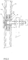
- the glass structure is made up of a set of panels, one of which is shown in the drawings under the reference 1, and it is made up of two paired and parallel glazings 2a and 2b.
- the panel is supported by a support structure 3, to which it is connected by the rod 4 ending in the ball joint 5.
- This ball joint is inserted into a housing provided inside a socket designated by the general reference 6 and constituted, in its center, by a body of generally cylindrical shape 7 from which starts radially outwards, the disc ring finger 8.
- the rod 4 carrying the ball 5 and connecting the latter to the supporting structure 3, is engaged in a channel 9 through which the central spherical housing receiving the ball 5 opens onto the interior space of the architectural volume.
- This channel has a conical shape open towards the support structure 3 arranged inside the architectural space.
- the ball joint is placed in its receiving housing and the center of the spherical ball joint is arranged in the median plane, on the one hand of the assembly of the double-glazed panel and on the other hand of the annular disc 8.
- the median plane of the annular disc 8 is arranged in an equatorial plane relative to the ball 5 and its receiving housing, this plane being perpendicular to the axis of the average position of the rod 4;
- the spherical housing receiving the ball 5 is formed on the one hand by the spherical cap 7a coming from the wall of the cylindrical body 7 opening onto said housing, and on the other hand by the hemispherical wall 10 coming from the shutter 11 engaged by screwing inside a threaded bore provided on the cylindrical body 7, the transverse face 10 of this shutter thus closing the spherical housing receiving the ball.
- the shutter 11 is itself internally drilled in its center oriented towards the outside, with respect to the internal support structure 3, by a blind threaded hole receiving a screw 12 ensuring the holding in position of the plate 13 coming in support on the outer face of the outer panel 2a.
- the annular disc 8 has on each face a first annular groove 14 disposed at the point of connection of the annular disc on the central cylindrical body 7. This groove communicates with an external outlet by at least one notch 15 arranged locally and according to a generator on the wall of the cylindrical body 7.
- This groove 14 faces a chamfered wall 16 coming from a circular recess provided on the glazing opposite.
- This groove thus defines a circular housing accessible from the outside by said notch 15 and allowing the injection on site of a bonding and sealing material, in particular based on silicone elastomer.
- sealing and adhesion sealant for glass application and known under the brand PROGLAZE.
- the injection can be carried out by means of injection devices commonly used in the building industry using glass panels.
- each disc has outwardly a second groove 17, of square profile in cross section and receiving a pad 18 consisting of a washer, also of square section, allowing engagement in said receiving groove.
- the washer 18 can advantageously be made of butyl and it thus offers a circular face allowing the soft and non-aggressive support of the glazed surface on the receiving disc.
- the socket 7 for receiving the ball joint, in the spherical housing internal to the socket, and the annular disc 8 are made of rigid material which may be a synthetic composite material or else a suitable metal alloy, preferably light such as an alloy with aluminum base.
- the panels can in fact be prepared in the factory by securing the two panes of glass on the receiving disc.
- This disc receives in the first place the butyl pad formed by a preformed washer and the O-ring on which the glazing is applied.
- the extrusion and injection through the notch of flowing silicone and filling the primary groove and the corresponding circular housing, ensure a total seal and the assembly of the assembly after rapid setting of about two hours.
- the rod 4 carrying the ball joint 5, not yet fixed to the support structure can be inserted and put in place in its housing from the outside, the shutter 11 then being in position clear. After insertion of the ball joint into its housing, this housing is closed by screwing the shutter 11, the hemispherical face of which restores the spherical capacity containing the ball joint.
- the establishment of the external screw engaged on the shutter and of the safety plate 13 then makes it possible to complete this aspect of the mounting at the level of the panel.
- the rod 4 can then be fixed to the supporting structure 3 by means of bolting members in a known manner, the adjustment of the positioning of the ball joint according to the correct plane being effected by adjusting the distance between the ball joint and the fixed structure 3.
- the assembly makes it possible to produce panels and glass surfaces of large dimensions easily installed on the site and ensuring very valuable technical advantages.
- Standard elements are used and assembly can thus be carried out quickly and automatically. We avoids protrusion of protruding organs outwards and a substantially continuous surface is produced allowing a beautiful aesthetic effect.
- FIGS. 3A and 3B show an alternative embodiment in which the shutter 11 (of FIG. 1) is associated by a screw 12 with a locking piece 25 whose upper and lower edges are bevelled and cooperate with corresponding bevelled edges of the glass panel 2a.
- the beveled blocking part 25 is itself associated with a circular plate 13, by means of the screw 12, said circular plate 13 covering the edge of the glass panel 2a.
- the circular plate 13 projects beyond the bevelled support piece 25, with respect to the axis of symmetry defined by the screw 12 and the ball joint.
Landscapes
- Engineering & Computer Science (AREA)
- Civil Engineering (AREA)
- Structural Engineering (AREA)
- Securing Of Glass Panes Or The Like (AREA)
- Joining Of Glass To Other Materials (AREA)
- Special Wing (AREA)
Applications Claiming Priority (2)
| Application Number | Priority Date | Filing Date | Title |
|---|---|---|---|
| FR9407113 | 1994-06-10 | ||
| FR9407113A FR2721090B1 (fr) | 1994-06-10 | 1994-06-10 | Perfectionnement aux dispositifs pour la fixation et le support de structures verrières. |
Publications (2)
| Publication Number | Publication Date |
|---|---|
| EP0686751A1 true EP0686751A1 (de) | 1995-12-13 |
| EP0686751B1 EP0686751B1 (de) | 1998-04-15 |
Family
ID=9464081
Family Applications (1)
| Application Number | Title | Priority Date | Filing Date |
|---|---|---|---|
| EP95401338A Expired - Lifetime EP0686751B1 (de) | 1994-06-10 | 1995-06-09 | Verbesserung an Mitteln für Befestigung und Halterung von in die Verglasung integrierte Struktur |
Country Status (4)
| Country | Link |
|---|---|
| EP (1) | EP0686751B1 (de) |
| AT (1) | ATE165137T1 (de) |
| DE (1) | DE69502054D1 (de) |
| FR (1) | FR2721090B1 (de) |
Cited By (4)
| Publication number | Priority date | Publication date | Assignee | Title |
|---|---|---|---|---|
| EP0965721A1 (de) * | 1998-06-17 | 1999-12-22 | Glas Trösch Holding AG | Befestigung für Isolierglaselement |
| US6430894B1 (en) | 1997-12-26 | 2002-08-13 | Hankuk Glass Industries Inc. | Sealed double glazing unit |
| EP1243739A1 (de) * | 2001-03-23 | 2002-09-25 | SWS Gesellschaft für Glasbaubeschläge mbH | Punkthalter für Platten |
| CN111364695A (zh) * | 2020-05-08 | 2020-07-03 | 中建八局第一建设有限公司 | 一种可有限转动的球铰式屋面玻璃系统及其安装方法 |
Families Citing this family (1)
| Publication number | Priority date | Publication date | Assignee | Title |
|---|---|---|---|---|
| DE102012202134B4 (de) * | 2012-02-13 | 2018-02-15 | HERO-FIRE GmbH | Brandschutzverbundscheibe und Herstellungsverfahren |
Citations (5)
| Publication number | Priority date | Publication date | Assignee | Title |
|---|---|---|---|---|
| EP0192472A2 (de) * | 1985-02-19 | 1986-08-27 | Pilkington Plc | Abgedichtete Doppelscheibeneinheit |
| EP0301617A1 (de) * | 1987-07-23 | 1989-02-01 | Buva Rationele Bouwprodukten Bv | Mehrscheibenverglasung |
| GB2242248A (en) * | 1990-03-21 | 1991-09-25 | Thomas Albert Summers | A structural bolt |
| EP0506522A1 (de) * | 1991-03-29 | 1992-09-30 | Saint-Gobain Vitrage | Befestigungssystem |
| FR2703092A1 (fr) * | 1993-03-25 | 1994-09-30 | Vertal Sud Est | Dispositif de fixation d'un vitrage sur une structure porteuse. |
-
1994
- 1994-06-10 FR FR9407113A patent/FR2721090B1/fr not_active Expired - Fee Related
-
1995
- 1995-06-09 AT AT95401338T patent/ATE165137T1/de not_active IP Right Cessation
- 1995-06-09 DE DE69502054T patent/DE69502054D1/de not_active Expired - Lifetime
- 1995-06-09 EP EP95401338A patent/EP0686751B1/de not_active Expired - Lifetime
Patent Citations (5)
| Publication number | Priority date | Publication date | Assignee | Title |
|---|---|---|---|---|
| EP0192472A2 (de) * | 1985-02-19 | 1986-08-27 | Pilkington Plc | Abgedichtete Doppelscheibeneinheit |
| EP0301617A1 (de) * | 1987-07-23 | 1989-02-01 | Buva Rationele Bouwprodukten Bv | Mehrscheibenverglasung |
| GB2242248A (en) * | 1990-03-21 | 1991-09-25 | Thomas Albert Summers | A structural bolt |
| EP0506522A1 (de) * | 1991-03-29 | 1992-09-30 | Saint-Gobain Vitrage | Befestigungssystem |
| FR2703092A1 (fr) * | 1993-03-25 | 1994-09-30 | Vertal Sud Est | Dispositif de fixation d'un vitrage sur une structure porteuse. |
Non-Patent Citations (1)
| Title |
|---|
| I. RITCHIE ARC.: "perfectly high-tech: British made!", DBZ, vol. 39, no. 2, February 1991 (1991-02-01), GUTERSLOH, pages 219 - 224, XP000215545 * |
Cited By (4)
| Publication number | Priority date | Publication date | Assignee | Title |
|---|---|---|---|---|
| US6430894B1 (en) | 1997-12-26 | 2002-08-13 | Hankuk Glass Industries Inc. | Sealed double glazing unit |
| EP0965721A1 (de) * | 1998-06-17 | 1999-12-22 | Glas Trösch Holding AG | Befestigung für Isolierglaselement |
| EP1243739A1 (de) * | 2001-03-23 | 2002-09-25 | SWS Gesellschaft für Glasbaubeschläge mbH | Punkthalter für Platten |
| CN111364695A (zh) * | 2020-05-08 | 2020-07-03 | 中建八局第一建设有限公司 | 一种可有限转动的球铰式屋面玻璃系统及其安装方法 |
Also Published As
| Publication number | Publication date |
|---|---|
| FR2721090A1 (fr) | 1995-12-15 |
| ATE165137T1 (de) | 1998-05-15 |
| DE69502054D1 (de) | 1998-05-20 |
| EP0686751B1 (de) | 1998-04-15 |
| FR2721090B1 (fr) | 1996-07-26 |
Similar Documents
| Publication | Publication Date | Title |
|---|---|---|
| EP0655543B1 (de) | Mechanische Verbindung zwischen einer Glasscheibe und einer Tragestruktur | |
| EP0506522B1 (de) | Befestigungssystem | |
| FR2986598A1 (fr) | Joint d'etancheite | |
| EP2739885B1 (de) | Dichtung | |
| EP0686751B1 (de) | Verbesserung an Mitteln für Befestigung und Halterung von in die Verglasung integrierte Struktur | |
| EP0552101A1 (de) | Isolierverglasung | |
| FR2890096A1 (fr) | Porte isolante | |
| EP3896535A1 (de) | Abdichtungssystem für uhrengehäuse | |
| FR3027620A1 (fr) | Fenetre ou porte en particulier bloc fenetre | |
| FR2656390A1 (fr) | Dispositif de liaison entre deux profiles. | |
| FR2493958A3 (fr) | Luminaire etanche a la poussiere et protege contre les jets d'eau | |
| FR2745028A1 (fr) | Procede de realisation d'un joint espaceur pour vitrage colle | |
| BE1019123A3 (fr) | Systeme de fixation, isolant, d'un vitrage sur une structure porteuse. | |
| EP0297952B1 (de) | Befestigungsvorrichtung einer Platte, insbesondere einer Glasscheibe auf einem Tragrahmen | |
| EP1114909B1 (de) | Verfahren und Bausatz zur Befestigung von Tafeln mit doppelten Flanken | |
| FR2652609A1 (fr) | Dispositif de fixation d'un panneau a double vitrage. | |
| EP0859112B1 (de) | Fenster oder Tür mit einer dünnen Hochleistungsisolierverglasung | |
| EP1083289A1 (de) | Mechanische Verbindungsvorrichtung in einem Befestigungssystem von Elementen an einer Tragstuktur | |
| FR2575427A1 (fr) | Dispositif pour realiser une fixation etanche d'un organe sur une paroi, notamment une tole de carrosserie automobile et appplication d'un tel dispositif a la fixation d'accessoires automobiles, en particulier a la fixation d'une embase d'antenne | |
| FR2741095A1 (fr) | Dispositif d'etancheite entre cadres d'une ossature pour facade du type mur-rideau | |
| FR2736381A1 (fr) | Garniture d'etancheite et de protection pour porte, fenetre ou analogue | |
| FR2816340A1 (fr) | Dispositif d'assemblage de profiles de structure de toiture, en particulier de verriere, a multiple degres de liberte de position | |
| FR2740817A1 (fr) | Piece d'angle pour chassis d'ouvrant de porte ou fenetre | |
| FR3155744A1 (fr) | Vitrage comportant un systeme d’eclairage interieur, systeme d’eclairage interieur et procede de fabrication d’un tel vitrage | |
| LU85600A1 (fr) | Profile d'adaptation pour vitrages multiples |
Legal Events
| Date | Code | Title | Description |
|---|---|---|---|
| PUAI | Public reference made under article 153(3) epc to a published international application that has entered the european phase |
Free format text: ORIGINAL CODE: 0009012 |
|
| AK | Designated contracting states |
Kind code of ref document: A1 Designated state(s): AT BE CH DE DK ES FR GB LI LU NL SE |
|
| 17P | Request for examination filed |
Effective date: 19960328 |
|
| GRAG | Despatch of communication of intention to grant |
Free format text: ORIGINAL CODE: EPIDOS AGRA |
|
| 17Q | First examination report despatched |
Effective date: 19970807 |
|
| GRAG | Despatch of communication of intention to grant |
Free format text: ORIGINAL CODE: EPIDOS AGRA |
|
| GRAH | Despatch of communication of intention to grant a patent |
Free format text: ORIGINAL CODE: EPIDOS IGRA |
|
| GRAH | Despatch of communication of intention to grant a patent |
Free format text: ORIGINAL CODE: EPIDOS IGRA |
|
| GRAA | (expected) grant |
Free format text: ORIGINAL CODE: 0009210 |
|
| AK | Designated contracting states |
Kind code of ref document: B1 Designated state(s): AT BE CH DE DK ES FR GB LI LU NL SE |
|
| PG25 | Lapsed in a contracting state [announced via postgrant information from national office to epo] |
Ref country code: NL Free format text: LAPSE BECAUSE OF FAILURE TO SUBMIT A TRANSLATION OF THE DESCRIPTION OR TO PAY THE FEE WITHIN THE PRESCRIBED TIME-LIMIT Effective date: 19980415 Ref country code: GB Free format text: LAPSE BECAUSE OF FAILURE TO SUBMIT A TRANSLATION OF THE DESCRIPTION OR TO PAY THE FEE WITHIN THE PRESCRIBED TIME-LIMIT Effective date: 19980415 Ref country code: ES Free format text: THE PATENT HAS BEEN ANNULLED BY A DECISION OF A NATIONAL AUTHORITY Effective date: 19980415 Ref country code: AT Free format text: LAPSE BECAUSE OF FAILURE TO SUBMIT A TRANSLATION OF THE DESCRIPTION OR TO PAY THE FEE WITHIN THE PRESCRIBED TIME-LIMIT Effective date: 19980415 |
|
| REF | Corresponds to: |
Ref document number: 165137 Country of ref document: AT Date of ref document: 19980515 Kind code of ref document: T |
|
| REG | Reference to a national code |
Ref country code: CH Ref legal event code: EP |
|
| REF | Corresponds to: |
Ref document number: 69502054 Country of ref document: DE Date of ref document: 19980520 |
|
| PG25 | Lapsed in a contracting state [announced via postgrant information from national office to epo] |
Ref country code: LU Free format text: LAPSE BECAUSE OF NON-PAYMENT OF DUE FEES Effective date: 19980609 |
|
| PG25 | Lapsed in a contracting state [announced via postgrant information from national office to epo] |
Ref country code: SE Free format text: LAPSE BECAUSE OF FAILURE TO SUBMIT A TRANSLATION OF THE DESCRIPTION OR TO PAY THE FEE WITHIN THE PRESCRIBED TIME-LIMIT Effective date: 19980715 Ref country code: DK Free format text: LAPSE BECAUSE OF FAILURE TO SUBMIT A TRANSLATION OF THE DESCRIPTION OR TO PAY THE FEE WITHIN THE PRESCRIBED TIME-LIMIT Effective date: 19980715 |
|
| PG25 | Lapsed in a contracting state [announced via postgrant information from national office to epo] |
Ref country code: DE Free format text: LAPSE BECAUSE OF FAILURE TO SUBMIT A TRANSLATION OF THE DESCRIPTION OR TO PAY THE FEE WITHIN THE PRESCRIBED TIME-LIMIT Effective date: 19980716 |
|
| NLV1 | Nl: lapsed or annulled due to failure to fulfill the requirements of art. 29p and 29m of the patents act | ||
| GBV | Gb: ep patent (uk) treated as always having been void in accordance with gb section 77(7)/1977 [no translation filed] |
Effective date: 19980415 |
|
| PLBE | No opposition filed within time limit |
Free format text: ORIGINAL CODE: 0009261 |
|
| STAA | Information on the status of an ep patent application or granted ep patent |
Free format text: STATUS: NO OPPOSITION FILED WITHIN TIME LIMIT |
|
| 26N | No opposition filed | ||
| PG25 | Lapsed in a contracting state [announced via postgrant information from national office to epo] |
Ref country code: LI Free format text: LAPSE BECAUSE OF NON-PAYMENT OF DUE FEES Effective date: 19990630 Ref country code: CH Free format text: LAPSE BECAUSE OF NON-PAYMENT OF DUE FEES Effective date: 19990630 |
|
| REG | Reference to a national code |
Ref country code: CH Ref legal event code: PL |
|
| REG | Reference to a national code |
Ref country code: FR Ref legal event code: ST |
|
| REG | Reference to a national code |
Ref country code: FR Ref legal event code: RN |
|
| REG | Reference to a national code |
Ref country code: FR Ref legal event code: FC |
|
| PGFP | Annual fee paid to national office [announced via postgrant information from national office to epo] |
Ref country code: FR Payment date: 20060630 Year of fee payment: 12 |
|
| PGFP | Annual fee paid to national office [announced via postgrant information from national office to epo] |
Ref country code: BE Payment date: 20060711 Year of fee payment: 12 |
|
| BERE | Be: lapsed |
Owner name: S.A. *LAUBEUF Effective date: 20070630 |
|
| PG25 | Lapsed in a contracting state [announced via postgrant information from national office to epo] |
Ref country code: BE Free format text: LAPSE BECAUSE OF NON-PAYMENT OF DUE FEES Effective date: 20070630 |
|
| REG | Reference to a national code |
Ref country code: FR Ref legal event code: ST Effective date: 20080229 |
|
| PG25 | Lapsed in a contracting state [announced via postgrant information from national office to epo] |
Ref country code: FR Free format text: LAPSE BECAUSE OF NON-PAYMENT OF DUE FEES Effective date: 20070702 |