EP0686771A2 - Pompe à engrenages internes avec joint d'étanchéité incorporé dans les dents - Google Patents
Pompe à engrenages internes avec joint d'étanchéité incorporé dans les dents Download PDFInfo
- Publication number
- EP0686771A2 EP0686771A2 EP95107368A EP95107368A EP0686771A2 EP 0686771 A2 EP0686771 A2 EP 0686771A2 EP 95107368 A EP95107368 A EP 95107368A EP 95107368 A EP95107368 A EP 95107368A EP 0686771 A2 EP0686771 A2 EP 0686771A2
- Authority
- EP
- European Patent Office
- Prior art keywords
- internal gear
- ring gear
- pinion
- gear pump
- control
- Prior art date
- Legal status (The legal status is an assumption and is not a legal conclusion. Google has not performed a legal analysis and makes no representation as to the accuracy of the status listed.)
- Granted
Links
Images

Classifications
-
- F—MECHANICAL ENGINEERING; LIGHTING; HEATING; WEAPONS; BLASTING
- F04—POSITIVE - DISPLACEMENT MACHINES FOR LIQUIDS; PUMPS FOR LIQUIDS OR ELASTIC FLUIDS
- F04C—ROTARY-PISTON, OR OSCILLATING-PISTON, POSITIVE-DISPLACEMENT MACHINES FOR LIQUIDS; ROTARY-PISTON, OR OSCILLATING-PISTON, POSITIVE-DISPLACEMENT PUMPS
- F04C2/00—Rotary-piston machines or pumps
- F04C2/08—Rotary-piston machines or pumps of intermeshing-engagement type, i.e. with engagement of co-operating members similar to that of toothed gearing
- F04C2/10—Rotary-piston machines or pumps of intermeshing-engagement type, i.e. with engagement of co-operating members similar to that of toothed gearing of internal-axis type with the outer member having more teeth or tooth-equivalents, e.g. rollers, than the inner member
- F04C2/102—Rotary-piston machines or pumps of intermeshing-engagement type, i.e. with engagement of co-operating members similar to that of toothed gearing of internal-axis type with the outer member having more teeth or tooth-equivalents, e.g. rollers, than the inner member the two members rotating simultaneously around their respective axes
-
- F—MECHANICAL ENGINEERING; LIGHTING; HEATING; WEAPONS; BLASTING
- F04—POSITIVE - DISPLACEMENT MACHINES FOR LIQUIDS; PUMPS FOR LIQUIDS OR ELASTIC FLUIDS
- F04C—ROTARY-PISTON, OR OSCILLATING-PISTON, POSITIVE-DISPLACEMENT MACHINES FOR LIQUIDS; ROTARY-PISTON, OR OSCILLATING-PISTON, POSITIVE-DISPLACEMENT PUMPS
- F04C15/00—Component parts, details or accessories of machines, pumps or pumping installations, not provided for in groups F04C2/00 - F04C14/00
- F04C15/0003—Sealing arrangements in rotary-piston machines or pumps
- F04C15/0007—Radial sealings for working fluid
- F04C15/0019—Radial sealing elements specially adapted for intermeshing-engagement type machines or pumps, e.g. gear machines or pumps
Definitions
- the present invention relates to a sickle-free internal gear pump with sealing elements inserted into the tooth heads and driven on the back via pressure channels according to the preamble of claim 1.
- a pump of the generic type is known as a special embodiment from DE 41 40 293 A1, which in turn is based on a prior art according to DE 41 04 397 A1.
- P 43 01 104.7 in view of the inventions mentioned, in connection with the optimization of the pressure build-up between the opposing tooth tips of the ring gear and pinion, a back pressure application of the sealing (or radial) elements was already proposed.
- the constructive implementation of this proposal is based on the fact that the sealing element has a plurality of bores or a lateral groove, via which the back of the sealing element is subjected to a partial pressure of the working pressure.
- the object on which the present invention is based is to provide a simpler and therefore less expensive solution for pressurizing the radial elements on the rear side.
- At least one axial control slot is incorporated on at least one side of the part of the housing which laterally delimits the ring gear and the pinion.
- the essence of the present invention is to no longer incorporate the "control grooves" for relieving the contact pressure of the radial element in the pressure build-up zone into the radial elements themselves, but rather in the spatial area of the pressure build-up zone in the rotating toothed parts (ring gear and pinion) adjacent area of the housing to verify machined axial grooves or slots.
- the "control chamber" in the ring gear is on the one hand with the leading and on the other hand with the trailing over a larger effective area relative to the control chamber width by two groups of axial grooves machined parallel to one another in the housing Tooth gap connected, without a (communicating) connection between the adjacent tooth gaps.
- the hydraulic pressure in the "control chamber” is controlled by an axial control slot in the housing, which temporarily connects two tooth gaps to one another and which, through its cross-sectional shape which is variable via the angle of rotation, enables any pressure setting in the control chamber.
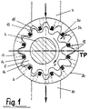
- FIG. 1 shows in a cross section a sickle-free, head-sealing and play-afflicted internal gear pump, each with a flank sealing, in the area of a housing middle part, which - viewed in the axial direction - is followed by further housing parts.
- An externally toothed pinion 5 fastened on a pinion shaft 4 is in engagement with an internally toothed ring gear 6.
- the toothing 12 of the pinion 5 and the ring gear 6 has an axial width which is greater than the pitch circle diameter of the pinion 5.
- This pinion 5 and the ring gear 6 are not coaxial, but eccentric to each other; furthermore, the pinion 5 has one tooth less than the ring gear 6, so that in each case the outside of a tooth head 13 on the pinion 5 comes into contact with the inside of a tooth head 14 on the ring gear 6.
- a suction connection 7 can also be seen in the zone in which the teeth on the pinion 5 or on the ring gear 6 disengage when rotated in the direction of the arrow X.
- the suction port 7 in the middle part of the housing, in which the ring gear 6 and the pinion 5 are mounted, is followed in the axial direction by a suction pocket which adjoins the adjacent housing part extends part of the outer surface 20 of the ring gear 6.
- a pressure connection 10 is located, likewise starting from a pressure pocket extending over a circumferential area on the ring gear 6, on the opposite side of the pump.
- radially movable (arrow Y), preferably mushroom-shaped sealing elements 30 are used on the tooth heads of the ring gear 6 in a manner known per se, but in no way restrictive, which are in a complementary profile groove 34 stored or held.
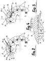
- FIGS. 2 and 3 show a section of the internal gear pump shown in FIG. 1 and explained above, specifically in the region of the pressure build-up zone Z adjoining the so-called dead center TP of the pump.
- the representations according to FIGS. 2 and 3 are clear it can be seen how the functional separation of the suction and pressure chamber of the internal gear pump takes place via the relative movement between the ring gear 6 and the pinion 5 and via the sealing elements 30.
- the subject of the present invention is the control of the so-called control spaces 35 of the sealing elements 30, ie the free space on the rear between the underside of the sealing elements 30 and the base of the profile grooves 34 Activation takes place via axial grooves incorporated into the housing 19 (see FIG. 4) which laterally delimit the toothing parts (ring gear 6 and pinion 5) - namely via a plurality of grooves 40 which are incorporated obliquely in the area of the dead center TP with a negative angle of attack are (Fig. 2) and a (second) plurality of grooves 41, which are incorporated obliquely with a positive angle of attack, viewed in the direction of rotation X, behind the dead center TP (Fig. 3).
- the control chamber 35 of the sealing element 30 that exceeds the dead center TP now always has the same pressure as that of the controlled tooth gap.
- FIG. 4 shows a sectional view corresponding to the section line A-B according to FIG. 3, on the one hand to show the arrangement of the grooves 41 in the housing 19 and on the other hand their shape as, for example, rectangular milling.
- a communicating connection between the control chamber 35 of the leading sealing element (30.v in FIG. 3) and the trailing tooth gap 16.n is opened in succession via the grooves 41.
- the control slot 45 viewed in the circumferential direction, can be curved (see illustration) or run straight; With regard to its cross-sectional shape, the control slot 45 can be designed variably, so that the partial pressure acting in the control chamber 35 can be optimized via the cross-sections effective depending on the angular position (compare I and II).
- the above-mentioned geometric relationships are also shown enlarged with reference to FIG. 7 along the section line C-D according to FIG. 6.
- the control slot 45 in the housing 19 connects the adjacent tooth gaps 16.x and 16.y and initiates a partial pressure corresponding to the cross sections I and II in the control chamber 35 of the conjugated sealing element 30.
- FIGS. 2/3/4 on the one hand and FIGS. 5/6/7 on the other hand are each suitable for solving the object on which the present invention is based.
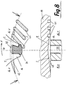
- This configuration is shown in FIG. 8 in two views, partially in section.
- control chamber 35 formed in the tooth head 14 of the ring gear 6 at the base of the sealing element 30 is pressurized once via a control slot 45 machined in the circumferential direction analogously to the exemplary embodiment described with reference to FIGS. 5/6/7; on the other hand, the control chamber 35 is also connected to the trailing tooth space 16.n via the (here three) grooves 41.
- the latter grooves 41 also have a rectangular cross-sectional shape, for example.
- the control slot 45 is bent along the circumferential line of the control spaces 35 and is formed over its entire length as a conical fillet groove tapering on both sides.
Landscapes
- Engineering & Computer Science (AREA)
- Mechanical Engineering (AREA)
- General Engineering & Computer Science (AREA)
- Rotary Pumps (AREA)
- Details And Applications Of Rotary Liquid Pumps (AREA)
Applications Claiming Priority (2)
| Application Number | Priority Date | Filing Date | Title |
|---|---|---|---|
| DE4419975 | 1994-06-08 | ||
| DE4419975A DE4419975A1 (de) | 1994-06-08 | 1994-06-08 | Sichellose Innenzahnradpumpe mit in die Zahnköpfe eingesetzten, rückseitig über Druckkanäle angesteuerten Dichtelementen |
Publications (3)
| Publication Number | Publication Date |
|---|---|
| EP0686771A2 true EP0686771A2 (fr) | 1995-12-13 |
| EP0686771A3 EP0686771A3 (fr) | 1996-08-14 |
| EP0686771B1 EP0686771B1 (fr) | 1999-07-28 |
Family
ID=6520060
Family Applications (1)
| Application Number | Title | Priority Date | Filing Date |
|---|---|---|---|
| EP95107368A Expired - Lifetime EP0686771B1 (fr) | 1994-06-08 | 1995-05-16 | Pompe à engrenages internes avec joint d'étanchéité incorporé dans les dents |
Country Status (8)
| Country | Link |
|---|---|
| US (1) | US5582514A (fr) |
| EP (1) | EP0686771B1 (fr) |
| JP (1) | JPH0842460A (fr) |
| KR (1) | KR960001491A (fr) |
| AT (1) | ATE182660T1 (fr) |
| DE (2) | DE4419975A1 (fr) |
| DK (1) | DK0686771T3 (fr) |
| ES (1) | ES2135626T3 (fr) |
Cited By (1)
| Publication number | Priority date | Publication date | Assignee | Title |
|---|---|---|---|---|
| EP0911524A1 (fr) * | 1997-10-23 | 1999-04-28 | Robert Bosch Gmbh | Pompe à engrenages internes |
Families Citing this family (3)
| Publication number | Priority date | Publication date | Assignee | Title |
|---|---|---|---|---|
| US6106256A (en) * | 1998-04-20 | 2000-08-22 | Walbro Corporation | Gear rotor fuel pump |
| US6273695B1 (en) * | 1999-03-26 | 2001-08-14 | Voith Turbo Gmbh & Co. Kg | Sickleless internal gear wheel pump with sealing elements inserted into the tooth tips |
| CN104895781A (zh) * | 2014-09-17 | 2015-09-09 | 襄阳博亚精工装备股份有限公司 | 一种内啮合齿轮泵 |
Family Cites Families (8)
| Publication number | Priority date | Publication date | Assignee | Title |
|---|---|---|---|---|
| US2866417A (en) * | 1956-06-11 | 1958-12-30 | Hanomag Ag | Rotary piston machine |
| US3680989A (en) * | 1970-09-21 | 1972-08-01 | Emerson Electric Co | Hydraulic pump or motor |
| JPS61138893A (ja) * | 1984-12-07 | 1986-06-26 | Aisin Seiki Co Ltd | トロコイド型オイルポンプ |
| DE4104397C2 (de) * | 1990-03-09 | 1993-12-16 | Voith Gmbh J M | Innenzahnradpumpe |
| JPH0579466A (ja) * | 1991-09-18 | 1993-03-30 | Toyooki Kogyo Co Ltd | 内接型ギアポンプ |
| DE4140293C2 (de) * | 1991-12-06 | 1994-06-01 | Voith Gmbh J M | Sichellose Innenzahnradpumpe mit in die Zahnköpfe eingesetzten Dichtelementen |
| JP2657963B2 (ja) * | 1992-12-18 | 1997-09-30 | 株式会社ポリマーシステムズ | 充填装置 |
| ATE139305T1 (de) * | 1993-01-18 | 1996-06-15 | Voith Gmbh J M | Sichellose innenzahnradpumpe mit in die zahnköpfe eingesetzten dichtelementen |
-
1994
- 1994-06-08 DE DE4419975A patent/DE4419975A1/de not_active Withdrawn
-
1995
- 1995-05-16 EP EP95107368A patent/EP0686771B1/fr not_active Expired - Lifetime
- 1995-05-16 DK DK95107368T patent/DK0686771T3/da active
- 1995-05-16 AT AT95107368T patent/ATE182660T1/de not_active IP Right Cessation
- 1995-05-16 DE DE59506453T patent/DE59506453D1/de not_active Expired - Lifetime
- 1995-05-16 ES ES95107368T patent/ES2135626T3/es not_active Expired - Lifetime
- 1995-06-03 KR KR1019950014703A patent/KR960001491A/ko not_active Withdrawn
- 1995-06-07 US US08/477,678 patent/US5582514A/en not_active Expired - Lifetime
- 1995-06-08 JP JP7141818A patent/JPH0842460A/ja active Pending
Cited By (1)
| Publication number | Priority date | Publication date | Assignee | Title |
|---|---|---|---|---|
| EP0911524A1 (fr) * | 1997-10-23 | 1999-04-28 | Robert Bosch Gmbh | Pompe à engrenages internes |
Also Published As
| Publication number | Publication date |
|---|---|
| EP0686771A3 (fr) | 1996-08-14 |
| US5582514A (en) | 1996-12-10 |
| DE59506453D1 (de) | 1999-09-02 |
| DK0686771T3 (da) | 2000-02-28 |
| JPH0842460A (ja) | 1996-02-13 |
| ES2135626T3 (es) | 1999-11-01 |
| KR960001491A (ko) | 1996-01-25 |
| EP0686771B1 (fr) | 1999-07-28 |
| ATE182660T1 (de) | 1999-08-15 |
| DE4419975A1 (de) | 1995-12-14 |
Similar Documents
| Publication | Publication Date | Title |
|---|---|---|
| DE29703656U1 (de) | Füllstücklose Innenzahnradpumpe | |
| DE2818332A1 (de) | Verfahren zur herstellung einer antriebswelle mit balligen aussenkeilzaehnen | |
| DE19834843A1 (de) | Einrichtung zur relativen Drehlagenänderung einer Welle zum Antriebsrad | |
| DE4104397C2 (de) | Innenzahnradpumpe | |
| DE2225757B2 (de) | Gelenk für eine verstellbare Rückenlehne eines Sitzes | |
| DE4143466C2 (de) | Steuerscheibe für Flügelzellenpumpe | |
| AT520015A1 (de) | Baugruppe mit einer Steckverzahnung | |
| EP0686771A2 (fr) | Pompe à engrenages internes avec joint d'étanchéité incorporé dans les dents | |
| DE10052779A1 (de) | Füllstücklose Innenzahnradpumpe | |
| DE3710817A1 (de) | Drehkolbenmaschine, insbesondere zahnringmaschine | |
| DE2921311C2 (fr) | ||
| DE102008046821A1 (de) | Kurbelwelle für eine Brennkraftmaschine mit varibaler Verdichtung und Brennkraftmaschine mit variabler Verdichtung | |
| EP0539673B1 (fr) | Pompe à engrenage interne avec deux couronnes et un pignon commun | |
| DE4109149C2 (de) | Steuerscheibe für Flügelzellenpumpe | |
| DE102005047175A1 (de) | Flügelzellenpumpe | |
| DE3428757A1 (de) | Drehschieberventil | |
| DE19723608C2 (de) | Falzapparat für Klappenfalz | |
| EP0607497A1 (fr) | Pompe à engrenages internes avec joint d'étanchéité incorporé dans les dents | |
| EP2655802B1 (fr) | Machine à engrenage à rapport diamètre-longueur réduit | |
| WO2012084289A2 (fr) | Pompe, compresseur ou moteur | |
| EP0866225B1 (fr) | Pompe à engrenages internes avec de segments d'étanchéité inserés dans les têtes des dents | |
| EP3540266B1 (fr) | Roue dentée ainsi qu'un élément denté pour une transmission à éléments dentés ainsi que transmission à éléments dentés correspondante | |
| DE2142323A1 (de) | Flüssigkeitstrieb | |
| DE102016213696B4 (de) | Zahnradfluidmaschine | |
| DE102015201468A1 (de) | Planetenstufe für ein Getriebe |
Legal Events
| Date | Code | Title | Description |
|---|---|---|---|
| PUAI | Public reference made under article 153(3) epc to a published international application that has entered the european phase |
Free format text: ORIGINAL CODE: 0009012 |
|
| AK | Designated contracting states |
Kind code of ref document: A2 Designated state(s): AT BE CH DE DK ES FR GB IT LI NL SE |
|
| PUAL | Search report despatched |
Free format text: ORIGINAL CODE: 0009013 |
|
| AK | Designated contracting states |
Kind code of ref document: A3 Designated state(s): AT BE CH DE DK ES FR GB IT LI NL SE |
|
| 17P | Request for examination filed |
Effective date: 19961203 |
|
| GRAG | Despatch of communication of intention to grant |
Free format text: ORIGINAL CODE: EPIDOS AGRA |
|
| 17Q | First examination report despatched |
Effective date: 19980728 |
|
| GRAG | Despatch of communication of intention to grant |
Free format text: ORIGINAL CODE: EPIDOS AGRA |
|
| GRAH | Despatch of communication of intention to grant a patent |
Free format text: ORIGINAL CODE: EPIDOS IGRA |
|
| RAP1 | Party data changed (applicant data changed or rights of an application transferred) |
Owner name: J.M. VOITH GMBH & CO. BETEILIGUNGEN KG |
|
| GRAH | Despatch of communication of intention to grant a patent |
Free format text: ORIGINAL CODE: EPIDOS IGRA |
|
| GRAA | (expected) grant |
Free format text: ORIGINAL CODE: 0009210 |
|
| AK | Designated contracting states |
Kind code of ref document: B1 Designated state(s): AT BE CH DE DK ES FR GB IT LI NL SE |
|
| REF | Corresponds to: |
Ref document number: 182660 Country of ref document: AT Date of ref document: 19990815 Kind code of ref document: T |
|
| REG | Reference to a national code |
Ref country code: CH Ref legal event code: EP |
|
| GBT | Gb: translation of ep patent filed (gb section 77(6)(a)/1977) |
Effective date: 19990729 |
|
| REF | Corresponds to: |
Ref document number: 59506453 Country of ref document: DE Date of ref document: 19990902 |
|
| ITF | It: translation for a ep patent filed | ||
| REG | Reference to a national code |
Ref country code: ES Ref legal event code: FG2A Ref document number: 2135626 Country of ref document: ES Kind code of ref document: T3 |
|
| ET | Fr: translation filed | ||
| REG | Reference to a national code |
Ref country code: DK Ref legal event code: T3 |
|
| PG25 | Lapsed in a contracting state [announced via postgrant information from national office to epo] |
Ref country code: AT Free format text: LAPSE BECAUSE OF NON-PAYMENT OF DUE FEES Effective date: 20000516 |
|
| PLBE | No opposition filed within time limit |
Free format text: ORIGINAL CODE: 0009261 |
|
| STAA | Information on the status of an ep patent application or granted ep patent |
Free format text: STATUS: NO OPPOSITION FILED WITHIN TIME LIMIT |
|
| PG25 | Lapsed in a contracting state [announced via postgrant information from national office to epo] |
Ref country code: LI Free format text: LAPSE BECAUSE OF NON-PAYMENT OF DUE FEES Effective date: 20000531 Ref country code: CH Free format text: LAPSE BECAUSE OF NON-PAYMENT OF DUE FEES Effective date: 20000531 |
|
| 26N | No opposition filed | ||
| REG | Reference to a national code |
Ref country code: CH Ref legal event code: PL |
|
| REG | Reference to a national code |
Ref country code: GB Ref legal event code: IF02 |
|
| PGFP | Annual fee paid to national office [announced via postgrant information from national office to epo] |
Ref country code: ES Payment date: 20080522 Year of fee payment: 14 Ref country code: DK Payment date: 20080526 Year of fee payment: 14 |
|
| PGFP | Annual fee paid to national office [announced via postgrant information from national office to epo] |
Ref country code: BE Payment date: 20080526 Year of fee payment: 14 Ref country code: IT Payment date: 20080520 Year of fee payment: 14 |
|
| PGFP | Annual fee paid to national office [announced via postgrant information from national office to epo] |
Ref country code: SE Payment date: 20080521 Year of fee payment: 14 Ref country code: NL Payment date: 20080528 Year of fee payment: 14 |
|
| PGFP | Annual fee paid to national office [announced via postgrant information from national office to epo] |
Ref country code: FR Payment date: 20080521 Year of fee payment: 14 |
|
| PGFP | Annual fee paid to national office [announced via postgrant information from national office to epo] |
Ref country code: GB Payment date: 20080520 Year of fee payment: 14 |
|
| BERE | Be: lapsed |
Owner name: J.M. *VOITH G.M.B.H. & CO. BETEILIGUNGEN K.G. Effective date: 20090531 |
|
| REG | Reference to a national code |
Ref country code: DK Ref legal event code: EBP |
|
| GBPC | Gb: european patent ceased through non-payment of renewal fee |
Effective date: 20090516 |
|
| NLV4 | Nl: lapsed or anulled due to non-payment of the annual fee |
Effective date: 20091201 |
|
| PG25 | Lapsed in a contracting state [announced via postgrant information from national office to epo] |
Ref country code: NL Free format text: LAPSE BECAUSE OF NON-PAYMENT OF DUE FEES Effective date: 20091201 |
|
| REG | Reference to a national code |
Ref country code: FR Ref legal event code: ST Effective date: 20100129 |
|
| PG25 | Lapsed in a contracting state [announced via postgrant information from national office to epo] |
Ref country code: FR Free format text: LAPSE BECAUSE OF NON-PAYMENT OF DUE FEES Effective date: 20090602 Ref country code: DK Free format text: LAPSE BECAUSE OF NON-PAYMENT OF DUE FEES Effective date: 20090531 |
|
| PG25 | Lapsed in a contracting state [announced via postgrant information from national office to epo] |
Ref country code: GB Free format text: LAPSE BECAUSE OF NON-PAYMENT OF DUE FEES Effective date: 20090516 |
|
| PG25 | Lapsed in a contracting state [announced via postgrant information from national office to epo] |
Ref country code: BE Free format text: LAPSE BECAUSE OF NON-PAYMENT OF DUE FEES Effective date: 20090531 |
|
| REG | Reference to a national code |
Ref country code: ES Ref legal event code: FD2A Effective date: 20090518 |
|
| PG25 | Lapsed in a contracting state [announced via postgrant information from national office to epo] |
Ref country code: ES Free format text: LAPSE BECAUSE OF NON-PAYMENT OF DUE FEES Effective date: 20090518 |
|
| PG25 | Lapsed in a contracting state [announced via postgrant information from national office to epo] |
Ref country code: IT Free format text: LAPSE BECAUSE OF NON-PAYMENT OF DUE FEES Effective date: 20090516 |
|
| PG25 | Lapsed in a contracting state [announced via postgrant information from national office to epo] |
Ref country code: SE Free format text: LAPSE BECAUSE OF NON-PAYMENT OF DUE FEES Effective date: 20090517 |
|
| PGFP | Annual fee paid to national office [announced via postgrant information from national office to epo] |
Ref country code: DE Payment date: 20110601 Year of fee payment: 17 |
|
| REG | Reference to a national code |
Ref country code: DE Ref legal event code: R119 Ref document number: 59506453 Country of ref document: DE Effective date: 20121201 |
|
| PG25 | Lapsed in a contracting state [announced via postgrant information from national office to epo] |
Ref country code: DE Free format text: LAPSE BECAUSE OF NON-PAYMENT OF DUE FEES Effective date: 20121201 |