EP0686775B1 - Dispositif de vanne électropneumatique - Google Patents
Dispositif de vanne électropneumatique Download PDFInfo
- Publication number
- EP0686775B1 EP0686775B1 EP95106525A EP95106525A EP0686775B1 EP 0686775 B1 EP0686775 B1 EP 0686775B1 EP 95106525 A EP95106525 A EP 95106525A EP 95106525 A EP95106525 A EP 95106525A EP 0686775 B1 EP0686775 B1 EP 0686775B1
- Authority
- EP
- European Patent Office
- Prior art keywords
- valve device
- valve
- pilot
- connections
- valves
- Prior art date
- Legal status (The legal status is an assumption and is not a legal conclusion. Google has not performed a legal analysis and makes no representation as to the accuracy of the status listed.)
- Expired - Lifetime
Links
Images

Classifications
-
- F—MECHANICAL ENGINEERING; LIGHTING; HEATING; WEAPONS; BLASTING
- F15—FLUID-PRESSURE ACTUATORS; HYDRAULICS OR PNEUMATICS IN GENERAL
- F15B—SYSTEMS ACTING BY MEANS OF FLUIDS IN GENERAL; FLUID-PRESSURE ACTUATORS, e.g. SERVOMOTORS; DETAILS OF FLUID-PRESSURE SYSTEMS, NOT OTHERWISE PROVIDED FOR
- F15B13/00—Details of servomotor systems ; Valves for servomotor systems
- F15B13/02—Fluid distribution or supply devices characterised by their adaptation to the control of servomotors
- F15B13/04—Fluid distribution or supply devices characterised by their adaptation to the control of servomotors for use with a single servomotor
- F15B13/0401—Valve members; Fluid interconnections therefor
- F15B13/0402—Valve members; Fluid interconnections therefor for linearly sliding valves, e.g. spool valves
Definitions
- the invention is based on an electropneumatic Valve device for independent control of two. Consumer connections according to the preamble of the claim 1 specified genus.
- DE 40 20 024 A1 is electromagnetic Actuated directional valve known as the 5/2 valve is carried out in which both are used for pilot control Solenoid valves on a single face of the actual Directional control valve are arranged.
- This is how it comes Directional control valve without adapter plate with a single one electrical connector; however, between that actual housing and the pilot valves one Intermediate plate required, which a variety of Control channels has.
- the drive pistons for the main control spool directly in the directional control valve housing performed, which causes a complex design.
- this 5/2-way valve is only for one only control function designed as for control a double-acting consumer is required. In many In this way, an optimal design is not possible for applications, especially in valve carrier systems.
- EP 0 139 259 B1 is an electrohydraulic one Control valve known in the coaxial in a housing to each other two electromagnetically operated, pre-controlled, 3/2 valves are installed. Both 3/2 valves are equal to each other and in a complex Seat valve design, so that a total of four Switching combinations are possible and the connected one double-acting motor not only moves in both directions can be, but also in a locked position and a Floating position can be brought. This valve is too executed so that it is only for a control function Control of a double-acting consumer is suitable. In the the hydraulic valve design used is suitable not for pneumatic valve carrier systems.
- the electropneumatic valve device according to the invention for independent control of two consumer connections with has the characteristic features of the main claim on the other hand the advantage that with simple and cost-effective design better with a given installation space Control functions can be used.
- This allows in valve carrier systems at a valve position use different valve series together, whereby especially two 3/2-way valves can be easily accommodated can.
- By integrating both directional valves in one Standard housings can handle higher flow rates realize, as is usually the case with a 5/2-way valve the case is.
- a separate, the consumer connections having connection plate can now be omitted. As well an adapter plate is no longer required, which means that no only space and costs decrease, but also assembly simplified and the susceptibility to interference is reduced.
- Valve setup is easy for different functions can be equipped by using the corresponding longitudinal slide differently arranged control edges are used, so that functions such as normally open, normally closed or implement combinations of these.
- the most Standard housing with flanged pilot control housing integrated pilot valves and electrical connection favors a cost-saving and compact design.
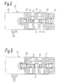
- FIG. 1 shows a partial longitudinal section by an electro-pneumatic valve device for independent control of two consumer connections in simplified representation and Figures 2 and 3 a second or third embodiment of the electropneumatic Valve device with other longitudinal slides for different functional variants.
- FIG. 1 is a simplified representation electropneumatic valve device 10 partially in Longitudinal section and partially shown schematically as they in a valve carrier system on a valve position Base plate can be mounted.
- the valve device 10 consists essentially of a valve module 11, a Pilot module 12 and a cover 13, all of them are attached to each other.
- the valve module 11 has a standard housing 14 of a 5/2-way valve in which a through slide bore 15th runs between its two end faces 16, 17.
- Slider bore 15 are five by annular extensions adjacent chambers 18, 19, 21, 22, 23 formed, of which the central chamber 21 with an inlet connection 24 designated P is connected.
- the chambers lying on both sides of the third chamber 21 19 and 22 are with the consumer connections 25, 26 connected, which are designated here with A and B respectively.
- the remaining outer chambers 18, 23 are with Return ports 27, 28 connected, denoted by R. are. While the two consumer connections 25, 26 in Standard housing 14 upwards to a transverse side 29 are led, the inlet port 24 and the two Return connections 27, 28 in a lower transverse side 31.
- pilot control module 12 On the first end face 16 of the standard housing 14 is the Pilot control module 12 attached, the first inside Pilot valve 38 and a second pilot valve 39 records. Both pilot valves 38, 39 are among themselves the same and designed as 3/2-way valves that can be operated electromagnetically against spring force.
- the first pilot valve 38 is used to control the first Longitudinal slide 32, the second pilot valve 39 correspondingly for the second longitudinal slide 33.
- the Pilot module 12 In the Pilot module 12 is also one towards the end face 16 open recess 41 formed in the first Drive piston is slidably guided.
- the Drive piston 42 is thus outside the standard housing 14 stored in the pilot housing 43 of the valve module 11, and forms a separate from the first longitudinal slide 32 Component that is mounted concentrically to the longitudinal slide and the first when pressurized in a pressure chamber 44 Longitudinal slide 32 can operate.
- the pressure chamber 44 is closed this purpose via a first control line 45 with the Pilot valve 38 connected.
- the first is Control valve 38 via a pressure control line 46 with the Inlet connection 24 in connection.
- To this pressure control line 46 is also parallel to the first pilot valve 38 second pilot valve 39 connected.
- a sequence control line 47 for Return port 27, here the second pilot valve 39 is also connected accordingly in parallel.
- At the Pilot module 12 is also an electrical plug connection 48 arranged, via which the control signals for the two Pilot valves 38, 39 can be entered.
- the Lid 13 grown in a blind hole-like recess 49 receives a second drive piston 51.
- This one too Drive piston 51 is separated from the second longitudinal slide 33 trained and thus only stored in the lid 13.
- a pressure chamber 52 which has a second control line 53 with the second pilot valve 39 Has connection, this control line 53 through the Standard housing 14 in the pilot housing 43 is passed through.
- the first pilot valve 38 and the first longitudinal slide 32 with the associated drive piston 42 thus form parts of a pilot-operated, first 3/2-way valve 55, while the second pilot valve 39 with the second longitudinal slide 33 and the drive piston 51 a second, pilot-operated 3/2-way valve forms, both independently are controllable.
- both directional control valves 55, 56 are the Control edges 34, 35 on the longitudinal slides 32 and 33 so designed that the valves have a type that with "Normally closed” is called. This means that at non-energized pilot valves 38, 39 the longitudinal slide 32, 33 each assume their spring-centered end position, in which the connection from the inlet port 24 to assigned consumer connection 25 or 26 is blocked.
- first pilot valve 38 magnetically against spring force actuated so that from the inlet port P on the Pressure control line 46, the pilot valve 38 and the first Control line 45 flows into the first pressure chamber 44 can and acts on the first drive piston 42 there.
- the effective cross section of the drive piston under pressure 42 is much larger than that in chamber 21 from Inlet pressure applied to the face of the first Longitudinal slide 32 so that the longitudinal slide 32 against the Force of the return spring 37 in the working position is moved.
- the separately in the pilot housing 43 mounted drive piston 42 can no radial forces exert on the longitudinal slide 32.
- the standard housing 14 and the pilot module 12 are like this trained that they without additional adapter plate directly on the base plate in a valve carrier system can be assembled.
- FIG. 2 shows a second electropneumatic Valve device 60, which differs from that according to FIG. 1 only in that it distinguishes two others, the same longitudinal slide 61, 62 used with each other.
- This longitudinal slide 61, 62 is the position of the control edges 34, 35 selected so that both valves have the "normally open” function to have. This means that when the valves are not energized the connection from the inlet connection 24 to the consumer connection 26 is open while the connection from the latter to Return port 28 is blocked; this is shown in FIG the longitudinal slides 61, 62 which are in the rest position shown. Both are thus in the valve device 60 Directional control valves for a "normally open” function.
- the Operation of the valve device 60 corresponds otherwise analogously to that of the valve device 10.
- FIG. 3 shows in simplified form a third valve device 70, in which in the standard housing 17 in the first Directional control valve 55 a first longitudinal slide 32 for the function "Normally closed” and in the second directional valve 56 second longitudinal slide 62 for the "normally open” function are installed. In this way, in the valve module 11 different valve variants can be realized.
Landscapes
- Engineering & Computer Science (AREA)
- Physics & Mathematics (AREA)
- Fluid Mechanics (AREA)
- Mechanical Engineering (AREA)
- General Engineering & Computer Science (AREA)
- Fluid-Driven Valves (AREA)
- Valve Housings (AREA)
Claims (12)
- Dispositif de vanne électropneumatique (10) servant à commander de façon indépendante deux raccords de consommateurs (25, 26) respectivement au moyen d'une vanne faisant partie d'un groupe de deux vannes (55, 56), que l'on peut commander électriquement, chaque vanne étant constituée comme une vanne à 3/2 voies et présentant un organe de commande (32, 33), qui est monté entre un raccord d'admission (24) servant à alimenter les deux vannes (55, 56) en fluide sous pression, le raccord de consommateur (25, 26) et un raccord de retour (27, 28) et dans lequel les deux vannes (55, 56) et les raccords (24, 27, 28) sont essentiellement disposés dans un plan, de telle sorte que le dispositif de vanne (10) convienne dans une gamme de fabrication de vannes au montage sur une plaque de base,
caractérisé en ce quele dispositif de vanne (10) présente un boítier standard (14) d'un distributeur 5/2 voies, qui a un alésage de tiroir (15), allant de bout en bout, dans lequel sont disposées cinq chambres (18, 19, 21, 22, 23),se trouvant les unes à côté des autres, qui sont reliées à au moins un raccord d'admission (24), aux deux raccords de consommateurs (25, 26) et à au moins un raccord de retour (27, 28), de telle sorte que les deux organes de commande soient guidés en glissant dans l'alésage de tiroir (15), organes de commande qui sont respectivement constitués sous la forme de tiroirs longitudinaux (32, 33) pouvant être actionné par un fluide sous pression et qui présentent deux arêtes de commande (34, 35) correspondant à leur fonction de distributeur à 3/2 voies et qui peuvent être actionnés respectivement par un piston d'entraínement (42, 51) ,etdeux vannes pilote (38, 39), qui peuvent être actionnées de façon électromagnétique, sont disposées pour commander les pistons d'entraínement (42, 51) en commun sur une face frontale unique (16) du boítier standard (14). - Dispositif de vanne selon la revendication 1,
caractérisé en ce que
sur le boítier standard (14) l'alésage de tiroir (15) s'étend entre deux faces frontales (16, 17), sur lesquelles sont montés d'une part un module pilote (12) qui reçoit les vannes pilote (38, 39) et d'autre part un couvercle (13). - Dispositif de vanne selon la revendication 1 ou 2,
caractérisé en ce que
les pistons d'entraínement (42, 51) sont des pièces constitutives séparées des tiroirs longitudinaux (32, 33), et passent en glissant en dehors du boítier standard (14) dans les parties montées (11, 13). - Dispositif de vanne selon l'une des revendications 1 à 3,
caractérisé en ce que
sur chaque tiroir longitudinal (32, 33) repose un ressort de rappel (37, 37'), qui prend appui en plus sur le boítier standard (14). - Dispositif de vanne selon l'une des revendications 1 à 4,
caractérisé en ce que
la surface opérationnelle, sollicitée par la pression, du piston d'entraínement (42, 51) est plus grande que la surface sollicitée par la pression du tiroir longitudinal (32, 33) dans la chambre (21). - Dispositif de vanne selon l'une des revendications 1 à 5,
caractérisé en ce que
dans le boítier standard (14) le raccord (24) qui se trouve au milieu, vu dans le sens axial, qui fait partie des cinq raccords, sert à l'admission (P) près de laquelle se trouvent des deux côtés les raccords de consommateurs (25, 26), tandis que les deux raccords de retour (27, 28) se trouvent à l'extérieur. - Dispositif de vanne selon la revendication 6,
caractérisé en ce que
les deux raccords de consommateurs (25, 26) s'étendent dans un côté transversal (29) du boítier standard (14), tandis que dans l'autre côté transversal (31) s'étendent le raccord d'admission (24) et les deux raccords de retour (27, 28). - Dispositif de vanne selon l'une des revendications 2 à 7,
caractérisé en ce que
des canaux de commande (53, 46, 47) s'étendent à travers le boítier standard (14), canaux de commande (53, 46, 47) dont l'un (53) va de la vanne pilote (39) au piston d'entraínement (57) dans le couvercle (13). - Dispositif de vanne selon l'une des revendications 1 à 8,
caractérisé en ce que
les deux tiroirs longitudinaux (31, 32) sont constitués pour remplir une fonction normalement fermé (figure 1). - Dispositif de vanne selon l'une des revendications 1 à 8,
caractérisé en ce que
les deux tiroirs longitudinaux (61, 62) sont constitués pour remplir une fonction normalement ouvert (figure 2). - Dispositif de vanne selon l'une des revendications 1 à 8,
caractérisé en ce que
on réalise un tiroir longitudinal (62) pour une fonction normalement ouvert et l'autre tiroir longitudinal (32) pour une fonction normalement ouvert. - Dispositif de vanne selon l'une des revendications 1 à 11,
caractérisé en ce que
le boítier pilote (43) présente un évidement (41) en forme de trou borgne, dans lequel on fait passer le piston d'entraínement (42) du premier tiroir longitudinal (32).
Applications Claiming Priority (2)
| Application Number | Priority Date | Filing Date | Title |
|---|---|---|---|
| DE4416285 | 1994-05-07 | ||
| DE4416285A DE4416285A1 (de) | 1994-05-07 | 1994-05-07 | Elektropneumatische Ventileinrichtung |
Publications (3)
| Publication Number | Publication Date |
|---|---|
| EP0686775A1 EP0686775A1 (fr) | 1995-12-13 |
| EP0686775B1 true EP0686775B1 (fr) | 1998-07-08 |
| EP0686775B2 EP0686775B2 (fr) | 2001-12-05 |
Family
ID=6517648
Family Applications (1)
| Application Number | Title | Priority Date | Filing Date |
|---|---|---|---|
| EP95106525A Expired - Lifetime EP0686775B2 (fr) | 1994-05-07 | 1995-04-29 | Dispositif de vanne électropneumatique |
Country Status (2)
| Country | Link |
|---|---|
| EP (1) | EP0686775B2 (fr) |
| DE (2) | DE4416285A1 (fr) |
Families Citing this family (9)
| Publication number | Priority date | Publication date | Assignee | Title |
|---|---|---|---|---|
| SE506978C2 (sv) * | 1996-07-09 | 1998-03-09 | Mecman Ab Rexroth | Ventilanordning för fluidflödesreglering |
| DE19623446A1 (de) | 1996-06-12 | 1997-12-18 | Bosch Gmbh Robert | Elektropneumatisch vorgesteuertes Wegeventil |
| DE19630798A1 (de) * | 1996-06-22 | 1998-01-02 | Rexroth Mannesmann Gmbh | Vorsteuerung für zwei hydraulisch betätigbare Wegeventile |
| NL1003536C2 (nl) * | 1996-07-08 | 1998-01-12 | Applied Power Inc | Schakelinrichting voor een dubbelwerkende hydraulische cilinder. |
| AT3017U3 (de) | 1999-03-18 | 2000-03-27 | Hoerbiger Hydraulik | Steueranordnung für einen arbeitszylinder |
| DE10010877C1 (de) * | 2000-02-29 | 2001-03-22 | Mannesmann Ag | Mehrwegeventil mit einem entfernbaren Wandelement |
| DE10107868A1 (de) * | 2001-02-20 | 2002-09-05 | Bosch Gmbh Robert | Pneumatisches Wegeventil |
| DE102005002699B4 (de) * | 2005-01-19 | 2011-02-17 | Sauer-Danfoss Aps | Bremsventilanordung |
| DE102007054134A1 (de) * | 2007-11-14 | 2009-05-20 | Hydac Filtertechnik Gmbh | Hydraulische Ventilvorrichtung |
Family Cites Families (6)
| Publication number | Priority date | Publication date | Assignee | Title |
|---|---|---|---|---|
| US4506700A (en) | 1983-10-07 | 1985-03-26 | Deere & Company | Poppet valve with float function |
| DE4020024A1 (de) | 1990-06-23 | 1992-01-02 | Bosch Gmbh Robert | Elektromagnetisch betaetigbares wegeventil |
| DE4143274C2 (de) * | 1991-12-27 | 1994-03-10 | Mannesmann Ag | Ventilbaugruppe in Modulbauweise |
| DE4226539A1 (de) | 1992-08-11 | 1994-02-17 | Bosch Gmbh Robert | Elektropneumatische Ventilbaugruppe |
| DE4305607C2 (de) * | 1993-02-24 | 1996-09-19 | Bosch Gmbh Robert | Ventilblock |
| DE4400760C2 (de) † | 1994-01-13 | 1997-03-27 | Festo Kg | Mehrwegeventil |
-
1994
- 1994-05-07 DE DE4416285A patent/DE4416285A1/de not_active Ceased
-
1995
- 1995-04-29 DE DE59502737T patent/DE59502737D1/de not_active Expired - Fee Related
- 1995-04-29 EP EP95106525A patent/EP0686775B2/fr not_active Expired - Lifetime
Also Published As
| Publication number | Publication date |
|---|---|
| DE59502737D1 (de) | 1998-08-13 |
| EP0686775B2 (fr) | 2001-12-05 |
| EP0686775A1 (fr) | 1995-12-13 |
| DE4416285A1 (de) | 1995-11-09 |
Similar Documents
| Publication | Publication Date | Title |
|---|---|---|
| DE69819433T2 (de) | Elektromagnetisch betätigtes Steuerventil und hydraulisches Steuersystem unter Verwendung desselben | |
| DE2315425C2 (de) | Elektromagnetisch betätigtes Wegeventil | |
| DE69704045T2 (de) | Steuerventilverteilerplatte mit innerer oder äusserer Steuerschaltung | |
| DE69704592T2 (de) | Vorgesteuertes Wahlventil | |
| DE4406269A1 (de) | Bremsen-Antiblockieranordnung | |
| EP0686775B2 (fr) | Dispositif de vanne électropneumatique | |
| EP0342410A2 (fr) | Soupape de sûreté | |
| EP1939461A2 (fr) | Vanne pneumatique modulaire à tiroir | |
| DE4396842C2 (de) | Steuerventilbaueinheit mit elektromagnetischem Dosierungs-Druckreduzierventil | |
| DE69811309T2 (de) | Vorgesteuertes Lenkungsregelventil | |
| EP0994003B1 (fr) | Dispositif de soupape | |
| DE4011908C2 (fr) | ||
| EP0584494B1 (fr) | Sous-groupe de soupape électropneumatique | |
| EP0463394B1 (fr) | Distributeur à commande électromagnétique | |
| DE4028887A1 (de) | Hydraulische steuereinrichtung | |
| DE3625058A1 (de) | Ventil | |
| DE4435339C2 (de) | Anordnung zur Ansteuerung eines hydraulisch betätigbaren Hauptventils | |
| DE4305607C2 (de) | Ventilblock | |
| DE4240076A1 (de) | Hydraulische Steuereinrichtung für einen Arbeitszylinder | |
| EP1178221B1 (fr) | Distributeur à plusieurs voies | |
| DE68916946T2 (de) | Steuerungsventil. | |
| DE102004020794B4 (de) | Vorgesteuertes 4/3-Wegeventil | |
| EP1801426B1 (fr) | Agencement de couplage hydraulique ou pneumatique | |
| DE19625348A1 (de) | Anordnung zur Ansteuerung eines hydraulisch betätigbaren Hauptventils | |
| EP0812989B1 (fr) | Distributeur électropneumatique piloté |
Legal Events
| Date | Code | Title | Description |
|---|---|---|---|
| PUAI | Public reference made under article 153(3) epc to a published international application that has entered the european phase |
Free format text: ORIGINAL CODE: 0009012 |
|
| 17P | Request for examination filed |
Effective date: 19950826 |
|
| AK | Designated contracting states |
Kind code of ref document: A1 Designated state(s): DE FR GB IT |
|
| 17Q | First examination report despatched |
Effective date: 19970121 |
|
| GRAG | Despatch of communication of intention to grant |
Free format text: ORIGINAL CODE: EPIDOS AGRA |
|
| GRAG | Despatch of communication of intention to grant |
Free format text: ORIGINAL CODE: EPIDOS AGRA |
|
| GRAH | Despatch of communication of intention to grant a patent |
Free format text: ORIGINAL CODE: EPIDOS IGRA |
|
| GRAH | Despatch of communication of intention to grant a patent |
Free format text: ORIGINAL CODE: EPIDOS IGRA |
|
| GRAA | (expected) grant |
Free format text: ORIGINAL CODE: 0009210 |
|
| AK | Designated contracting states |
Kind code of ref document: B1 Designated state(s): DE FR GB IT |
|
| REF | Corresponds to: |
Ref document number: 59502737 Country of ref document: DE Date of ref document: 19980813 |
|
| ET | Fr: translation filed | ||
| GBT | Gb: translation of ep patent filed (gb section 77(6)(a)/1977) |
Effective date: 19980915 |
|
| PLBQ | Unpublished change to opponent data |
Free format text: ORIGINAL CODE: EPIDOS OPPO |
|
| PLBI | Opposition filed |
Free format text: ORIGINAL CODE: 0009260 |
|
| PLBF | Reply of patent proprietor to notice(s) of opposition |
Free format text: ORIGINAL CODE: EPIDOS OBSO |
|
| 26 | Opposition filed |
Opponent name: MANNESMANN AG Effective date: 19990330 |
|
| PLBF | Reply of patent proprietor to notice(s) of opposition |
Free format text: ORIGINAL CODE: EPIDOS OBSO |
|
| PLBF | Reply of patent proprietor to notice(s) of opposition |
Free format text: ORIGINAL CODE: EPIDOS OBSO |
|
| PLAW | Interlocutory decision in opposition |
Free format text: ORIGINAL CODE: EPIDOS IDOP |
|
| PLAW | Interlocutory decision in opposition |
Free format text: ORIGINAL CODE: EPIDOS IDOP |
|
| PUAH | Patent maintained in amended form |
Free format text: ORIGINAL CODE: 0009272 |
|
| STAA | Information on the status of an ep patent application or granted ep patent |
Free format text: STATUS: PATENT MAINTAINED AS AMENDED |
|
| 27A | Patent maintained in amended form |
Effective date: 20011205 |
|
| AK | Designated contracting states |
Kind code of ref document: B2 Designated state(s): DE FR GB IT |
|
| REG | Reference to a national code |
Ref country code: GB Ref legal event code: IF02 |
|
| GBTA | Gb: translation of amended ep patent filed (gb section 77(6)(b)/1977) | ||
| ET3 | Fr: translation filed ** decision concerning opposition | ||
| PGFP | Annual fee paid to national office [announced via postgrant information from national office to epo] |
Ref country code: IT Payment date: 20080426 Year of fee payment: 14 |
|
| PGFP | Annual fee paid to national office [announced via postgrant information from national office to epo] |
Ref country code: DE Payment date: 20080626 Year of fee payment: 14 |
|
| PGFP | Annual fee paid to national office [announced via postgrant information from national office to epo] |
Ref country code: FR Payment date: 20080418 Year of fee payment: 14 |
|
| PGFP | Annual fee paid to national office [announced via postgrant information from national office to epo] |
Ref country code: GB Payment date: 20080423 Year of fee payment: 14 |
|
| GBPC | Gb: european patent ceased through non-payment of renewal fee |
Effective date: 20090429 |
|
| REG | Reference to a national code |
Ref country code: FR Ref legal event code: ST Effective date: 20091231 |
|
| PG25 | Lapsed in a contracting state [announced via postgrant information from national office to epo] |
Ref country code: DE Free format text: LAPSE BECAUSE OF NON-PAYMENT OF DUE FEES Effective date: 20091103 |
|
| PG25 | Lapsed in a contracting state [announced via postgrant information from national office to epo] |
Ref country code: GB Free format text: LAPSE BECAUSE OF NON-PAYMENT OF DUE FEES Effective date: 20090429 Ref country code: FR Free format text: LAPSE BECAUSE OF NON-PAYMENT OF DUE FEES Effective date: 20091222 |
|
| PG25 | Lapsed in a contracting state [announced via postgrant information from national office to epo] |
Ref country code: IT Free format text: LAPSE BECAUSE OF NON-PAYMENT OF DUE FEES Effective date: 20090429 |