EP0687132A2 - Elément de chauffage comprenant une couche pourvant être chauffée électriquement - Google Patents
Elément de chauffage comprenant une couche pourvant être chauffée électriquement Download PDFInfo
- Publication number
- EP0687132A2 EP0687132A2 EP95108790A EP95108790A EP0687132A2 EP 0687132 A2 EP0687132 A2 EP 0687132A2 EP 95108790 A EP95108790 A EP 95108790A EP 95108790 A EP95108790 A EP 95108790A EP 0687132 A2 EP0687132 A2 EP 0687132A2
- Authority
- EP
- European Patent Office
- Prior art keywords
- resistive heating
- heating layer
- layer
- electrode
- element according
- Prior art date
- Legal status (The legal status is an assumption and is not a legal conclusion. Google has not performed a legal analysis and makes no representation as to the accuracy of the status listed.)
- Ceased
Links
- 238000010438 heat treatment Methods 0.000 title claims abstract description 135
- 230000002093 peripheral effect Effects 0.000 claims description 18
- 229910010293 ceramic material Inorganic materials 0.000 claims description 8
- 239000000463 material Substances 0.000 claims description 8
- 239000004020 conductor Substances 0.000 claims description 6
- 229920002379 silicone rubber Polymers 0.000 claims description 4
- 239000004945 silicone rubber Substances 0.000 claims description 4
- 238000010292 electrical insulation Methods 0.000 claims description 3
- 238000010030 laminating Methods 0.000 description 4
- 238000010276 construction Methods 0.000 description 2
- 230000000694 effects Effects 0.000 description 2
- 230000017525 heat dissipation Effects 0.000 description 2
- 239000007769 metal material Substances 0.000 description 2
- 238000003825 pressing Methods 0.000 description 2
- 229910000831 Steel Inorganic materials 0.000 description 1
- 238000004026 adhesive bonding Methods 0.000 description 1
- 239000003086 colorant Substances 0.000 description 1
- 238000006073 displacement reaction Methods 0.000 description 1
- 239000013013 elastic material Substances 0.000 description 1
- 229920001971 elastomer Polymers 0.000 description 1
- 239000003822 epoxy resin Substances 0.000 description 1
- 238000004519 manufacturing process Methods 0.000 description 1
- 230000007246 mechanism Effects 0.000 description 1
- 238000000034 method Methods 0.000 description 1
- 239000000203 mixture Substances 0.000 description 1
- 239000002245 particle Substances 0.000 description 1
- 229920000647 polyepoxide Polymers 0.000 description 1
- 230000001681 protective effect Effects 0.000 description 1
- 239000010959 steel Substances 0.000 description 1
- 239000000126 substance Substances 0.000 description 1
- 238000009827 uniform distribution Methods 0.000 description 1
- 238000004804 winding Methods 0.000 description 1
Images


Classifications
-
- G—PHYSICS
- G03—PHOTOGRAPHY; CINEMATOGRAPHY; ANALOGOUS TECHNIQUES USING WAVES OTHER THAN OPTICAL WAVES; ELECTROGRAPHY; HOLOGRAPHY
- G03G—ELECTROGRAPHY; ELECTROPHOTOGRAPHY; MAGNETOGRAPHY
- G03G15/00—Apparatus for electrographic processes using a charge pattern
- G03G15/20—Apparatus for electrographic processes using a charge pattern for fixing, e.g. by using heat
- G03G15/2003—Apparatus for electrographic processes using a charge pattern for fixing, e.g. by using heat using heat
- G03G15/2014—Apparatus for electrographic processes using a charge pattern for fixing, e.g. by using heat using heat using contact heat
- G03G15/2053—Structural details of heat elements, e.g. structure of roller or belt, eddy current, induction heating
-
- H—ELECTRICITY
- H05—ELECTRIC TECHNIQUES NOT OTHERWISE PROVIDED FOR
- H05B—ELECTRIC HEATING; ELECTRIC LIGHT SOURCES NOT OTHERWISE PROVIDED FOR; CIRCUIT ARRANGEMENTS FOR ELECTRIC LIGHT SOURCES, IN GENERAL
- H05B3/00—Ohmic-resistance heating
- H05B3/0095—Heating devices in the form of rollers
Definitions
- the invention is directed to a heating element comprising an electrically heatable layer, a support body with an electrically resistive heating layer, and electrodes for applying a voltage to the resistive heating layer.
- Heating elements are used in a wide variety of heat treatment devices.
- heated rollers having a heatable peripheral surface are used in heat fixing stations in copying machines to fix the toner image and as laminating rollers in color proofing systems to laminate a colorant layer comprising a visible light absorbing composition and particularly color particles, onto a carrier, i.e. the proof.
- Examples of heated rollers are found, inter alia, in US-A-4 820 904, DE-B-23 37 751, US-A-5 191 381, EP-A-0 470 554, JP-A-5-35137 and JP-A-4-213480.
- Known heating elements are provided with a support body having an electrically resistive heating layer applied thereon.
- the resistive heating layer is in contact with electrodes which are connected, via conductors, to an electric energy source.
- To provide uniform heating of the resistive heating layer it is required that the electrodes are in uniform electrical and mechanical contact with the resistive heating layer.
- Known heating elements are provided with relatively complicated mechanisms for contacting the electrodes with the resistive heating layer, causing increased production costs for the heating element.
- One aspect of the invention is to provide a heating element having an electrically heatable layer wherein a reliable and uniform contact between the electrodes and the resistive heating layer is realized by simple means.
- a heating element with an electrically heatable layer comprising a support body with an electrically resistive heating layer formed thereon, and electrodes for applying a voltage to the resistive heating layer, wherein at least one electrode is an elastic electrode and has a contacting side for abutting the resistive heating layer.
- the electrode can be arranged on the support body with the contacting side of the electrode abutting the resistive heating layer and with the contacting side of said at least one electrode being maintained in electrical contact and in abutting contact or abutting engagement with the resistive heating layer by use of a suitable device.
- the contacting side has free ends which are provided with a plurality of projections having abutment faces, abutment lines or abutment points formed thereon for contacting the resistive heating layer.
- a heating element wherein at least one electrode and preferably both electrodes have an uneven contacting face with a plurality of individual projections formed thereon.
- these projections are arranged closely adjacent each other.
- the free ends of the projections are formed as abutment faces, abutment lines or abutment points for contacting the resistive heating layer.
- the electrode will adapt itself to the structure of the resistive heating layer, e.g., to a curved structure, as is the case in support bodies which are symmetrical with respect to their rotational axes, as in heated rollers. Therefore, according to the invention, it is not required that the overall structure of the electrode is specially adapted to the form of the support body or the resistive heating layer; instead, there is used an elastic electrode which is not in full-surface contact with the resistive heating layer but is in point contact or linear contact with it.
- a device is provided for maintaining the contact of the abutment faces, abutment lines or abutment points on the resistive heating layer.
- This device can maintain the contact, e.g., as a pressure means or by the effect of glueing.
- the projections preferably distributed over the contacting face substantially equally, provide for substantially uniform contacting between the electrode and the resistive heating layer over the whole contacting region. This permits substantially uniform supply of electric current to the resistive heating layer so that the resistive heating layer, when viewed over its two-dimensional expansion, is heated with substantially uniform intensity.
- a heating element wherein said at least one electrode is formed as a band provided with protrusions.
- the elastic electrode band is a material strip of zig-zag-shaped or wave-shaped longitudinal section.
- Such a zig-zag-shaped or wave-shaped band is both elastic and flexible and thus, while being widened in the axial direction, can be laid around the circumferential face of a support tube or a similar support body provided with a resistive heating layer.
- the elasticity of said at least one electrode is advantageous because of the resultant pressing force which presses the abutment faces, abutment lines or abutment points of the electrode projections to the resistive heating layer when the electrode is tensioned in the direction of its elasticity.
- the elasticity is to be considered as a means for maintaining the contact between the contacting side and the resistive heating layer.
- a heating element is described wherein said at least one electrode is formed as a closed electrode ring which is elastic in the circumferential direction and can be laid around the support body while being elastically widened and being in contact with the resistive heating layer.
- Annular electrodes of this configuration are particularly useful if the heating body is symmetrical with respect to its rotational axis, as is the case, e.g., in a heated roller having the resistive heating layer provided on its circumferential surface.
- the electrode ring which in its normal condition has a smaller diameter than the support body including the resistive heating layer, is placed onto the resistive heating layer and, because of the resultant elastic restoring force, will then press radially inwardly against the resistive heating layer.
- said at least one electrode can be provided as a spiral tension spring ring.
- This spiral tension spring is wound as closely as possible for providing the largest possible number of evenly distributed points or lines of contact with the resistive heating layer. With each turn of the spiral tension spring, one contact point with the resistive heating layer is obtained.
- a spiral tension spring made from electrically conductive material of preferably low ohmic resistance.
- a plurality of electric supply conductors e.g., wires to the electrode are provided.
- a continuous peripheral groove is formed in the resistive heating layer, or the carrier layer has a continuous peripheral groove formed therein which, like the remaining peripheral face of the support body, is also provided with the resistive heating layer.
- the electrode can be placed in this peripheral groove and thus is secured against undesired axial displacement.
- the mechanical fixing of the elastic and flexible electrode on the resistive heating layer can be obtained by providing the axial ends of the support body with conically tapering portions and by having the electrode abut the resistive heating layer in this region of the resistive heating layer.
- a substantially rotationally symmetric holding element having an axially projecting continuous edge portion for gripping from outside around the axial ends of the support body up to the conical portions thereof.
- the elastic electrode is kept in pressing contact with the conical portion between the continuous edge of the holding element and the support body.
- the resistive heating layer is preferably made from a ceramic material of a surface resistance which permits the use of the ceramic material as a heating element. Ceramic materials of this type are generally available and are described, for instance, in some of the initially mentioned patent publications relating to heated rollers.
- an electrical insulation layer is arranged between the resistive heating layer and the support body.
- an outer layer of a silicone rubber material is arranged around the outer side of the resistive heating layer.
- a still further insulating layer can be arranged between the resistive heating layer and the silicone rubber outer layer.
- each insulating layer can likewise comprise a ceramic material which in this case is electrically insulating.
- the resistive heating layer has a - preferably gradually - varying thickness because, in the region of the mutually opposite ends of the support body where the electrodes are arranged, the heat dissipation into the environment is larger than in the central region between the two electrodes.
- the heating temperature in the regions of the heating layer near the electrodes is selected to be higher than in the central region. This in turn is realized in that the thickness of the central regions of the resistive heating layer is larger than in the edge regions thereof so that the current density, i.e. the current intensity per cross-sectional unit of the resistive heating layer, is larger in the edge regions than in the central region.
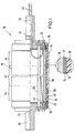
- Fig. 1 shows, in semisectional view, a heated roller 10 with an electrically resistive heating layer 14 arranged on the periphery of heated roller 10.
- a heated roller of this type is used, e.g., in a laminating device of a color proofing system. Such heated rollers are also suited for use in heat fixing stations of copying machines to fix the toner image onto the copying paper. The heated roller is useful also in a number of other applications for heat treatment.
- the heated roller 10 shown in Fig. 1 is provided with a support tube 16 formed as a hollow cylinder and made, e.g., from steel or another preferably metallic material.
- support tube 16 is provided with fixing rings 18 made, e.g., from an epoxy resin.
- Fixing rings 18 are substantially formed as a circular cap having an upright axial edge. This cap has a concentric central opening formed therein so that only a continuous edge portion, projecting at a right angle, is left of the cap.
- Fixing rings 18 are mounted on the axial ends of support tube 16 while concentrically surrounding these ends.
- support tube 16 is formed with conically tapering portions so that the axial ends of support tube 16 have a smaller outer diameter than the rest of support tube 16.
- a respective spring ring 22 of a material having good electric conductivity is arranged between the fixing rings 18 and the axial ends of support tube 16.
- a spring ring 22 of this type is shown in Fig. 2 which will be explained later on.
- the fixing rings 18 for fixing the spring rings 22 between the upright edges of the fixing rings 18 and the axial ends of the support tube 16 are held by protective caps 24 having axes 26 received therein.
- the two caps 24 are connected to each other by tensioning screws 28 which extend in axial direction through the hollow cylindrical support tube 16.
- heated roller 10 is rotatably supported on a suitable structure, e.g., the housing of a laminating device of a color proofing system.
- a suitable structure e.g., the housing of a laminating device of a color proofing system.
- One of the two axes 26 is hollow.
- the electrical conductors 30, connecting the spring rings 22 to an electric energy supply means, extend through this hollow axis 26.
- a heat insulating layer 32 which is made, e.g., from a non-conductive ceramic material, is arranged between the outer face of support tube 16 and the resistive heating layer 14.
- This layer 32 has the electrically resistive heating layer 14 applied thereon, with the peripheral outer face of resistive heating layer 14 in turn carrying a further electrically insulating layer 34 made, e.g., from a ceramic material.
- On layer 34 there is provided a thicker layer 36 of an elastic material such as a rubber material.
- This layer 36 forming the outer face of heated roller 10, has a temperature sensor 38 and an electric safety fuse 40 embedded therein. For reasons of clarity, the electrical connection between these two elements is not shown in Fig. 1.
- the thickness of the electrically resistive heating layer 14 is varying.
- the central region 42 of resistive heating layer 14 is thicker than the two edge regions 44 of heated roller 10 which extend from central region 42 to the axial ends of support tube 16. Because of the thinner shape of resistive heating layer 14 in the edge regions 44, these thinner regions of resistive heating layer 14 will be heated more intensively than the central region 42. Since the heat dissipation at the axial ends of heated roller 10 is more rapid than in the central region 42, this configuration provides for a uniform distribution of the surface temperature.
- spring rings 22 are in contact with the electrically resistive heating layer 14 because they are pressed against the resistive heating layer 14 by the fixing rings 18.
- spring rings 22 act as electrodes for supply of electric potential, and for infeeding electrical current into resistive heating layer 14.
- Such a spring ring 22 is shown in Fig. 2.
- Spring ring 22 is made from a metallic material of good electric conductivity and is substantially provided as a spiral tension spring 45, its two ends being connected to each other at 46.
- spring ring 22 is divided into three spring portions 48, which, however, is not imperative; spring ring 22 can also be provided as a continuous helical line. On a plurality of locations (three locations in the example shown in Fig.
- electrical supply conductors 30, e.g., wires, are connected to spring ring 22 to obtain a substantially uniform supply of electric energy over the whole peripheral extension of spring ring 22.
- spring ring 22 In the non-tensioned relieved condition of spring ring 22, its inner diameter is smaller than the outer diameter of the axial ends of support tube 16. Therefore, spring ring 22 has to be tensioned for being placed onto the axial ends of support tube 16. Because of the restoring force generated when spring ring 22 is tensioned, spring ring 22 exerts a radially inward pressure force on support tube 16 and thus on resistive heating layer 14, thus safeguarding a mechanically reliable contact between spring ring 22 and resistive heating layer 14.
- Fig. 3 shows a second embodiment of a heated roller 50.
- heated roller 50 of Fig. 3 each of the fixing rings 52 arranged on the axial ends of the support tube 16 is provided as a radially outward continuous flange, of which the axial portion engages support tube 16 on the inside thereof.
- peripheral groove 54 In the peripheral surface of support tube 16, there is formed a peripheral groove 54 extending over 360°. Also in this region of peripheral groove 54, the outer surface of roller 16 is covered by the material of the electrically resistive heating layer.
- the spring ring 22 is arranged in peripheral groove 54. Peripheral groove 54 is closed by a rubberized outer layer 36 surrounding the whole support tube 16 from the outside. Otherwise, heated roller 50 has the same features as heated roller 10 shown in Fig. 1.
- Fig. 4 shows a third embodiment of a heated roller 60.
- the fixing rings 62 used in heated roller 60 are provided with a continuous receiving groove 64 which is open in the axial direction of heated roller 60.
- Receiving groove 64 is formed by two legs 66,68 of fixing ring 62, with the outer leg 66 having a larger axial dimension than the inner leg 68.
- outer leg 66 and support tube 16 are exemplified as having the spring ring 22 arranged therebetween, spring ring 22 being kept pressed against the outer face of support tube 16 provided with the resistive heating layer 14.
- the spring rings 22 engage the resistive heating layer 14 of support tube 16 in the region of the conically tapering portions 20 of support tube 16.
- the embodiment of the inventive heated roller according to Fig. 4 is particularly easily assembled.
Landscapes
- Physics & Mathematics (AREA)
- General Physics & Mathematics (AREA)
- Control Of Resistance Heating (AREA)
- Resistance Heating (AREA)
- Fixing For Electrophotography (AREA)
Applications Claiming Priority (2)
| Application Number | Priority Date | Filing Date | Title |
|---|---|---|---|
| DE4420094 | 1994-06-09 | ||
| DE4420094 | 1994-06-09 |
Publications (2)
| Publication Number | Publication Date |
|---|---|
| EP0687132A2 true EP0687132A2 (fr) | 1995-12-13 |
| EP0687132A3 EP0687132A3 (fr) | 1996-05-22 |
Family
ID=6520131
Family Applications (1)
| Application Number | Title | Priority Date | Filing Date |
|---|---|---|---|
| EP95108790A Ceased EP0687132A3 (fr) | 1994-06-09 | 1995-06-07 | Elément de chauffage comprenant une couche pourvant être chauffée électriquement |
Country Status (3)
| Country | Link |
|---|---|
| US (1) | US5726425A (fr) |
| EP (1) | EP0687132A3 (fr) |
| JP (1) | JPH07335370A (fr) |
Cited By (3)
| Publication number | Priority date | Publication date | Assignee | Title |
|---|---|---|---|---|
| EP0818124A4 (fr) * | 1995-03-31 | 1999-05-06 | D & K Custom Mach Design Inc | Ensemble rouleau chauffant |
| WO1999045746A1 (fr) * | 1998-03-03 | 1999-09-10 | American Roller Company | Ensemble de contacts de bouchon d'extremite destine a un rouleau de chauffage |
| EP1382928A3 (fr) * | 2002-07-15 | 2004-04-21 | Andreas Lewandowski | Rouleau chauffant, en particulier pour machines de lamination |
Families Citing this family (5)
| Publication number | Priority date | Publication date | Assignee | Title |
|---|---|---|---|---|
| US6440048B1 (en) * | 1998-12-31 | 2002-08-27 | Eastman Kodak Company | Low cost fuser rollers |
| EP2332654B1 (fr) * | 2009-12-09 | 2014-04-02 | F. Hoffmann-La Roche AG | Système et méthode pour cycler la température des échantillons liquides |
| CN115852451B (zh) * | 2022-11-29 | 2025-03-14 | 中国原子能科学研究院 | 电沉积电极的支撑装置 |
| CN115852462B (zh) * | 2022-11-29 | 2024-09-06 | 中国原子能科学研究院 | 电沉积电极的支撑装置 |
| JP2025018572A (ja) * | 2023-07-27 | 2025-02-06 | 株式会社リコー | 加熱装置、定着装置、乾燥装置および画像形成装置 |
Citations (6)
| Publication number | Priority date | Publication date | Assignee | Title |
|---|---|---|---|---|
| DE2337751B1 (de) | 1973-07-25 | 1975-01-23 | Hoechst Ag | Kontaktwaermefixiereinrichtung |
| US4820904A (en) | 1987-11-02 | 1989-04-11 | Eastman Kodak Company | Electrical contacting device for fusing roller |
| EP0470554A1 (fr) | 1990-08-09 | 1992-02-12 | Schwäbische Hüttenwerke Gesellschaft mit beschränkter Haftung | Rouleau avec dispositif chauffant |
| JPH04213480A (ja) | 1990-12-11 | 1992-08-04 | Ricoh Co Ltd | 定着装置 |
| JPH0535137A (ja) | 1991-08-01 | 1993-02-12 | Ricoh Co Ltd | 定着装置 |
| US5191381A (en) | 1991-08-12 | 1993-03-02 | Jie Yuan | PTC ceramic heat roller for fixing toner image |
Family Cites Families (12)
| Publication number | Priority date | Publication date | Assignee | Title |
|---|---|---|---|---|
| US1668381A (en) * | 1923-10-30 | 1928-05-01 | Gen Electric | Electrical connecter |
| DE470554C (de) * | 1927-08-25 | 1929-01-19 | Bernhard Hoitz Dipl Ing | Holzschaelmaschine |
| US3056101A (en) * | 1959-10-19 | 1962-09-25 | Mc Graw Edison Co | Rotary electric current interchange contact |
| US3401439A (en) * | 1965-05-19 | 1968-09-17 | Gen Binding Corp | Laminating apparatus |
| FR1574025A (fr) * | 1968-04-03 | 1969-07-11 | ||
| US4033654A (en) * | 1976-07-29 | 1977-07-05 | Automation Industries, Inc. | Electrical connector |
| US4395109A (en) * | 1979-06-11 | 1983-07-26 | Tokyo Shibaura Denki Kabushiki Kaisha | Fixing device for electronic duplicator machine |
| US4570055A (en) * | 1984-05-07 | 1986-02-11 | Raychem Corporation | Electrically heat-recoverable assembly |
| US4776070A (en) * | 1986-03-12 | 1988-10-11 | Hitachi Metals, Ltd. | Directly-heating roller for fixing toner images |
| US4801968A (en) * | 1986-03-18 | 1989-01-31 | Kabushiki Kaisha Toshiba | Fixing device including a heat roller having a device for heating a region of the roller corresponding to the width of an image forming medium |
| JPS63307489A (ja) * | 1987-06-09 | 1988-12-15 | Hitachi Metals Ltd | トナ−定着用ヒ−トロ−ル |
| JP3293986B2 (ja) * | 1993-12-27 | 2002-06-17 | 株式会社リコー | 発熱ローラ |
-
1995
- 1995-04-24 US US08/426,962 patent/US5726425A/en not_active Expired - Fee Related
- 1995-05-26 JP JP7127909A patent/JPH07335370A/ja active Pending
- 1995-06-07 EP EP95108790A patent/EP0687132A3/fr not_active Ceased
Patent Citations (6)
| Publication number | Priority date | Publication date | Assignee | Title |
|---|---|---|---|---|
| DE2337751B1 (de) | 1973-07-25 | 1975-01-23 | Hoechst Ag | Kontaktwaermefixiereinrichtung |
| US4820904A (en) | 1987-11-02 | 1989-04-11 | Eastman Kodak Company | Electrical contacting device for fusing roller |
| EP0470554A1 (fr) | 1990-08-09 | 1992-02-12 | Schwäbische Hüttenwerke Gesellschaft mit beschränkter Haftung | Rouleau avec dispositif chauffant |
| JPH04213480A (ja) | 1990-12-11 | 1992-08-04 | Ricoh Co Ltd | 定着装置 |
| JPH0535137A (ja) | 1991-08-01 | 1993-02-12 | Ricoh Co Ltd | 定着装置 |
| US5191381A (en) | 1991-08-12 | 1993-03-02 | Jie Yuan | PTC ceramic heat roller for fixing toner image |
Cited By (4)
| Publication number | Priority date | Publication date | Assignee | Title |
|---|---|---|---|---|
| EP0818124A4 (fr) * | 1995-03-31 | 1999-05-06 | D & K Custom Mach Design Inc | Ensemble rouleau chauffant |
| WO1999045746A1 (fr) * | 1998-03-03 | 1999-09-10 | American Roller Company | Ensemble de contacts de bouchon d'extremite destine a un rouleau de chauffage |
| US5990458A (en) * | 1998-03-03 | 1999-11-23 | American Roller Company | End cap contact assembly for a heater roller |
| EP1382928A3 (fr) * | 2002-07-15 | 2004-04-21 | Andreas Lewandowski | Rouleau chauffant, en particulier pour machines de lamination |
Also Published As
| Publication number | Publication date |
|---|---|
| JPH07335370A (ja) | 1995-12-22 |
| EP0687132A3 (fr) | 1996-05-22 |
| US5726425A (en) | 1998-03-10 |
Similar Documents
| Publication | Publication Date | Title |
|---|---|---|
| US5726425A (en) | Tubular Heating element with elastic electrode | |
| KR960007433B1 (ko) | 수지로 제조된 복합 튜브 | |
| EP0156046B1 (fr) | Dispositif de fixation à rouleau | |
| ATE285069T1 (de) | Kraftwandler | |
| GB1594818A (en) | Splice case adaptor | |
| WO1995001081A1 (fr) | Rouleau chauffant en ceramique a chauffage par zones | |
| ATE176369T1 (de) | Heizelement | |
| US5508790A (en) | Photoreceptor sheet and imaging system utilizing same | |
| US5532807A (en) | Heating roller having electrodes for supplying power to a heating element | |
| US6450088B1 (en) | Heat sealing apparatus for plastic bags | |
| US12059836B2 (en) | Heating system for heating a heat shrink component, heat shrink component, and method of assembling a heat shrink component | |
| KR100382658B1 (ko) | 전자사진 화상형성장치의 정착롤러 장치 | |
| JPH06258974A (ja) | 熱定着装置 | |
| JP3990883B2 (ja) | レーザープリンタ用定着ローラの電力供給構造,定着ローラ,及びレーザープリンタ | |
| US5081340A (en) | Heating elements for plastic film laminators | |
| US6587656B2 (en) | Heating roller assembly for electrophotographic printer and method of making the same | |
| US5990458A (en) | End cap contact assembly for a heater roller | |
| US6072979A (en) | Thermal roller of fuser | |
| US11695265B2 (en) | Heat shrink component with heat spreading layer, and method of assembly a heat shrink component | |
| JPH07239623A (ja) | 電子写真装置のトナー定着用熱ローラ | |
| JPH08292674A (ja) | 加熱ローラの製造方法 | |
| KR100477662B1 (ko) | 전자사진 화상형성장치의 정착 장치 | |
| JP2004246138A (ja) | 定着ローラ及びその製造方法 | |
| JPH06175528A (ja) | 熱定着装置 | |
| JPH08262901A (ja) | 定着ヒータ,定着装置および画像形成装置 |
Legal Events
| Date | Code | Title | Description |
|---|---|---|---|
| PUAI | Public reference made under article 153(3) epc to a published international application that has entered the european phase |
Free format text: ORIGINAL CODE: 0009012 |
|
| AK | Designated contracting states |
Kind code of ref document: A2 Designated state(s): DE FR GB IT |
|
| PUAL | Search report despatched |
Free format text: ORIGINAL CODE: 0009013 |
|
| AK | Designated contracting states |
Kind code of ref document: A3 Designated state(s): DE FR GB IT |
|
| 17P | Request for examination filed |
Effective date: 19961025 |
|
| 17Q | First examination report despatched |
Effective date: 19981008 |
|
| GRAG | Despatch of communication of intention to grant |
Free format text: ORIGINAL CODE: EPIDOS AGRA |
|
| STAA | Information on the status of an ep patent application or granted ep patent |
Free format text: STATUS: THE APPLICATION HAS BEEN REFUSED |
|
| 18R | Application refused |
Effective date: 20001224 |