EP0687452A1 - Prothèse cotyloidienne, son utilisation et instrument ancillaire pour sa mise en place - Google Patents
Prothèse cotyloidienne, son utilisation et instrument ancillaire pour sa mise en place Download PDFInfo
- Publication number
- EP0687452A1 EP0687452A1 EP95401386A EP95401386A EP0687452A1 EP 0687452 A1 EP0687452 A1 EP 0687452A1 EP 95401386 A EP95401386 A EP 95401386A EP 95401386 A EP95401386 A EP 95401386A EP 0687452 A1 EP0687452 A1 EP 0687452A1
- Authority
- EP
- European Patent Office
- Prior art keywords
- cup
- prosthesis
- acetabular
- template
- rod
- Prior art date
- Legal status (The legal status is an assumption and is not a legal conclusion. Google has not performed a legal analysis and makes no representation as to the accuracy of the status listed.)
- Withdrawn
Links
- 238000004873 anchoring Methods 0.000 claims abstract description 18
- 239000004033 plastic Substances 0.000 claims abstract description 6
- 229920003023 plastic Polymers 0.000 claims abstract description 6
- 238000005553 drilling Methods 0.000 claims description 31
- 210000000588 acetabulum Anatomy 0.000 claims description 29
- 210000000988 bone and bone Anatomy 0.000 claims description 15
- 230000002093 peripheral effect Effects 0.000 claims description 12
- 230000006835 compression Effects 0.000 claims description 5
- 238000007906 compression Methods 0.000 claims description 5
- 238000006073 displacement reaction Methods 0.000 claims description 4
- 238000009434 installation Methods 0.000 claims description 3
- 238000013508 migration Methods 0.000 claims description 3
- 230000005012 migration Effects 0.000 claims description 3
- 235000016623 Fragaria vesca Nutrition 0.000 claims 1
- 240000009088 Fragaria x ananassa Species 0.000 claims 1
- 235000011363 Fragaria x ananassa Nutrition 0.000 claims 1
- 239000007787 solid Substances 0.000 claims 1
- 239000002184 metal Substances 0.000 abstract description 2
- 101100327917 Caenorhabditis elegans chup-1 gene Proteins 0.000 description 47
- 238000003801 milling Methods 0.000 description 9
- 239000004698 Polyethylene Substances 0.000 description 3
- 238000013459 approach Methods 0.000 description 3
- -1 polyethylene Polymers 0.000 description 3
- 229920000573 polyethylene Polymers 0.000 description 3
- 208000006386 Bone Resorption Diseases 0.000 description 2
- 208000008558 Osteophyte Diseases 0.000 description 2
- 230000000903 blocking effect Effects 0.000 description 2
- 230000024279 bone resorption Effects 0.000 description 2
- 210000001624 hip Anatomy 0.000 description 2
- 210000001981 hip bone Anatomy 0.000 description 2
- 210000001621 ilium bone Anatomy 0.000 description 2
- 230000007774 longterm Effects 0.000 description 2
- 206010031264 Osteonecrosis Diseases 0.000 description 1
- 208000025747 Rheumatic disease Diseases 0.000 description 1
- 239000003082 abrasive agent Substances 0.000 description 1
- 230000006978 adaptation Effects 0.000 description 1
- 206010003246 arthritis Diseases 0.000 description 1
- 230000008512 biological response Effects 0.000 description 1
- 238000005422 blasting Methods 0.000 description 1
- 230000000740 bleeding effect Effects 0.000 description 1
- 210000000845 cartilage Anatomy 0.000 description 1
- 239000004568 cement Substances 0.000 description 1
- 229910052593 corundum Inorganic materials 0.000 description 1
- 239000010431 corundum Substances 0.000 description 1
- 230000007850 degeneration Effects 0.000 description 1
- 230000001627 detrimental effect Effects 0.000 description 1
- 210000002436 femur neck Anatomy 0.000 description 1
- 210000004394 hip joint Anatomy 0.000 description 1
- 239000007943 implant Substances 0.000 description 1
- 239000000463 material Substances 0.000 description 1
- 238000000034 method Methods 0.000 description 1
- 238000012986 modification Methods 0.000 description 1
- 230000004048 modification Effects 0.000 description 1
- 210000002445 nipple Anatomy 0.000 description 1
- 230000036316 preload Effects 0.000 description 1
- 238000002360 preparation method Methods 0.000 description 1
- 238000007634 remodeling Methods 0.000 description 1
- 238000002271 resection Methods 0.000 description 1
- 230000000552 rheumatic effect Effects 0.000 description 1
- 210000000689 upper leg Anatomy 0.000 description 1
Images




Classifications
-
- A—HUMAN NECESSITIES
- A61—MEDICAL OR VETERINARY SCIENCE; HYGIENE
- A61B—DIAGNOSIS; SURGERY; IDENTIFICATION
- A61B17/00—Surgical instruments, devices or methods
- A61B17/16—Instruments for performing osteoclasis; Drills or chisels for bones; Trepans
- A61B17/1662—Instruments for performing osteoclasis; Drills or chisels for bones; Trepans for particular parts of the body
- A61B17/1664—Instruments for performing osteoclasis; Drills or chisels for bones; Trepans for particular parts of the body for the hip
- A61B17/1666—Instruments for performing osteoclasis; Drills or chisels for bones; Trepans for particular parts of the body for the hip for the acetabulum
-
- A—HUMAN NECESSITIES
- A61—MEDICAL OR VETERINARY SCIENCE; HYGIENE
- A61B—DIAGNOSIS; SURGERY; IDENTIFICATION
- A61B17/00—Surgical instruments, devices or methods
- A61B17/16—Instruments for performing osteoclasis; Drills or chisels for bones; Trepans
- A61B17/17—Guides or aligning means for drills, mills, pins or wires
- A61B17/1739—Guides or aligning means for drills, mills, pins or wires specially adapted for particular parts of the body
- A61B17/1742—Guides or aligning means for drills, mills, pins or wires specially adapted for particular parts of the body for the hip
- A61B17/1746—Guides or aligning means for drills, mills, pins or wires specially adapted for particular parts of the body for the hip for the acetabulum
-
- A—HUMAN NECESSITIES
- A61—MEDICAL OR VETERINARY SCIENCE; HYGIENE
- A61F—FILTERS IMPLANTABLE INTO BLOOD VESSELS; PROSTHESES; DEVICES PROVIDING PATENCY TO, OR PREVENTING COLLAPSING OF, TUBULAR STRUCTURES OF THE BODY, e.g. STENTS; ORTHOPAEDIC, NURSING OR CONTRACEPTIVE DEVICES; FOMENTATION; TREATMENT OR PROTECTION OF EYES OR EARS; BANDAGES, DRESSINGS OR ABSORBENT PADS; FIRST-AID KITS
- A61F2/00—Filters implantable into blood vessels; Prostheses, i.e. artificial substitutes or replacements for parts of the body; Appliances for connecting them with the body; Devices providing patency to, or preventing collapsing of, tubular structures of the body, e.g. stents
- A61F2/02—Prostheses implantable into the body
- A61F2/30—Joints
- A61F2/32—Joints for the hip
- A61F2/34—Acetabular cups
-
- A—HUMAN NECESSITIES
- A61—MEDICAL OR VETERINARY SCIENCE; HYGIENE
- A61F—FILTERS IMPLANTABLE INTO BLOOD VESSELS; PROSTHESES; DEVICES PROVIDING PATENCY TO, OR PREVENTING COLLAPSING OF, TUBULAR STRUCTURES OF THE BODY, e.g. STENTS; ORTHOPAEDIC, NURSING OR CONTRACEPTIVE DEVICES; FOMENTATION; TREATMENT OR PROTECTION OF EYES OR EARS; BANDAGES, DRESSINGS OR ABSORBENT PADS; FIRST-AID KITS
- A61F2/00—Filters implantable into blood vessels; Prostheses, i.e. artificial substitutes or replacements for parts of the body; Appliances for connecting them with the body; Devices providing patency to, or preventing collapsing of, tubular structures of the body, e.g. stents
- A61F2/02—Prostheses implantable into the body
- A61F2/30—Joints
- A61F2/46—Special tools for implanting artificial joints
- A61F2/4603—Special tools for implanting artificial joints for insertion or extraction of endoprosthetic joints or of accessories thereof
- A61F2/4609—Special tools for implanting artificial joints for insertion or extraction of endoprosthetic joints or of accessories thereof of acetabular cups
-
- A—HUMAN NECESSITIES
- A61—MEDICAL OR VETERINARY SCIENCE; HYGIENE
- A61B—DIAGNOSIS; SURGERY; IDENTIFICATION
- A61B17/00—Surgical instruments, devices or methods
- A61B17/56—Surgical instruments or methods for treatment of bones or joints; Devices specially adapted therefor
- A61B17/58—Surgical instruments or methods for treatment of bones or joints; Devices specially adapted therefor for osteosynthesis, e.g. bone plates, screws or setting implements
- A61B17/68—Internal fixation devices, including fasteners and spinal fixators, even if a part thereof projects from the skin
- A61B17/84—Fasteners therefor or fasteners being internal fixation devices
- A61B17/86—Pins or screws or threaded wires; nuts therefor
-
- A—HUMAN NECESSITIES
- A61—MEDICAL OR VETERINARY SCIENCE; HYGIENE
- A61F—FILTERS IMPLANTABLE INTO BLOOD VESSELS; PROSTHESES; DEVICES PROVIDING PATENCY TO, OR PREVENTING COLLAPSING OF, TUBULAR STRUCTURES OF THE BODY, e.g. STENTS; ORTHOPAEDIC, NURSING OR CONTRACEPTIVE DEVICES; FOMENTATION; TREATMENT OR PROTECTION OF EYES OR EARS; BANDAGES, DRESSINGS OR ABSORBENT PADS; FIRST-AID KITS
- A61F2/00—Filters implantable into blood vessels; Prostheses, i.e. artificial substitutes or replacements for parts of the body; Appliances for connecting them with the body; Devices providing patency to, or preventing collapsing of, tubular structures of the body, e.g. stents
- A61F2/02—Prostheses implantable into the body
- A61F2/30—Joints
- A61F2/46—Special tools for implanting artificial joints
- A61F2/4603—Special tools for implanting artificial joints for insertion or extraction of endoprosthetic joints or of accessories thereof
-
- A—HUMAN NECESSITIES
- A61—MEDICAL OR VETERINARY SCIENCE; HYGIENE
- A61F—FILTERS IMPLANTABLE INTO BLOOD VESSELS; PROSTHESES; DEVICES PROVIDING PATENCY TO, OR PREVENTING COLLAPSING OF, TUBULAR STRUCTURES OF THE BODY, e.g. STENTS; ORTHOPAEDIC, NURSING OR CONTRACEPTIVE DEVICES; FOMENTATION; TREATMENT OR PROTECTION OF EYES OR EARS; BANDAGES, DRESSINGS OR ABSORBENT PADS; FIRST-AID KITS
- A61F2/00—Filters implantable into blood vessels; Prostheses, i.e. artificial substitutes or replacements for parts of the body; Appliances for connecting them with the body; Devices providing patency to, or preventing collapsing of, tubular structures of the body, e.g. stents
- A61F2/02—Prostheses implantable into the body
- A61F2/30—Joints
- A61F2002/30001—Additional features of subject-matter classified in A61F2/28, A61F2/30 and subgroups thereof
- A61F2002/30316—The prosthesis having different structural features at different locations within the same prosthesis; Connections between prosthetic parts; Special structural features of bone or joint prostheses not otherwise provided for
- A61F2002/30329—Connections or couplings between prosthetic parts, e.g. between modular parts; Connecting elements
- A61F2002/30331—Connections or couplings between prosthetic parts, e.g. between modular parts; Connecting elements made by longitudinally pushing a protrusion into a complementarily-shaped recess, e.g. held by friction fit
-
- A—HUMAN NECESSITIES
- A61—MEDICAL OR VETERINARY SCIENCE; HYGIENE
- A61F—FILTERS IMPLANTABLE INTO BLOOD VESSELS; PROSTHESES; DEVICES PROVIDING PATENCY TO, OR PREVENTING COLLAPSING OF, TUBULAR STRUCTURES OF THE BODY, e.g. STENTS; ORTHOPAEDIC, NURSING OR CONTRACEPTIVE DEVICES; FOMENTATION; TREATMENT OR PROTECTION OF EYES OR EARS; BANDAGES, DRESSINGS OR ABSORBENT PADS; FIRST-AID KITS
- A61F2/00—Filters implantable into blood vessels; Prostheses, i.e. artificial substitutes or replacements for parts of the body; Appliances for connecting them with the body; Devices providing patency to, or preventing collapsing of, tubular structures of the body, e.g. stents
- A61F2/02—Prostheses implantable into the body
- A61F2/30—Joints
- A61F2002/30001—Additional features of subject-matter classified in A61F2/28, A61F2/30 and subgroups thereof
- A61F2002/30316—The prosthesis having different structural features at different locations within the same prosthesis; Connections between prosthetic parts; Special structural features of bone or joint prostheses not otherwise provided for
- A61F2002/30329—Connections or couplings between prosthetic parts, e.g. between modular parts; Connecting elements
- A61F2002/30331—Connections or couplings between prosthetic parts, e.g. between modular parts; Connecting elements made by longitudinally pushing a protrusion into a complementarily-shaped recess, e.g. held by friction fit
- A61F2002/30354—Cylindrically-shaped protrusion and recess, e.g. cylinder of circular basis
-
- A—HUMAN NECESSITIES
- A61—MEDICAL OR VETERINARY SCIENCE; HYGIENE
- A61F—FILTERS IMPLANTABLE INTO BLOOD VESSELS; PROSTHESES; DEVICES PROVIDING PATENCY TO, OR PREVENTING COLLAPSING OF, TUBULAR STRUCTURES OF THE BODY, e.g. STENTS; ORTHOPAEDIC, NURSING OR CONTRACEPTIVE DEVICES; FOMENTATION; TREATMENT OR PROTECTION OF EYES OR EARS; BANDAGES, DRESSINGS OR ABSORBENT PADS; FIRST-AID KITS
- A61F2/00—Filters implantable into blood vessels; Prostheses, i.e. artificial substitutes or replacements for parts of the body; Appliances for connecting them with the body; Devices providing patency to, or preventing collapsing of, tubular structures of the body, e.g. stents
- A61F2/02—Prostheses implantable into the body
- A61F2/30—Joints
- A61F2002/30001—Additional features of subject-matter classified in A61F2/28, A61F2/30 and subgroups thereof
- A61F2002/30316—The prosthesis having different structural features at different locations within the same prosthesis; Connections between prosthetic parts; Special structural features of bone or joint prostheses not otherwise provided for
- A61F2002/30329—Connections or couplings between prosthetic parts, e.g. between modular parts; Connecting elements
- A61F2002/30331—Connections or couplings between prosthetic parts, e.g. between modular parts; Connecting elements made by longitudinally pushing a protrusion into a complementarily-shaped recess, e.g. held by friction fit
- A61F2002/30362—Connections or couplings between prosthetic parts, e.g. between modular parts; Connecting elements made by longitudinally pushing a protrusion into a complementarily-shaped recess, e.g. held by friction fit with possibility of relative movement between the protrusion and the recess
- A61F2002/30364—Rotation about the common longitudinal axis
- A61F2002/30367—Rotation about the common longitudinal axis with additional means for preventing said rotation
-
- A—HUMAN NECESSITIES
- A61—MEDICAL OR VETERINARY SCIENCE; HYGIENE
- A61F—FILTERS IMPLANTABLE INTO BLOOD VESSELS; PROSTHESES; DEVICES PROVIDING PATENCY TO, OR PREVENTING COLLAPSING OF, TUBULAR STRUCTURES OF THE BODY, e.g. STENTS; ORTHOPAEDIC, NURSING OR CONTRACEPTIVE DEVICES; FOMENTATION; TREATMENT OR PROTECTION OF EYES OR EARS; BANDAGES, DRESSINGS OR ABSORBENT PADS; FIRST-AID KITS
- A61F2/00—Filters implantable into blood vessels; Prostheses, i.e. artificial substitutes or replacements for parts of the body; Appliances for connecting them with the body; Devices providing patency to, or preventing collapsing of, tubular structures of the body, e.g. stents
- A61F2/02—Prostheses implantable into the body
- A61F2/30—Joints
- A61F2002/30001—Additional features of subject-matter classified in A61F2/28, A61F2/30 and subgroups thereof
- A61F2002/30316—The prosthesis having different structural features at different locations within the same prosthesis; Connections between prosthetic parts; Special structural features of bone or joint prostheses not otherwise provided for
- A61F2002/30329—Connections or couplings between prosthetic parts, e.g. between modular parts; Connecting elements
- A61F2002/30331—Connections or couplings between prosthetic parts, e.g. between modular parts; Connecting elements made by longitudinally pushing a protrusion into a complementarily-shaped recess, e.g. held by friction fit
- A61F2002/30378—Spherically-shaped protrusion and recess
-
- A—HUMAN NECESSITIES
- A61—MEDICAL OR VETERINARY SCIENCE; HYGIENE
- A61F—FILTERS IMPLANTABLE INTO BLOOD VESSELS; PROSTHESES; DEVICES PROVIDING PATENCY TO, OR PREVENTING COLLAPSING OF, TUBULAR STRUCTURES OF THE BODY, e.g. STENTS; ORTHOPAEDIC, NURSING OR CONTRACEPTIVE DEVICES; FOMENTATION; TREATMENT OR PROTECTION OF EYES OR EARS; BANDAGES, DRESSINGS OR ABSORBENT PADS; FIRST-AID KITS
- A61F2/00—Filters implantable into blood vessels; Prostheses, i.e. artificial substitutes or replacements for parts of the body; Appliances for connecting them with the body; Devices providing patency to, or preventing collapsing of, tubular structures of the body, e.g. stents
- A61F2/02—Prostheses implantable into the body
- A61F2/30—Joints
- A61F2002/30001—Additional features of subject-matter classified in A61F2/28, A61F2/30 and subgroups thereof
- A61F2002/30316—The prosthesis having different structural features at different locations within the same prosthesis; Connections between prosthetic parts; Special structural features of bone or joint prostheses not otherwise provided for
- A61F2002/30329—Connections or couplings between prosthetic parts, e.g. between modular parts; Connecting elements
- A61F2002/30476—Connections or couplings between prosthetic parts, e.g. between modular parts; Connecting elements locked by an additional locking mechanism
- A61F2002/30505—Connections or couplings between prosthetic parts, e.g. between modular parts; Connecting elements locked by an additional locking mechanism spring biased
-
- A—HUMAN NECESSITIES
- A61—MEDICAL OR VETERINARY SCIENCE; HYGIENE
- A61F—FILTERS IMPLANTABLE INTO BLOOD VESSELS; PROSTHESES; DEVICES PROVIDING PATENCY TO, OR PREVENTING COLLAPSING OF, TUBULAR STRUCTURES OF THE BODY, e.g. STENTS; ORTHOPAEDIC, NURSING OR CONTRACEPTIVE DEVICES; FOMENTATION; TREATMENT OR PROTECTION OF EYES OR EARS; BANDAGES, DRESSINGS OR ABSORBENT PADS; FIRST-AID KITS
- A61F2/00—Filters implantable into blood vessels; Prostheses, i.e. artificial substitutes or replacements for parts of the body; Appliances for connecting them with the body; Devices providing patency to, or preventing collapsing of, tubular structures of the body, e.g. stents
- A61F2/02—Prostheses implantable into the body
- A61F2/30—Joints
- A61F2002/30001—Additional features of subject-matter classified in A61F2/28, A61F2/30 and subgroups thereof
- A61F2002/30316—The prosthesis having different structural features at different locations within the same prosthesis; Connections between prosthetic parts; Special structural features of bone or joint prostheses not otherwise provided for
- A61F2002/30329—Connections or couplings between prosthetic parts, e.g. between modular parts; Connecting elements
- A61F2002/30476—Connections or couplings between prosthetic parts, e.g. between modular parts; Connecting elements locked by an additional locking mechanism
- A61F2002/30514—Connections or couplings between prosthetic parts, e.g. between modular parts; Connecting elements locked by an additional locking mechanism using a locking washer
-
- A—HUMAN NECESSITIES
- A61—MEDICAL OR VETERINARY SCIENCE; HYGIENE
- A61F—FILTERS IMPLANTABLE INTO BLOOD VESSELS; PROSTHESES; DEVICES PROVIDING PATENCY TO, OR PREVENTING COLLAPSING OF, TUBULAR STRUCTURES OF THE BODY, e.g. STENTS; ORTHOPAEDIC, NURSING OR CONTRACEPTIVE DEVICES; FOMENTATION; TREATMENT OR PROTECTION OF EYES OR EARS; BANDAGES, DRESSINGS OR ABSORBENT PADS; FIRST-AID KITS
- A61F2/00—Filters implantable into blood vessels; Prostheses, i.e. artificial substitutes or replacements for parts of the body; Appliances for connecting them with the body; Devices providing patency to, or preventing collapsing of, tubular structures of the body, e.g. stents
- A61F2/02—Prostheses implantable into the body
- A61F2/30—Joints
- A61F2002/30001—Additional features of subject-matter classified in A61F2/28, A61F2/30 and subgroups thereof
- A61F2002/30316—The prosthesis having different structural features at different locations within the same prosthesis; Connections between prosthetic parts; Special structural features of bone or joint prostheses not otherwise provided for
- A61F2002/30535—Special structural features of bone or joint prostheses not otherwise provided for
- A61F2002/30537—Special structural features of bone or joint prostheses not otherwise provided for adjustable
- A61F2002/30538—Special structural features of bone or joint prostheses not otherwise provided for adjustable for adjusting angular orientation
- A61F2002/3054—Special structural features of bone or joint prostheses not otherwise provided for adjustable for adjusting angular orientation about a connection axis or implantation axis for selecting any one of a plurality of radial orientations between two modular parts, e.g. Morse taper connections, at discrete positions, angular positions or continuous positions
-
- A—HUMAN NECESSITIES
- A61—MEDICAL OR VETERINARY SCIENCE; HYGIENE
- A61F—FILTERS IMPLANTABLE INTO BLOOD VESSELS; PROSTHESES; DEVICES PROVIDING PATENCY TO, OR PREVENTING COLLAPSING OF, TUBULAR STRUCTURES OF THE BODY, e.g. STENTS; ORTHOPAEDIC, NURSING OR CONTRACEPTIVE DEVICES; FOMENTATION; TREATMENT OR PROTECTION OF EYES OR EARS; BANDAGES, DRESSINGS OR ABSORBENT PADS; FIRST-AID KITS
- A61F2/00—Filters implantable into blood vessels; Prostheses, i.e. artificial substitutes or replacements for parts of the body; Appliances for connecting them with the body; Devices providing patency to, or preventing collapsing of, tubular structures of the body, e.g. stents
- A61F2/02—Prostheses implantable into the body
- A61F2/30—Joints
- A61F2002/30001—Additional features of subject-matter classified in A61F2/28, A61F2/30 and subgroups thereof
- A61F2002/30316—The prosthesis having different structural features at different locations within the same prosthesis; Connections between prosthetic parts; Special structural features of bone or joint prostheses not otherwise provided for
- A61F2002/30535—Special structural features of bone or joint prostheses not otherwise provided for
- A61F2002/30594—Special structural features of bone or joint prostheses not otherwise provided for slotted, e.g. radial or meridian slot ending in a polar aperture, non-polar slots, horizontal or arcuate slots
-
- A—HUMAN NECESSITIES
- A61—MEDICAL OR VETERINARY SCIENCE; HYGIENE
- A61F—FILTERS IMPLANTABLE INTO BLOOD VESSELS; PROSTHESES; DEVICES PROVIDING PATENCY TO, OR PREVENTING COLLAPSING OF, TUBULAR STRUCTURES OF THE BODY, e.g. STENTS; ORTHOPAEDIC, NURSING OR CONTRACEPTIVE DEVICES; FOMENTATION; TREATMENT OR PROTECTION OF EYES OR EARS; BANDAGES, DRESSINGS OR ABSORBENT PADS; FIRST-AID KITS
- A61F2/00—Filters implantable into blood vessels; Prostheses, i.e. artificial substitutes or replacements for parts of the body; Appliances for connecting them with the body; Devices providing patency to, or preventing collapsing of, tubular structures of the body, e.g. stents
- A61F2/02—Prostheses implantable into the body
- A61F2/30—Joints
- A61F2/30767—Special external or bone-contacting surface, e.g. coating for improving bone ingrowth
- A61F2/30771—Special external or bone-contacting surface, e.g. coating for improving bone ingrowth applied in original prostheses, e.g. holes or grooves
- A61F2002/30772—Apertures or holes, e.g. of circular cross section
- A61F2002/30784—Plurality of holes
- A61F2002/30787—Plurality of holes inclined obliquely with respect to each other
-
- A—HUMAN NECESSITIES
- A61—MEDICAL OR VETERINARY SCIENCE; HYGIENE
- A61F—FILTERS IMPLANTABLE INTO BLOOD VESSELS; PROSTHESES; DEVICES PROVIDING PATENCY TO, OR PREVENTING COLLAPSING OF, TUBULAR STRUCTURES OF THE BODY, e.g. STENTS; ORTHOPAEDIC, NURSING OR CONTRACEPTIVE DEVICES; FOMENTATION; TREATMENT OR PROTECTION OF EYES OR EARS; BANDAGES, DRESSINGS OR ABSORBENT PADS; FIRST-AID KITS
- A61F2/00—Filters implantable into blood vessels; Prostheses, i.e. artificial substitutes or replacements for parts of the body; Appliances for connecting them with the body; Devices providing patency to, or preventing collapsing of, tubular structures of the body, e.g. stents
- A61F2/02—Prostheses implantable into the body
- A61F2/30—Joints
- A61F2/30767—Special external or bone-contacting surface, e.g. coating for improving bone ingrowth
- A61F2/30771—Special external or bone-contacting surface, e.g. coating for improving bone ingrowth applied in original prostheses, e.g. holes or grooves
- A61F2002/30772—Apertures or holes, e.g. of circular cross section
- A61F2002/3079—Stepped or enlarged apertures, e.g. having discrete diameter changes
-
- A—HUMAN NECESSITIES
- A61—MEDICAL OR VETERINARY SCIENCE; HYGIENE
- A61F—FILTERS IMPLANTABLE INTO BLOOD VESSELS; PROSTHESES; DEVICES PROVIDING PATENCY TO, OR PREVENTING COLLAPSING OF, TUBULAR STRUCTURES OF THE BODY, e.g. STENTS; ORTHOPAEDIC, NURSING OR CONTRACEPTIVE DEVICES; FOMENTATION; TREATMENT OR PROTECTION OF EYES OR EARS; BANDAGES, DRESSINGS OR ABSORBENT PADS; FIRST-AID KITS
- A61F2/00—Filters implantable into blood vessels; Prostheses, i.e. artificial substitutes or replacements for parts of the body; Appliances for connecting them with the body; Devices providing patency to, or preventing collapsing of, tubular structures of the body, e.g. stents
- A61F2/02—Prostheses implantable into the body
- A61F2/30—Joints
- A61F2/30767—Special external or bone-contacting surface, e.g. coating for improving bone ingrowth
- A61F2/30771—Special external or bone-contacting surface, e.g. coating for improving bone ingrowth applied in original prostheses, e.g. holes or grooves
- A61F2002/30878—Special external or bone-contacting surface, e.g. coating for improving bone ingrowth applied in original prostheses, e.g. holes or grooves with non-sharp protrusions, for instance contacting the bone for anchoring, e.g. keels, pegs, pins, posts, shanks, stems, struts
- A61F2002/30879—Ribs
-
- A—HUMAN NECESSITIES
- A61—MEDICAL OR VETERINARY SCIENCE; HYGIENE
- A61F—FILTERS IMPLANTABLE INTO BLOOD VESSELS; PROSTHESES; DEVICES PROVIDING PATENCY TO, OR PREVENTING COLLAPSING OF, TUBULAR STRUCTURES OF THE BODY, e.g. STENTS; ORTHOPAEDIC, NURSING OR CONTRACEPTIVE DEVICES; FOMENTATION; TREATMENT OR PROTECTION OF EYES OR EARS; BANDAGES, DRESSINGS OR ABSORBENT PADS; FIRST-AID KITS
- A61F2/00—Filters implantable into blood vessels; Prostheses, i.e. artificial substitutes or replacements for parts of the body; Appliances for connecting them with the body; Devices providing patency to, or preventing collapsing of, tubular structures of the body, e.g. stents
- A61F2/02—Prostheses implantable into the body
- A61F2/30—Joints
- A61F2/30767—Special external or bone-contacting surface, e.g. coating for improving bone ingrowth
- A61F2/30771—Special external or bone-contacting surface, e.g. coating for improving bone ingrowth applied in original prostheses, e.g. holes or grooves
- A61F2002/30878—Special external or bone-contacting surface, e.g. coating for improving bone ingrowth applied in original prostheses, e.g. holes or grooves with non-sharp protrusions, for instance contacting the bone for anchoring, e.g. keels, pegs, pins, posts, shanks, stems, struts
- A61F2002/30891—Plurality of protrusions
- A61F2002/30894—Plurality of protrusions inclined obliquely with respect to each other
-
- A—HUMAN NECESSITIES
- A61—MEDICAL OR VETERINARY SCIENCE; HYGIENE
- A61F—FILTERS IMPLANTABLE INTO BLOOD VESSELS; PROSTHESES; DEVICES PROVIDING PATENCY TO, OR PREVENTING COLLAPSING OF, TUBULAR STRUCTURES OF THE BODY, e.g. STENTS; ORTHOPAEDIC, NURSING OR CONTRACEPTIVE DEVICES; FOMENTATION; TREATMENT OR PROTECTION OF EYES OR EARS; BANDAGES, DRESSINGS OR ABSORBENT PADS; FIRST-AID KITS
- A61F2/00—Filters implantable into blood vessels; Prostheses, i.e. artificial substitutes or replacements for parts of the body; Appliances for connecting them with the body; Devices providing patency to, or preventing collapsing of, tubular structures of the body, e.g. stents
- A61F2/02—Prostheses implantable into the body
- A61F2/30—Joints
- A61F2/32—Joints for the hip
- A61F2/34—Acetabular cups
- A61F2002/3401—Acetabular cups with radial apertures, e.g. radial bores for receiving fixation screws
-
- A—HUMAN NECESSITIES
- A61—MEDICAL OR VETERINARY SCIENCE; HYGIENE
- A61F—FILTERS IMPLANTABLE INTO BLOOD VESSELS; PROSTHESES; DEVICES PROVIDING PATENCY TO, OR PREVENTING COLLAPSING OF, TUBULAR STRUCTURES OF THE BODY, e.g. STENTS; ORTHOPAEDIC, NURSING OR CONTRACEPTIVE DEVICES; FOMENTATION; TREATMENT OR PROTECTION OF EYES OR EARS; BANDAGES, DRESSINGS OR ABSORBENT PADS; FIRST-AID KITS
- A61F2/00—Filters implantable into blood vessels; Prostheses, i.e. artificial substitutes or replacements for parts of the body; Appliances for connecting them with the body; Devices providing patency to, or preventing collapsing of, tubular structures of the body, e.g. stents
- A61F2/02—Prostheses implantable into the body
- A61F2/30—Joints
- A61F2/32—Joints for the hip
- A61F2/34—Acetabular cups
- A61F2002/3401—Acetabular cups with radial apertures, e.g. radial bores for receiving fixation screws
- A61F2002/3403—Polar aperture
-
- A—HUMAN NECESSITIES
- A61—MEDICAL OR VETERINARY SCIENCE; HYGIENE
- A61F—FILTERS IMPLANTABLE INTO BLOOD VESSELS; PROSTHESES; DEVICES PROVIDING PATENCY TO, OR PREVENTING COLLAPSING OF, TUBULAR STRUCTURES OF THE BODY, e.g. STENTS; ORTHOPAEDIC, NURSING OR CONTRACEPTIVE DEVICES; FOMENTATION; TREATMENT OR PROTECTION OF EYES OR EARS; BANDAGES, DRESSINGS OR ABSORBENT PADS; FIRST-AID KITS
- A61F2/00—Filters implantable into blood vessels; Prostheses, i.e. artificial substitutes or replacements for parts of the body; Appliances for connecting them with the body; Devices providing patency to, or preventing collapsing of, tubular structures of the body, e.g. stents
- A61F2/02—Prostheses implantable into the body
- A61F2/30—Joints
- A61F2/32—Joints for the hip
- A61F2/34—Acetabular cups
- A61F2002/3412—Acetabular cups with pins or protrusions, e.g. non-sharp pins or protrusions projecting from a shell surface
-
- A—HUMAN NECESSITIES
- A61—MEDICAL OR VETERINARY SCIENCE; HYGIENE
- A61F—FILTERS IMPLANTABLE INTO BLOOD VESSELS; PROSTHESES; DEVICES PROVIDING PATENCY TO, OR PREVENTING COLLAPSING OF, TUBULAR STRUCTURES OF THE BODY, e.g. STENTS; ORTHOPAEDIC, NURSING OR CONTRACEPTIVE DEVICES; FOMENTATION; TREATMENT OR PROTECTION OF EYES OR EARS; BANDAGES, DRESSINGS OR ABSORBENT PADS; FIRST-AID KITS
- A61F2/00—Filters implantable into blood vessels; Prostheses, i.e. artificial substitutes or replacements for parts of the body; Appliances for connecting them with the body; Devices providing patency to, or preventing collapsing of, tubular structures of the body, e.g. stents
- A61F2/02—Prostheses implantable into the body
- A61F2/30—Joints
- A61F2/32—Joints for the hip
- A61F2/34—Acetabular cups
- A61F2002/3429—Acetabular cups with an integral peripheral collar or flange, e.g. oriented away from the shell centre line
-
- A—HUMAN NECESSITIES
- A61—MEDICAL OR VETERINARY SCIENCE; HYGIENE
- A61F—FILTERS IMPLANTABLE INTO BLOOD VESSELS; PROSTHESES; DEVICES PROVIDING PATENCY TO, OR PREVENTING COLLAPSING OF, TUBULAR STRUCTURES OF THE BODY, e.g. STENTS; ORTHOPAEDIC, NURSING OR CONTRACEPTIVE DEVICES; FOMENTATION; TREATMENT OR PROTECTION OF EYES OR EARS; BANDAGES, DRESSINGS OR ABSORBENT PADS; FIRST-AID KITS
- A61F2/00—Filters implantable into blood vessels; Prostheses, i.e. artificial substitutes or replacements for parts of the body; Appliances for connecting them with the body; Devices providing patency to, or preventing collapsing of, tubular structures of the body, e.g. stents
- A61F2/02—Prostheses implantable into the body
- A61F2/30—Joints
- A61F2/32—Joints for the hip
- A61F2/34—Acetabular cups
- A61F2002/348—Additional features
- A61F2002/3482—Two hemispherical halves having completely different structures
-
- A—HUMAN NECESSITIES
- A61—MEDICAL OR VETERINARY SCIENCE; HYGIENE
- A61F—FILTERS IMPLANTABLE INTO BLOOD VESSELS; PROSTHESES; DEVICES PROVIDING PATENCY TO, OR PREVENTING COLLAPSING OF, TUBULAR STRUCTURES OF THE BODY, e.g. STENTS; ORTHOPAEDIC, NURSING OR CONTRACEPTIVE DEVICES; FOMENTATION; TREATMENT OR PROTECTION OF EYES OR EARS; BANDAGES, DRESSINGS OR ABSORBENT PADS; FIRST-AID KITS
- A61F2/00—Filters implantable into blood vessels; Prostheses, i.e. artificial substitutes or replacements for parts of the body; Appliances for connecting them with the body; Devices providing patency to, or preventing collapsing of, tubular structures of the body, e.g. stents
- A61F2/02—Prostheses implantable into the body
- A61F2/30—Joints
- A61F2/46—Special tools for implanting artificial joints
- A61F2/4603—Special tools for implanting artificial joints for insertion or extraction of endoprosthetic joints or of accessories thereof
- A61F2002/4629—Special tools for implanting artificial joints for insertion or extraction of endoprosthetic joints or of accessories thereof connected to the endoprosthesis or implant via a threaded connection
-
- A—HUMAN NECESSITIES
- A61—MEDICAL OR VETERINARY SCIENCE; HYGIENE
- A61F—FILTERS IMPLANTABLE INTO BLOOD VESSELS; PROSTHESES; DEVICES PROVIDING PATENCY TO, OR PREVENTING COLLAPSING OF, TUBULAR STRUCTURES OF THE BODY, e.g. STENTS; ORTHOPAEDIC, NURSING OR CONTRACEPTIVE DEVICES; FOMENTATION; TREATMENT OR PROTECTION OF EYES OR EARS; BANDAGES, DRESSINGS OR ABSORBENT PADS; FIRST-AID KITS
- A61F2220/00—Fixations or connections for prostheses classified in groups A61F2/00 - A61F2/26 or A61F2/82 or A61F9/00 or A61F11/00 or subgroups thereof
- A61F2220/0025—Connections or couplings between prosthetic parts, e.g. between modular parts; Connecting elements
-
- A—HUMAN NECESSITIES
- A61—MEDICAL OR VETERINARY SCIENCE; HYGIENE
- A61F—FILTERS IMPLANTABLE INTO BLOOD VESSELS; PROSTHESES; DEVICES PROVIDING PATENCY TO, OR PREVENTING COLLAPSING OF, TUBULAR STRUCTURES OF THE BODY, e.g. STENTS; ORTHOPAEDIC, NURSING OR CONTRACEPTIVE DEVICES; FOMENTATION; TREATMENT OR PROTECTION OF EYES OR EARS; BANDAGES, DRESSINGS OR ABSORBENT PADS; FIRST-AID KITS
- A61F2220/00—Fixations or connections for prostheses classified in groups A61F2/00 - A61F2/26 or A61F2/82 or A61F9/00 or A61F11/00 or subgroups thereof
- A61F2220/0025—Connections or couplings between prosthetic parts, e.g. between modular parts; Connecting elements
- A61F2220/0033—Connections or couplings between prosthetic parts, e.g. between modular parts; Connecting elements made by longitudinally pushing a protrusion into a complementary-shaped recess, e.g. held by friction fit
Definitions
- the present invention relates to an acetabular prosthesis, its use in order to reduce wear of the prosthesis and the tilting thereof in the acetabulum, and to promote regular bone regrowth of the iliac bone, as well as ancillary instrumentation. for its implementation.
- Some prostheses consist for example of two elements, namely an acetabular cup, generally metallic, to be implanted in the acetabular cavity and an insert made of low-abrasive material, such as a plastic material such as polyethylene, fitted into the metallic cup, and in which insert is articulated the head of a femoral prosthesis rod implanted in turn in the medullary canal of the femur.
- an acetabular cup generally metallic
- an insert made of low-abrasive material such as a plastic material such as polyethylene
- the fixation of the cup in the natural acetabular cavity of an individual can be done with or without cement.
- cementless fixation it is necessary to provide primary anchoring means on the abovementioned elements so that, as soon as the prosthesis elements are in place, the fixation of the prosthesis in the adjacent iliac bone is sufficient to allow the operated individual to resume walking quickly, to recover the mobility of his hip at the end of the operation and to allow him to immediately get back on track.
- the secondary anchorage will subsequently develop over time by bone regrowth between the surface of the cup and the adjacent bone in which it is implanted to form a bone bond, which in the long term constitutes the fixation of the prosthesis.
- Primary anchoring means of the acetabular cup are already known in the bony acetabulum, which comprise at least one screw engaged through an opening made in the wall of said cup.
- connection between the core and the metal cup is generally effected by stapling the core on the lower edge of the cup.
- the prostheses currently known do not include means ensuring perfect primary stability of the prosthesis in the acetabulum and a tilting of the prosthesis can occur in the acetabular cavity.
- the quality of the primary and secondary anchoring of the prosthesis in the acetabular cavity depends on the quality of the imprint which is formed in the osseous acetabulum and on the means of placing the prosthesis therein.
- known ancillary medical instruments do not make it possible to obtain a good quality impression in the acetabulum.
- the present invention therefore aims to eliminate the aforementioned drawbacks and to propose an acetabular prosthesis making it possible to reduce its wear, its tilting and to promote bone regrowth.
- the present invention relates to an acetabular prosthesis consisting of a cup, for example metallic, comprising primary anchoring means in the acetabular cavity and externally having a generally convex shape and internally a substantially concave housing, and an insert, for example made of plastic, provided with means of connection with the cup and having externally a shape corresponding to said housing in which the insert is received and internally a hemispherical bearing surface intended to receive the head of a stem of femoral prosthesis, characterized in that it comprises elastic means for generating a prestress between the acetabulum, the cup and the insert.
- the above-mentioned elastic means are formed of at least one slot made through the wall of the cup from the vicinity of the pole of the latter up to its lower peripheral edge, according to a meridian, to allow the expansion and retraction of the cup relative to an intermediate position of rest.
- the meridian slot (s) are formed in only one half of the cup, opposite the other half of the cup comprising the primary anchoring means in the acetabulum.
- the elastic means of the prosthesis of the invention establishing a prestress between the prosthesis and the acetabulum, this prestress could cause bone resorption. Consequently, it is advantageous to provide these elastic means in the half of the cup intended to be received in the lower elastic part of the acetabulum comprising the horns.
- the primary anchoring means comprise an arcuate boss concentric with the cup and projecting from the external surface of the cup, through which boss are provided through holes to accommodate fixing screws. of the cup in the bone cup.
- the cup of the acetabular prosthesis may advantageously include, at its lower peripheral edge, a circular collar intended to come to bear against a corresponding housing formed at the edge of the acetabulum.
- the internal housing of the cup has from the lower peripheral edge a cylindrical part which is extended by a truncated spherical part in the vicinity of the pole of the cup by a flat surface and parallel to the equatorial plane of the cup, to prevent the core from tipping over.
- the cup may further include under the aforementioned collar at least one lug projecting downwards capable of being housed in a notch of corresponding shape formed in a peripheral border surrounding the base of the insert of the acetabular prosthesis, to prevent any rotation of the insert in the cup around the polar axis.
- each notch and of the associated lug can be substantially different, in order to establish a tightening and a blocking between the cup and the insert.
- the present invention also relates to the use of an acetabular prosthesis comprising elastic prestressing means to reduce wear between the cup and the insert.
- the present invention also relates to the use of an acetabular prosthesis comprising elastic prestressing means to reduce the creep of the core and the detachment of plastic debris.
- the invention also relates to the use of an acetabular prosthesis comprising a circular flange at the equatorial plane of the cup to reduce the tilting of the latter and the migration of the cup towards the bottom of the acetabular cavity.
- the present invention further relates to the use of an acetabular prosthesis as defined above to reduce micro-displacements of the cup in the acetabulum and promote bone regrowth.
- the present invention finally relates to ancillary instrumentation for the establishment of the acetabular prosthesis as defined above, comprising in particular a drilling template and a template holder, characterized in that the drilling template consists of a piece massive cylindrospherical comprising at least two holes made from its underside, a first hole opening on the outer spherical face of the template to dig a bore which corresponds to the boss of the acetabular cup and which is obtained using a cutter passing through said first hole, and the second hole passing axially through the template to pierce a centro-cotyloid orifice in the acetabular cavity.
- the drilling template consists of a piece massive cylindrospherical comprising at least two holes made from its underside, a first hole opening on the outer spherical face of the template to dig a bore which corresponds to the boss of the acetabular cup and which is obtained using a cutter passing through said first hole, and the second hole passing axially through the template to
- the drilling template advantageously includes a third hole which opens onto the external spherical face of the template and which is spaced from the first hole of an arc corresponding to the boss of the acetabular cup.
- the drilling template may further include a fourth hole associated with a pusher and intended to receive and retain a stud for fixing the template holder.
- the ancillary instrumentation comprises a circular cutter capable of digging a circular housing in the coxal bone to receive the circular flange of the acetabular cup, said cutter being supported by a cutter holder provided with an axially movable piston, the rod of which is capable of passing axially through the circular cutter and the head of which is housed in the third central hole of the aforementioned drilling template.
- the ancillary instrumentation comprises a cup holder which comprises a handle extending by a rod to a centering pin and a means of locking in rotation, about the axis of said stem, of a cup mounted on said nipple.
- This rotation blocking means may comprise a sleeve mounted to slide axially on said rod, and a slotted lug at a free end and mounted, preferably movable, through the head of the sleeve and perpendicular to the axis of the rod and substantially at neighborhood of the aforementioned stud.
- An elastic means can be provided between the handle and / or the rod of the cup holder and the sliding sleeve to urge the latter towards the centering pin.
- This elastic means may advantageously be a compression spring interposed between the rod and the sleeve and bearing at one end on a radial shoulder of the rod and at the other end against the abovementioned tab so as to both block the latter in position at through the head of the sleeve and urge the latter towards the aforementioned stud.
- Figure 1 is a perspective view of the cup of acetabular prosthesis of the invention.
- Figure 2 is a sectional view of the cup of Figure 1, along a meridian thereof.
- Figure 3 is a perspective view of the core of an acetabular prosthesis of the invention.
- FIG. 4 is a bottom view of the core of FIG. 3.
- Figure 5 is a top view, partially broken away, of a drilling template associated with a template holder of the ancillary instrumentation according to the invention.
- Figure 6 is a sectional view of the drilling template associated with the template holder of Figure 5, along the line VI-VI.
- Figure 7 is a sectional and partially exploded view of a centering pin and the drilling template of Figure 5, associated with a flexible cutter, along the line VII-VII.
- Figure 8 is a side view of a circular cutter of the ancillary instrumentation according to the invention.
- FIG. 9 is a side view, partially in section, of a milling cutter holder of the ancillary instrumentation of the invention, intended to carry the circular milling cutter of FIG. 8.
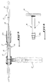
- Figure 10 is a side view of a cup holder of the ancillary instrumentation of the present invention.
- FIG. 11 is a partial view in axial section, along the line XI-XI of FIG. 12, of the cup of the invention associated with the cup holder of FIG. 10.
- FIG. 12 is a sectional view of the cup holder, along the line XII-XII of FIG. 11.
- Figures 13 and 14 are side views respectively of a cup impactor and a core holder.
- FIG. 15 is a side view of a universal handle intended to support the cup impactor of FIG. 11 and the core holder of FIG. 12.
- the acetabular prosthesis of the invention comprises a hollow cup 1 whose external surface 2 is generally hemispherical.
- a boss 3 in the form of a circular arc projects from the external surface 2 radially with respect to the center of the sphere delimiting the cup 1.
- the arc of the boss 3 extends over a large angle of the order of 120 °, which makes it possible to achieve an excellent primary anchoring of the cup 1 in the acetabular cavity, by means of three screws 4 passing through said boss 3.
- This boss also makes it possible to avoid any rotational movement of the cup 1 around its polar axis 5.
- each screw 4 is intended to be received in respective bores 6 which open into the internal housing 7 of the cup 1.
- the holes 6 have a slightly concave internal shape so that the head of the screws 4 can pivot inside its respective bore 6 to allow the surgeon to orient the screws 4 in a direction adapted to the hip (lines of force) where the prosthesis is to be implanted.
- the internal housing 7 of the cup 1 has a cylindrical lower part 8 which is extended by a spherical part 9 and ends at its top by a flat part 10 parallel to the equatorial plane 11 of the cup 1.
- a rounded and circular flange 12 projects externally from the lower peripheral edge or from the equatorial plane 11 of the cup 1.
- a thread 14 passes through the wall of the cup 1 perpendicular to the flat part 10 of the housing 7 to receive the externally threaded end 15a of a cup holder 15, shown in FIG. 10.
- the wall of the cup 1 also has a plurality of slots 17 formed along the meridians of the cup 1, from the vicinity of the pole 2a of the cup 1 up to the circular collar 12.
- These meridian slots 16 have their lower ends 16a open and their upper ends 16b closed and in the form of a circle in the vicinity of the pole 2a.
- the acetabular prosthesis of the invention further comprises an insert with the core 17 (see FIG. 3), for example made of polyethylene, having an external surface of a shape corresponding to the housing 7, namely a cylindrical part 8 ', a spherical part 9' and a flat part 10 '.
- the core 17 for example made of polyethylene, having an external surface of a shape corresponding to the housing 7, namely a cylindrical part 8 ', a spherical part 9' and a flat part 10 '.
- the particular shape of the housing 7 and of the external surface of the core 17 prevents any rotation of the latter in the cup 1 relative to an axis perpendicular to the polar axis 5.
- the core 17 further comprises a lower peripheral edge 18 which comes under the circular collar 12 of the cup 1, with little play.
- Notches 19 are formed through the edge 18 which extends in a substantially equatorial plane, to receive the lugs 13 of the cup 1, which prevents any relative rotation of the core 17 in the cup 1 relative to the polar axis 5, and which also makes it possible to retain the core 17.
- the core 17 has a hemispherical housing 20 formed from the underside 21 of the core 17, to receive the head of a femoral rod not shown.
- Two recesses 22 are formed diametrically in the core 17 from its underside 21 to receive two fixing pins 23a of a core holder 23 illustrated in FIG. 12.
- the surgeon After a known surgical preparation, the surgeon performs a reaming of the acetabulum using a cutter in the shape of a hemispherical rasp. The cup is reamed by removing all traces of cartilage and until a bleeding bone is obtained.
- the template holder 25 comprises a handle 26 connected to a support plate 27 by means of a central rod 28.
- the central rod 28 is fixed to the periphery of the lower face of the support plate 27, while the upper face of the plate 27 bears against the lower flat face 29 of the drilling template 24.
- the drilling template 24 has a generally spherical external surface 24a separated from its lower flat face 29 by a cylindrical part 24b.
- the curvature of the spherical external surface 24a is substantially the same, or even slightly less than the curvature of the external surface 2 of the cup 1 of the acetabular prosthesis of the invention.
- the plate 27 comprises axially a sleeve 30 which projects from the upper face of the plate 27 so as to fit into a hole 31 axially passing through the drilling template 24.
- the plate 27 further comprises a stud 32 radially spaced from the sleeve 30 which also projects from the upper face of the plate 27 so as to be received in another hole 33 formed through the template 24, parallel to the hole 31.
- the hole 33 is shown through in the drawings, but it can alternatively be blind.
- the stud 32 has a generally mushroom-shaped or alters so that its median part of reduced section cooperates with a pusher 34 (shown in the FIG. 5) to block the stud 32 in the hole of the drilling template 24.
- the pusher 34 comes into engagement against the stud 32 by screwing this pusher into a thread 35 formed radially with respect to the hole 33.
- the upper part of the hole 31 is internally threaded to receive a centering pin 36 shown in Figure 7 in the disassembled position.
- the drilling template 24 comprises two other through holes 37, internally threaded, spaced radially from the through hole 31 and axes parallel to the latter.
- These through holes 37 are intended to receive the head of a flexible cutter 38 in the form of a wick shown in FIG. 7.
- the two through holes 37 are spaced from one another in an arc corresponding to the boss 3 of the cup 1.
- the surgeon While holding the drilling template 24 with the template holder 25, drills a central acetabular hole in the acetabular cavity using a drill bit. drilling (not shown) passing through the sleeve 30 of the template holder 25 and the hole 31 of the template 24.
- the surgeon then introduces the flexible cutter 38 into the second hole 37 to form a second drilling in the acetabulum. It is possible to keep the template 24 stationary in rotation about its polar axis 24c by introducing a point in the first borehole, while the second borehole is being formed.
- the surgeon performs a bore corresponding to the boss 3 of the cup 1 by rotating the template 24 about its axis 24c, to bring the flexible cutter 38 from the second borehole to the first borehole.
- the surgeon then performs the resection of the osteophytes which overflow around the template 24 and the drilling of a peripheral circular housing at the entrance of the acetabulum using a circular milling cutter called shape 39 shown in FIG. 8.
- the circular milling cutter 39 has at one end a toothed ring 40 which is guided at its internal periphery by the cylindrical part 24b of the template 24 and which comes to fit around this part 24b to bore the aforementioned housing.
- the profile of the teeth of the cutter 39 is identical to the profile of the flange 12 of the cup 1.
- the circular cutter 39 is supported by a cutter holder 41 shown in FIG. 9.
- the milling cutter holder 41 has the general form of a "pistol” comprising a handle 42 surmounted by a guide tube 43 perpendicular to said handle 42.
- the guide tube 43 retains at one of its ends 43a the other end 39a of the circular milling cutter 39, opposite the end having the toothed crown 40.
- the cutter holder 41 further comprises a centering piston 44 consisting of an element 45 movable axially inside the guide tube 43 and manually actuated by a finger 46 which projects out of the guide tube 43, of a piston head 47 which projects axially out of the tube 43 and of a piston rod 48 connecting said head 47 to said movable element 45.
- the piston head 47 passes axially through the milling cutter 39 by means of a bore 49, so as to be received in the hole 31 of the template 24.
- the piston 44 therefore ensures axial pre-guiding of the cutter 39 during its approach phase, the cutter 39 then being guided by the cylindrical part 24b of the template 24.
- the cup holder 15 comprises a handle 15b extending by an elongated rod 15c up to the centering pin 15a onto which the thread 14 of the cup 1 is screwed.
- the cup holder 15 further comprises a sleeve 55 mounted to slide axially on the elongated rod 15c, the head 55a of the sleeve 15 being traversed by a slotted lug 56 which is movable in this head 55a in a direction perpendicular to the axis 57 of the rod 15c.
- the tab 56 moves in a housing 58 formed diametrically in the head 55a and comprises at a free longitudinal end a mortise 59, for example in the shape of a U, which is of shape substantially adapted to the lugs 13 of the cup 1 of the invention .
- the tab 56 further comprises an oblong through hole 60 through which the end 15d of the elongated rod 15c passes.
- the tab 56 and the sleeve 55 are therefore axially movable along the end 15d of the rod 15c.
- a helical compression spring 61 is mounted axially around the end 15d of the rod 15c and it is interposed between said end 15d and the internal wall of the sleeve 55.
- This compression spring 61 bears on an end turn on a radial shoulder 62 which separates the main body of the rod 15c from its end 15d and at the other end turn against the tab 56, by means of example of a support washer 63, to block the tab 56 in position through the head 55a of the sleeve 55 by pressure and friction.
- any other elastic means suitable for replacing the helical compression spring 61 could be provided as a variant.
- the assembly of the mortise 59 of the tab 56 with a lug 13 can be easily carried out in the following manner: after having screwed the stud 15a in the thread 14 of the cup 1, first of all a traction is exerted on the sleeve 55 to move it away from the centering pin 15a and then the sleeve 55 is released, after having correctly positioned the tab 56 through its housing 58, so that it comes to fit in the axial direction 57 with the associated lug 13.
- This characteristic is particularly advantageous because it avoids any risk of unscrewing the centering pin 15a relative to the cup 1, when the surgeon wants to rotate the cup 1 in the direction of unscrewing the stud 15a and that the cup 1 is inserted into the acetabular cavity.
- the rod 15c is assembled to the centering stud 15a by means of a pin 64 which passes diametrically through the end 15d and a separate piece 65 secured to the stud 15a, to allow mounting and dismounting easy from the spring 61 between the shoulder 62 and the tab 56.
- a support flange 66 separates the threaded stud 15a from the main body of the part 65 to bear against the flat part 10 of the cup 1.
- Correct positioning of the cup 1 in the cavity formed in the acetabulum is effected by inserting the projecting end of the stud 15a in the central acetabular hole and the boss 3 of the cup 1 in its receiving bore.
- the impression formed in the acetabulum has a slightly lower sphericity than that of the cup 1, so that the cup 1 retracts when it is inserted into the impression thanks to the elasticity provided by the meridian slots 16.
- the impactor of the cup 50 also includes a centering pin 51 intended to be screwed into the thread 14 of the cup 1 and has an external shape substantially corresponding to the housing 7 of the cup 1.
- the cup impactor 50 is supported at its end 52 by a universal handle 53 shown in FIG. 15.
- connection between the stud 15a and the internal thread 14 of the cup 1 may not be strong enough to withstand the aforementioned hammering.
- the surgeon then conventionally performs drilling holes in the acetabular cavity, through the holes 6 of the cup 1, for the installation of the fixing screws 4.
- the core 17 is finally adjusted by force in the cup 1, using the core holder 23 (shown in FIG. 14) which supports the core 17 by means of two pins 23a which are received in the recesses 22 of the core 17 and of a hemispherical boss 54 of a shape corresponding to the hemispherical internal housing 20 of the core 17.
- the cup 1 having undergone a retraction during its adjustment in the bone acetabulum, the cup 1 now undergoes an expansion during the adjustment of the core 17 in the housing 7 of the cup 1, which generates a preload between, of a on the one hand, the elastic lower part of the acetabulum and one half of the cup 1 and, on the other hand, the cup 1 and the core 17.
Landscapes
- Health & Medical Sciences (AREA)
- Orthopedic Medicine & Surgery (AREA)
- Life Sciences & Earth Sciences (AREA)
- Veterinary Medicine (AREA)
- Animal Behavior & Ethology (AREA)
- Surgery (AREA)
- Oral & Maxillofacial Surgery (AREA)
- Engineering & Computer Science (AREA)
- Biomedical Technology (AREA)
- Heart & Thoracic Surgery (AREA)
- Public Health (AREA)
- General Health & Medical Sciences (AREA)
- Transplantation (AREA)
- Nuclear Medicine, Radiotherapy & Molecular Imaging (AREA)
- Molecular Biology (AREA)
- Medical Informatics (AREA)
- Dentistry (AREA)
- Cardiology (AREA)
- Vascular Medicine (AREA)
- Physical Education & Sports Medicine (AREA)
- Prostheses (AREA)
Abstract
Description
- La présente invention concerne une prothèse cotyloïdienne, son utilisation en vue de réduire l'usure de la prothèse et le basculement de celle-ci dans le cotyle, et pour favoriser une repousse osseuse régulière de l'os iliaque, ainsi que l'instrumentation ancillaire pour sa mise en place.
- Lors d'une dégénérescence arthrosique ou rhumatismale, d'une ostéonécrose ou d'une fracture du col fémoral, il peut être nécessaire de remplacer l'articulation coxo-fémorale par une prothèse.
- Certaines prothèses sont constituées par exemple de deux éléments, à savoir une cupule cotyloïdienne, généralement métallique, à implanter dans la cavité cotyloïdienne osseuse et un insert en matériau peu abrasif, comme une matière plastique telle que le polyéthylène, emboîté dans la cupule métallique, et dans lequel insert est articulée la tête d'une tige de prothèse fémorale implantée quant à elle dans le canal médullaire du fémur.
- La fixation de la cupule dans la cavité cotyloïdienne naturelle osseuse d'un individu peut se faire avec ou sans ciment. Dans le cas d'une fixation sans ciment, il est nécessaire de prévoir sur les éléments précités des moyens d'ancrage primaires pour que, dès la mise en place des éléments de prothèse, la fixation de la prothèse dans l'os iliaque adjacent soit suffisante pour permettre à l' individu opéré de reprendre rapidement la marche, de récupérer la mobilité de sa hanche dès le terme de l'opération et de lui permettre aussitôt la remise en charge. L'ancrage secondaire se développera par la suite au cours du temps par repousse osseuse entre la surface de la cupule et l'os adjacent dans lequel elle est implantée pour former une liaison osseuse, ce qui constitue à long terme la fixation de la prothèse.
- Il est connu pour favoriser la repousse osseuse et donc améliorer l'ancrage secondaire, de traiter la surface externe de la cupule par un grenaillage au corindon.
- Un type de prothèse cotyloïdienne actuellement utilisé comporte par exemple :
- une cupule pourvue de moyens d'ancrage primaires dans la cavité cotyloïdienne et présentant extérieurement une forme globalement hémisphérique et intérieurement un logement sensiblement hémisphérique, et
- un noyau ou insert pourvu de moyens de liaison avec la cupule et présentant extérieurement une forme correspondante au logement précité dans lequel il est reçu et intérieurement une surface d'appui hémisphérique destinée à recevoir la tête d'une tige de prothèse fémorale.
- On connaît déjà des moyens d'ancrage primaires de la cupule cotyloïdienne dans le cotyle osseux, qui comportent au moins une vis engagée à travers une ouverture ménagée dans la paroi de ladite cupule.
- Ces moyens connus ne permettent pas un ancrage suffisant à la prothèse dans le cotyle car une mobilisation de la cupule cotyloïdienne peut se produire notamment autour de son axe polaire ainsi qu'une migration de la cupule à l'intérieur du cotyle osseux au cours du remodelage que subit l'os coxal dans le temps.
- Dans les prothèses actuellement connues, la liaison entre le noyau et la cupule métallique s'effectue généralement par agrafage du noyau sur le bord inférieur de la cupule.
- Cette liaison connue présente de nombreux inconvénients résultant notamment de l'usure et/ou du fluage du noyau dans la cupule à la suite de micro-déplacements entre eux, par exemple par rotation ou bascule du noyau dans la cupule, ce qui peut provoquer le détachement de débris de polyéthylène à partir du noyau qui sont susceptibles de provoquer une réponse biologique nuisible aux performances cliniques à long terme, et d'affecter l'adaptation, le positionnement et la stabilité de l'implant tant cotyloïdien que fémoral.
- En outre, les prothèses actuellement connues ne comportent pas de moyen assurant une stabilité primaire parfaite de la prothèse dans le cotyle et un basculement de la prothèse peut se produire dans la cavité cotyloïdienne.
- On ne connaît pas non plus actuellement de prothèses permettant d'éviter tout micro-déplacement entre le cotyle et la prothèse, ce qui peut provoquer une résorption osseuse et gêner la repousse osseuse régulière.
- La qualité de l'ancrage primaire et secondaire de la prothèse dans la cavité cotyloïdienne dépend de la qualité de l'empreinte qui est formée dans le cotyle osseux et des moyens de mise en place de la prothèse dans celui-ci. Toutefois, les instruments médicaux ancillaires connus ne permettent pas d'obtenir une empreinte de bonne qualité dans le cotyle.
- La présente invention a donc pour but d'éliminer les inconvénients précités et de proposer une prothèse cotyloïdienne permettant de réduire son usure, son basculement et de favoriser la repousse osseuse.
- A cet effet, la présente invention a pour objet une prothèse cotyloïdienne constituée d'une cupule, par exemple métallique, comportant des moyens d'ancrage primaires dans la cavité cotyloïdienne osseuse et présentant extérieurement une forme globalement convexe et intérieurement un logement sensiblement concave, et d'un insert, par exemple en matière plastique, pourvu de moyens de liaison avec la cupule et présentant extérieurement une forme correspondante audit logement dans lequel l'insert est reçu et intérieurement une surface d'appui hémisphérique destinée à recevoir la tête d'une tige de prothèse fémorale, caractérisée en ce qu'elle comprend des moyens élastiques pour engendrer une précontrainte entre le cotyle, la cupule et l'insert.
- Dans un mode de réalisation préféré de l'invention, les moyens élastiques précités sont formés d'au moins une fente ménagée à travers la paroi de la cupule à partir du voisinage du pôle de celle-ci jusqu'à son bord périphérique inférieur, suivant un méridien, pour permettre l'expansion et la rétraction de la cupule par rapport à une position intermédiaire de repos.
- Selon une autre caractéristique de l'invention, la ou les fentes méridiennes sont ménagées dans seulement une moitié de cupule, à l'opposé de l'autre moitié de cupule comportant les moyens d'ancrage primaires dans le cotyle.
- Les moyens élastiques de la prothèse de l'invention établissant une précontrainte entre la prothèse et le cotyle, cette précontrainte pourrait provoquer une résorption osseuse. Par conséquent, il est avantageux de prévoir ces moyens élastiques dans la moitié de cupule destinée à être reçue dans la partie élastique inférieure du cotyle comprenant les cornes.
- Selon encore une autre caractéristique de l'invention les moyens d'ancrage primaires comprennent un bossage arqué concentrique avec la cupule et ménagé en saillie sur la surface externe de la cupule, à travers lequel bossage sont ménagés des perçages traversant pour loger des vis de fixation de la cupule dans le cotyle osseux.
- La cupule de la prothèse cotyloïdienne peut comporter avantageusement, au niveau de son bord périphérique inférieur, une collerette circulaire destinée à venir s'appuyer contre un logement correspondant formé au bord du cotyle.
- Selon une autre caractéristique de l'invention, le logement interne de la cupule présente à partir du bord périphérique inférieur une partie cylindrique qui se prolonge par une partie sphérique tronquée au voisinage du pôle de la cupule par une surface plane et parallèle au plan équatorial de la cupule, pour éviter le basculement du noyau.
- La cupule peut comporter en outre sous la collerette précitée au moins un ergot en saillie vers le bas apte à venir se loger dans une encoche de forme correspondante ménagée dans une bordure périphérique entourant la base de l'insert de la prothèse cotyloïdienne, pour empêcher toute rotation de l'insert dans la cupule autour de l'axe polaire.
- Selon une autre caractéristique de l'invention, la taille de chaque encoche et de l'ergot associé peuvent être sensiblement différentes, afin d'établir un serrage et un blocage entre la cupule et l'insert.
- La présente invention a également pour objet l'utilisation d'une prothèse cotyloïdienne comportant des moyens élastiques de précontrainte pour réduire l'usure entre la cupule et l'insert.
- La présente invention vise également l'utilisation d'une prothèse cotyloïdienne comprenant des moyens élastiques de précontrainte pour réduire le fluage du noyau et le détachement de débris de plastique.
- L'invention a encore pour objet l'utilisation d'une prothèse cotyloïdienne comportant une collerette circulaire au niveau du plan équatorial de la cupule pour réduire le basculement de celle-ci et la migration de la cupule vers le fond de la cavité cotyloïdienne.
- La présente invention vise en outre l'utilisation d'une prothèse cotyloidienne telle que définie précédemment pour réduire les micro-déplacements de la cupule dans le cotyle et favoriser la repousse osseuse.
- La présente invention vise enfin une instrumentation ancillaire pour la mise en place de la prothèse cotyloïdienne telle que définie ci-dessus, comportant notamment un gabarit de perçage et un porte-gabarit, caractérisée en ce que le gabarit de perçage est constitué d'une pièce massive cylindrosphérique comportant au moins deux trous ménagés à partir de sa face inférieure, un premier trou débouchant sur la face sphérique externe du gabarit pour creuser un alésage qui correspond au bossage de la cupule cotyloïdienne et qui est obtenu à l'aide d'une fraise passant à travers ledit premier trou, et le second trou traversant axialement le gabarit pour percer un orifice centro-cotyloïdien dans la cavité cotyloïdienne.
- Le gabarit de perçage comprend, avantageusement, un troisième trou qui débouche sur la face sphérique externe du gabarit et qui est écarté du premier trou d'un arc de cercle correspondant au bossage de la cupule cotyloïdienne.
- Le gabarit de perçage peut comporter en outre un quatrième trou associé à un poussoir et destiné à recevoir et à retenir un téton de fixation du porte-gabarit.
- Selon une autre caractéristique de l'invention, l'instrumentation ancillaire comporte une fraise circulaire apte à creuser un logement circulaire dans l'os coxal pour recevoir la collerette circulaire de la cupule cotyloïdienne, ladite fraise étant supportée par un porte-fraise pourvu d'un piston mobile axialement, dont la tige est apte à traverser axialement la fraise circulaire et dont la tête vient se loger dans le troisième trou central du gabarit de perçage précité.
- Selon encore une autre caractéristique de l'invention, l'instrumentation ancillaire comprend un porte-cupule qui comporte un manche se prolongeant par une tige jusqu'à un téton de centrage et un moyen de blocage en rotation, autour de l'axe de ladite tige, d'une cupule montée sur ledit téton. Ce moyen de blocage en rotation peut comporter un manchon monté coulissant axialement sur ladite tige, et une patte mortaisée à une extrémité libre et montée, de préférence mobile, à travers la tête du manchon et perpendiculairement à l'axe de la tige et sensiblement au voisinage du téton précité.
- On peut prévoir un moyen élastique entre le manche et/ou la tige du porte-cupule et le manchon coulissant pour solliciter ce dernier vers le téton de centrage.
- Ce moyen élastique peut être avantageusement un ressort de compression interposé entre la tige et le manchon et prenant appui à une extrémité sur un épaulement radial de la tige et à l'autre extrémité contre la patte précitée pour à la fois bloquer cette dernière en position à travers la tête du manchon et solliciter ce dernier vers le téton précité.
- L'invention sera mieux comprise et d'autres buts, caractéristiques, détails et avantages de celle-ci apparaîtront plus clairement au cours de la description explicative qui va suivre d'un mode de réalisation particulier actuellement préféré de l'invention, donné uniquement à titre d'exemple illustratif et non limitatif, en référence aux dessins schématiques annexés, dans lesquels :
- La figure 1 est une vue en perspective de la cupule de prothèse cotyloïdienne de l'invention.
- La figure 2 est une vue en coupe de la cupule de la figure 1, suivant un méridien de celle-ci.
- La figure 3 est une vue en perspective du noyau d'une prothèse cotyloïdienne de l'invention.
- La figure 4 est une vue de dessous du noyau de la figure 3.
- La figure 5 est une vue de dessus, partiellement arrachée, d'un gabarit de perçage associé à un porte-gabarit de l'instrumentation ancillaire selon l'invention.
- La figure 6 est une vue en coupe du gabarit de perçage associé au porte-gabarit de la figure 5, suivant la ligne VI-VI.
- La figure 7 est une vue en coupe et partiellement éclatée d'un pion de centrage et du gabarit de perçage de la figure 5, associé à une fraise flexible, suivant la ligne VII-VII.
- La figure 8 est une vue latérale d'une fraise circulaire de l'instrumentation ancillaire selon l'invention.
- La figure 9 est une vue latérale et partiellement en coupe d'un porte-fraises de l'instrumentation ancillaire de l'invention, destiné à porter la fraise circulaire de la figure 8.
- La figure 10 est une vue latérale d'un porte-cupule de l'instrumentation ancillaire de la présente invention.
- La figure 11 est une vue partielle et en coupe axiale, suivant la ligne XI-XI de la figure 12, de la cupule de l'invention associée au porte-cupule de la figure 10.
- La figure 12 est une vue en coupe du porte-cupule, suivant la ligne XII-XII de la figure 11.
- Les figures 13 et 14 sont des vues latérales respectivement d'un impacteur de cupule et d'un porte-noyau.
- La figure 15 est une vue latérale d'un manche universel destiné à supporter l'impacteur de cupule de la figure 11 et le porte-noyau de la figure 12.
- Suivant l'exemple de réalisation représenté sur la figure 1, la prothèse cotyloïdienne de l'invention comporte une cupule creuse 1 dont la surface externe 2 est globalement hémisphérique.
- Un bossage 3 en forme d'arc circulaire fait saillie de la surface externe 2 radialement par rapport au centre de la sphère délimitant la cupule 1.
- L'arc de cercle du bossage 3 s'étend sur un angle important de l'ordre de 120°, ce qui permet de réaliser un excellent ancrage primaire de la cupule 1 dans la cavité cotyloïdienne, par l'intermédiaire de trois vis 4 traversant ledit bossage 3.
- Ce bossage permet en outre d'éviter tout mouvement de rotation de la cupule 1 autour de son axe polaire 5.
- On voit sur la figure 2 que la tête de chaque vis 4 est destinée à être reçue dans des perçages respectifs 6 qui débouchent dans le logement interne 7 de la cupule 1.
- Les perçages 6 présentent une forme interne légèrement concave de manière que la tête des vis 4 puisse rotuler à l'intérieur de son perçage respectif 6 pour permettre au chirurgien d'orienter les vis 4 suivant une direction adaptée à la hanche (lignes de force) où la prothèse doit être implantée.
- Le logement interne 7 de la cupule 1 présente une partie inférieure cylindrique 8 qui se prolonge par une partie sphérique 9 et se termine à son sommet par une partie plane 10 parallèle au plan équatorial 11 de la cupule 1.
- Une collerette arrondie et circulaire 12 fait saillie extérieurement du bord périphérique inférieur ou du plan équatorial 11 de la cupule 1.
- Sous la collerette périphérique 12 fait saillie vers le bas au moins un ergot 13.
- Un taraudage 14 traverse la paroi de la cupule 1 perpendiculairement à la partie plane 10 du logement 7 pour recevoir l'extrémité filetée extérieurement 15a d'un porte-cupule 15, représenté sur la figure 10.
- La paroi de la cupule 1 présente en outre une pluralité de fentes 17 ménagées suivant des méridiens de la cupule 1, à partir du voisinage du pôle 2a de la cupule 1 jusqu'à la collerette circulaire 12.
- Ces fentes méridiennes 16 ont leurs extrémités inférieures 16a ouvertes et leurs extrémités supérieures 16b fermées et en forme de cercle au voisinage du pôle 2a.
- La prothèse cotyloïdienne de l'invention comporte en outre un insert au noyau 17 (voir figure 3), par exemple en polyéthylène, présentant une surface externe de forme correspondante au logement 7, à savoir une partie cylindrique 8', une partie sphérique 9' et une partie plane 10'.
- La forme particulière du logement 7 et de la surface externe du noyau 17 empêche toute rotation de celui-ci dans la cupule 1 par rapport à un axe perpendiculaire à l'axe polaire 5.
- Le noyau 17 comporte en outre une bordure périphérique inférieure 18 qui vient sous la collerette circulaire 12 de la cupule 1, avec un faible jeu.
- Des encoches 19 sont formées à travers la bordure 18 qui s'étend dans un plan sensiblement équatorial, pour recevoir les ergots 13 de la cupule 1, ce qui empêche toute rotation relative du noyau 17 dans la cupule 1 par rapport à l'axe polaire 5, et qui permet en outre la retenue du noyau 17.
- On voit sur la figure 4 que le noyau 17 comporte un logement hémisphérique 20 ménagé à partir de la face inférieure 21 du noyau 17, pour recevoir la tête d'une tige fémorale non représentée.
- Deux évidements 22 sont ménagés diamétralement dans le noyau 17 à partir de sa face inférieure 21 pour recevoir deux tétons de fixation 23a d'un porte-noyau 23 illustré sur la figure 12.
- On va maintenant décrire la technique opératoire de mise en place de la prothèse cotyloïdienne de l'invention en référence à l'instrumentation ancillaire de l'invention illustrée sur les figures 5 à 13.
- Après une préparation chirurgicale connue, le chirurgien effectue un alésage du cotyle à l'aide d'une fraise en forme de râpe hémisphérique. L'alésage du cotyle s'effectue en éliminant toute trace de cartilage et jusqu'à l'obtention d'un os saignant.
- Le chirurgien introduit ensuite le gabarit de perçage 24 de l'invention dans la cavité cotyloïdienne (non représentée) à l'aide d'un porte-gabarit 25 qui est représenté partiellement interrompu sur la figure 6.
- Le porte-gabarit 25 comporte un manche 26 relié à une plaque de support 27 par l'intermédiaire d'une tige médiane 28.
- La tige médiane 28 est fixée à la périphérie de la face inférieure de la plaque de support 27, tandis que la face supérieure de la plaque 27 vient s'appuyer contre la face plane inférieure 29 du gabarit de perçage 24.
- Le gabarit de perçage 24 présente une surface externe globalement sphérique 24a séparée de sa face plane inférieure 29 par une partie cylindrique 24b.
- La courbure de la surface externe sphérique 24a est sensiblement la même, voire légèrement inférieure à la courbure de la surface externe 2 de la cupule 1 de la prothèse cotyloïdienne de l'invention.
- La plaque 27 comporte axialement un manchon 30 qui fait saillie à partir de la face supérieure de la plaque 27 pour venir s'emboîter dans un trou 31 traversant axialement le gabarit de perçage 24.
- La plaque 27 comporte en outre un téton 32 radialement espacé du manchon 30 qui fait également saillie à partir de la face supérieure de la plaque 27 de manière à être reçu dans un autre trou 33 ménagé à travers le gabarit 24, parallèlement au trou 31.
- Le trou 33 est représenté traversant sur les dessins, mais il peut en variante être borgne.
- Le téton 32 présente une forme globalement en champignon ou en altère de sorte que sa partie médiane de section réduite coopère avec un poussoir 34 (représenté sur la figure 5) pour venir bloquer le téton 32 dans le trou du gabarit de perçage 24.
- Le poussoir 34 vient en engagement contre le téton 32 par vissage de ce poussoir dans un taraudage 35 ménagé radialement par rapport au trou 33.
- La partie supérieure du trou 31 est filetée intérieurement pour recevoir un pion de centrage 36 représenté sur la figure 7 en position démontée.
- Le gabarit de perçage 24 comporte deux autres trous traversants 37, filetés intérieurement, espacés radialement du trou traversant 31 et d'axes parallèles à ce dernier.
- Ces trous traversants 37 sont destinés à recevoir la tête d'une fraise flexible 38 en forme de mèche représentée sur la figure 7.
- Les deux trous traversants 37 sont écartés l'un de l'autre suivant un arc de cercle correspondant au bossage 3 de la cupule 1.
- Une fois le gabarit de perçage 24 introduit dans la cavité cotyloïdienne, le chirurgien, tout en maintenant le gabarit de perçage 24 avec le porte-gabarit 25, perce un orifice centro-cotyloïdien dans la cavité cotyloïdienne à l'aide d'un foret de perçage (non représenté) traversant le manchon 30 du porte-gabarit 25 et le trou 31 du gabarit 24.
- Après perçage de cet orifice centro-cotyloïdien, le chirurgien visse le pion de centrage 36 dans le trou 31 du gabarit 24, lequel pion 36 vient se loger dans l'orifice centro-cotyloïdien précité.
- Le chirurgien introduit alors la fraise flexible 38 dans l'un des trous 37 pour effectuer un premier forage partiel du cotyle, en s'aidant du manche du porte-gabarit 25 pour l'orienter dans l'espace.
- Une fois réalisé ce premier forage, le chirurgien introduit alors la fraise flexible 38 dans le second trou 37 pour former un second forage dans le cotyle. Il est possible de maintenir le gabarit 24 immobile en rotation autour de son axe polaire 24c en introduisant une pointe dans le premier forage, pendant que l'on forme le second forage.
- Puis, le chirurgien réalise un alésage de forme correspondante au bossage 3 de la cupule 1 en faisant pivoter le gabarit 24 autour de son axe 24c, pour amener la fraise flexible 38 du second forage vers le premier forage.
- On obtient ainsi un alésage en arc de cercle pour recevoir le bossage 3.
- Le chirurgien retire ensuite le porte-gabarit 25.
- Le chirurgien effectue ensuite la résection des ostéophytes qui débordent autour du gabarit 24 et le forage d'un logement circulaire périphérique à l'entrée du cotyle à l'aide d'une fraise circulaire dite de forme 39 représentée sur la figure 8.
- La fraise circulaire 39 présente à une extrémité une couronne dentée 40 qui est guidée en sa périphérie interne par la partie cylindrique 24b du gabarit 24 et qui vient s'adapter autour de cette partie 24b pour aléser le logement précité.
- Le profil des dents de la fraise 39 est identique au profil de la collerette 12 de la cupule 1.
- La fraise circulaire 39 est supportée par un porte-fraise 41 représenté sur la figure 9.
- Le porte-fraise 41 présente la forme générale d'un "pistolet" comportant un manche 42 surmonté d'un tube de guidage 43 perpendiculaire audit manche 42.
- Le tube de guidage 43 retient à l'une 43a de ses extrémités l'autre extrémité 39a de la fraise circulaire 39, à l'opposé de l'extrémité ayant la couronne dentée 40.
- Le porte-fraise 41 comporte en outre un piston de centrage 44 constitué d'un élément 45 mobile axialement à l'intérieur du tube de guidage 43 et actionné manuellement par un doigt 46 qui fait saillie hors du tube de guidage 43, d'une tête de piston 47 qui fait saillie axialement hors du tube 43 et d'une tige de piston 48 reliant ladite tête 47 audit élément mobile 45.
- Lorsque la fraise 39 est montée sur l'extrémité 43a du porte-fraise 41, la tête de piston 47 traverse axialement la fraise 39 par l'intermédiaire d'un alésage 49, pour venir se loger dans le trou 31 du gabarit 24.
- Le piston 44 assure donc un préguidage axial de la fraise 39 lors de sa phase d'approche, la fraise 39 étant ensuite guidée par la partie cylindrique 24b du gabarit 24.
- Le fait de prévoir le piston 44 coulissant assure une approche correcte de la fraise 39, même lorsque des ostéophytes gênent cette approche et débordent sur le gabarit 24.
- Le chirurgien retire ensuite le gabarit de perçage 24 et insère à force la cupule 1 dans l'empreinte ainsi formée dans le cotyle osseux, à l'aide du porte-cupule 15 représenté sur la figure 10.
- Le porte-cupule 15 comporte un manche 15b se prolongeant par une tige allongée 15c jusqu'au téton de centrage 15a sur lequel vient se visser le taraudage 14 de la cupule 1.
- Le porte-cupule 15 comporte en outre un manchon 55 monté coulissant axialement sur la tige allongée 15c, la tête 55a du manchon 15 étant traversée par une patte mortaisée 56 qui est mobile dans cette tête 55a dans une direction perpendiculaire à l'axe 57 de la tige 15c.
- La patte 56 se déplace dans un logement 58 ménagé diamétralement dans la tête 55a et comporte à une extrémité libre longitudinale une mortaise 59, par exemple en forme de U, qui est de forme sensiblement adaptée aux ergots 13 de la cupule 1 de l'invention.
- La patte 56 comporte en outre un trou oblong traversant 60 à travers lequel passe l'extrémité 15d de la tige allongée 15c.
- La patte 56 et le manchon 55 sont donc mobiles axialement le long de l'extrémité 15d de la tige 15c.
- Un ressort de compression hélicoïdal 61 est monté axialement autour de l'extrémité 15d de la tige 15c et il est interposé entre ladite extrémité 15d et la paroi interne du manchon 55.
- Ce ressort de compression 61 prend appui à une spire d'extrémité sur un épaulement radial 62 qui sépare le corps principal de la tige 15c de son extrémité 15d et à l'autre spire d'extrémité contre la patte 56, par l'intermédiaire par exemple d'une rondelle d'appui 63, pour venir bloquer la patte 56 en position à travers la tête 55a du manchon 55 par pression et frottement.
- Bien entendu, on pourrait prévoir en variante tout autre moyen élastique adapté pour remplacer le ressort hélicoïdal de compression 61.
- Le fait de prévoir la patte 56 mobile transversalement et le manchon 55 mobile axialement permet d'adapter le porte-cupule 15 à différentes tailles de cupule 1, selon respectivement son diamètre équatorial et sa hauteur axiale.
- L'assemblage de la mortaise 59 de la patte 56 avec un ergot 13 peut s'effectuer aisément de la manière suivante : après avoir vissé le téton 15a dans le taraudage 14 de la cupule 1, on exerce d'abord une traction sur le manchon 55 pour éloigner celui-ci du téton de centrage 15a et on relâche ensuite le manchon 55, après avoir positionné correctement la patte 56 à travers son logement 58, pour qu'il vienne s'emboîter dans la direction axiale 57 avec l'ergot associé 13.
- La mortaise 59 de la patte 56 coopérant avec un ergot 13, on empêche ainsi toute rotation, autour de l'axe 57 ou 5, de la cupule 1 par rapport au porte-cupule 15.
- Cette caractéristique est particulièrement avantageuse car elle évite tout risque de dévissage du téton de centrage 15a par rapport à la cupule 1, lorsque le chirurgien veut faire pivoter la cupule 1 dans le sens de dévissage du téton 15a et que la cupule 1 est insérée dans la cavité cotyloïdienne.
- On voit sur la figure 11 que la tige 15c est assemblée au téton de centrage 15a par l'intermédiaire d'une goupille 64 qui traverse diamétralement l'extrémité 15d et une pièce distincte 65 solidaire du téton 15a, pour permettre un montage et un démontage aisés du ressort 61 entre l'épaulement 62 et la patte 56.
- Une collerette d'appui 66 sépare le téton fileté 15a du corps principal de la pièce 65 pour s'appuyer contre la partie plane 10 de la cupule 1.
- Le positionnement correct de la cupule 1 dans l'empreinte formée dans le cotyle s'effectue en insérant l'extrémité saillante du téton 15a dans l'orifice centro-cotyloïdien et le bossage 3 de la cupule 1 dans son alésage de réception.
- L'empreinte formée dans le cotyle présente une sphéricité légèrement inférieure à celle de la cupule 1, de sorte que la cupule 1 se rétracte lors de son insertion dans l'empreinte grâce à l'élasticité fournie par les fentes méridiennes 16.
- Le chirurgien retire ensuite le porte-cupules 15 et utilise un impacteur de cupule 50 pour effectuer l'ajustement final de la cupule 1 dans le cotyle osseux (voir figure 13).
- L'impacteur du cupule 50 comporte également un pion de centrage 51 destiné à venir se visser dans le taraudage 14 de la cupule 1 et présente une forme extérieure sensiblement correspondante au logement 7 de la cupule 1.
- L'impacteur de cupule 50 est supporté à son extrémité 52 par un manche universel 53 représenté sur la figure 15.
- La mise en place définitive de la cupule 1 à l'intérieur du cotyle osseux s'effectue alors en martelant l'extrémité du manche universel 53.
- Il est préférable d'effectuer l'installation définitive de la cupule 1 à l'aide de l'impacteur 50, plutôt qu'avec le porte-cupule 15, car dans ce dernier cas, la liaison entre le téton 15a et le taraudage 14 de la cupule 1 pourrait ne pas être suffisamment résistante pour supporter le martèlement précité.
- Le chirurgien effectue ensuite de manière classique des trous de forage dans la cavité cotyloïdienne, à travers les trous 6 de la cupule 1, pour l'installation des vis 4 de fixation.
- Le noyau 17 est enfin ajusté à force dans la cupule 1, à l'aide du porte-noyau 23 (représenté sur la figure 14) qui supporte le noyau 17 par l'intermédiaire de deux pions 23a qui viennent se loger dans les évidements 22 du noyau 17 et d'un bossage hémisphérique 54 de forme correspondante au logement interne hémisphérique 20 du noyau 17.
- La cupule 1 ayant subi une rétractation lors de son ajustement dans le cotyle osseux, la cupule 1 subit maintenant une expansion lors de l'ajustement du noyau 17 dans le logement 7 de la cupule 1, ce qui engendre une précontrainte entre, d'une part, la partie inférieure élastique du cotyle et une moitié de la cupule 1 et, d'autre part, la cupule 1 et le noyau 17.
- Bien que la présente invention ait été décrite en liaison avec un mode de réalisation particulier, il est évident qu'elle n'y est nullement limitée et qu'on peut lui apporter de nombreuses variantes et modifications sans pour autant sortir de son cadre ni de son esprit.
Claims (17)
- Prothèse cotyloïdienne constituée d'une cupule (1), par exemple métallique, comportant des moyens d'ancrage primaires (3, 4) ménagés en saillie de la surface externe (2) de la cupule, à travers lesquels moyens d'ancrage primaires sont ménagés des perçages traversants (6) pour loger des vis (4) de fixation de la cupule dans la cavité cotyloïdienne osseuse, la cupule (1) présentant extérieurement une forme globalement convexe (2) et intérieurement un logement sensiblement concave (7), et d'un insert (17), par exemple en matière plastique, pourvu de moyens de liaison (19) avec la cupule et présentant extérieurement une forme correspondante audit logement (7) dans lequel l'insert (17) est reçu et intérieurement une surface d'appui hémisphérique (20) destinée à recevoir la tête d'une tige de prothèse fémorale, ladite prothèse comprenant des moyens élastiques (16) pour engendrer une précontrainte entre le cotyle, la cupule (1) et l'insert (17), les moyens élastiques précités étant formés d'au moins une fente (16) ménagée à travers la paroi de la cupule (1) à partir du voisinage du pôle (2a) de celle-ci jusqu'à son bord périphérique inférieur (12), suivant un méridien, pour permettre l'expansion et la rétraction de la cupule (1) par rapport à une position intermédiaire de repos, la ou les fentes méridiennes (16) étant ménagées dans seulement une moitié de cupule (1), à l'opposé de l'autre moitié de cupule comportant les moyens d'ancrage primaires (3, 4) dans le cotyle, caractérisée en ce que les moyens d'ancrage primaires sont constitués d'un bossage arqué (3) concentrique avec la cupule (1) et faisant saillie de la surface externe de la cupule (1).
- Prothèse cotyloïdienne selon la revendication 1, caractérisée en ce que le bossage précité (3) forme un arc de cercle s'étendant sur environ 120°, pour recevoir par exemple trois vis de fixation (4).
- Prothèse cotyloïdienne selon la revendication 1 ou 2, caractérisée en ce que le logement interne (7) de la cupule (1) présente à partir du bord périphérique inférieur (12) une partie cylindrique (8) qui se prolonge par une partie sphérique (9) tronquée au voisinage du pôle (2a) de la cupule (1) par une surface plane (10) parallèle au plan équatorial (11) de la cupule (1).
- Prothèse cotyloïdienne selon l'une quelconque des revendications précédentes, caractérisée en ce que la cupule (1) comporte au niveau de son bord périphérique inférieur, une collerette circulaire (12) destinée à venir s'appuyer contre un logement correspondant formé au bord du cotyle.
- Prothèse cotyloïdienne selon la revendication 4, caractérisée en ce que la cupule (1) comporte en outre sous la collerette (12), au moins un ergot en saillie vers le bas (13) apte à venir se loger dans une encoche de forme correspondante (19) ménagée dans une bordure périphérique (18) entourant la base de l'insert (17) de la prothèse cotyloïdienne.
- Prothèse cotyloïdienne selon la revendication 5, caractérisée en ce que la taille de chaque encoche (19) et de l'ergot associé (13) sont sensiblement différentes afin d'établir un serrage entre la cupule (1) et l'insert (17).
- Utilisation d'une prothèse cotyloïdienne (1, 17) selon l'une quelconque des revendications précédentes, comportant des moyens élastiques de précontrainte (16) pour réduire l'usure entre la cupule (1) et l'insert (17).
- Utilisation d'une prothèse cotyloïdienne (1, 17) selon l'une quelconque des revendications 1 à 6, comprenant des moyens élastiques de précontrainte (16) pour réduire le fluage de l'insert (17) et le détachement de débris plastique.
- Utilisation d'une prothèse cotyloïdienne (1, 17) selon l'une quelconque des revendications 3 à 5, comportant une collerette circulaire (12) au niveau du plan équatorial (11) de la cupule (1) pour réduire le basculement de celle-ci et la migration de la cupule (1) vers le fond de la cavité cotyloïdienne.
- Utilisation d'une prothèse cotyloïdienne (1, 17) selon l'une quelconque des revendications 1 à 6 pour réduire les micro-déplacements de la cupule (1) dans le cotyle et favoriser la repousse osseuse.
- Instrumentation ancillaire pour la mise en place de la prothèse cotyloïdienne selon l'une quelconque des revendications 1 à 6, comportant notamment un porte-gabarit (25) et un gabarit de perçage (24) constitué d'une pièce massive comportant au moins un trou (31, 37) ménagé à partir de sa face inférieure (29), le premier trou (37) débouchant sur la face sphérique externe (24a) du gabarit (24) pour creuser un alésage qui correspond aux moyens d'ancrage primaires (3) de la cupule cotyloïdienne (1), et qui est obtenu à l'aide d'une fraise (38) passant à travers ledit premier trou (37), caractérisée en ce que le gabarit de perçage (24) présente une surface externe cylindro-sphérique (24a, 24b) et comporte un second trou (31) traversant axialement le gabarit (24) pour percer un orifice centro-cotyloïdien dans le cotyle.
- Instrumentation ancillaire selon la revendication 11, caractérisée en ce que le gabarit de perçage comprend un troisième trou (37) qui débouche sur la face sphérique externe (24a) du gabarit (24) et qui est écarté du premier trou (37) d'un arc de cercle correspondant au bossage (3) de la cupule cotyloïdienne (1).
- Instrumentation ancillaire selon la revendication 11 ou 12, caractérisée en ce que le gabarit de perçage (24) comporte un autre trou (33) associé à un poussoir (34) et destiné à recevoir et à retenir un téton (32) de fixation du porte-gabarit (25).
- Instrumentation ancillaire selon la revendication 4 et l'une quelconque des revendications 11 à 13, caractérisée en ce qu'elle comporte une fraise circulaire (39) apte à creuser un logement circulaire dans l'os coaxial pour recevoir la collerette circulaire (12) de la cupule cotyloïdienne (1), ladite fraise (39) étant supportée par un porte-fraise (41) pourvu d'un piston (44) mobile axialement, dont la tige (48) est apte à traverser axialement la fraise circulaire (39) et dont la tête (47) vient se loger dans le second trou central (31) du gabarit de perçage (24), et en ce que la partie cylindrique (24b) du gabarit de perçage (24) sert de guide à la couronne dentée (40) de la fraise (39).
- Instrumentation ancillaire selon l'une quelconque des revendications 11 à 14 ou pour la mise en place de la prothèse cotyloïdienne selon la revendication 5 ou 6, du type comportant un porte-cupule (15) qui comprend un manche (15b) se prolongeant par une tige (15c, 15d) jusqu'à un téton de centrage (15a) et un moyen (55, 56) de blocage en rotation, autour de l'axe (57) de ladite tige, d'une cupule (1) montée sur ledit téton, caractérisée en ce que le moyen de blocage en rotation comporte un manchon (55) monté coulissant axialement sur ladite tige, et une patte (56) mortaisée à une extrémité libre (59) pour s'emboîter avec un ergot (13) de la périphérie (12) de la cupule (1) et montée, de préférence mobile, à travers la tête (55a) du manchon (55) et perpendiculairement à l'axe (57) de la tige précitée, et en ce que le téton (15a) précité est destiné à être vissé sur un taraudage central (14) de la cupule (1).
- Instrumentation ancillaire selon la revendication 15, caractérisée en ce qu'elle comprend un moyen élastique (61) entre le manche (15b) et/ou la tige (15c, 15d) du porte-cupule (15) et le manchon coulissant (55) pour solliciter ce dernier vers le téton de centrage (15a).
- Instrumentation ancillaire selon la revendication 16, caractérisée en ce que le moyen élastique est un ressort de compression (61) interposé entre la tige (15d) et le manchon (55) et prenant appui à une extrémité sur un épaulement radial (62) de la tige (15c) et à l'autre extrémité contre la patte précitée (56) pour à la fois bloquer cette dernière en position à travers la tête (55a) du manchon (55) et solliciter ce dernier vers le téton (15a).
Applications Claiming Priority (2)
| Application Number | Priority Date | Filing Date | Title |
|---|---|---|---|
| FR9407391 | 1994-06-16 | ||
| FR9407391A FR2721201B1 (fr) | 1994-06-16 | 1994-06-16 | Prothèse cotyloïdienne, son utilisation en vue de réduire l'usure, le fluage et le basculement et favoriser la repousse osseuse et instrumentation ancillaire pour sa mise en place. |
Publications (1)
| Publication Number | Publication Date |
|---|---|
| EP0687452A1 true EP0687452A1 (fr) | 1995-12-20 |
Family
ID=9464296
Family Applications (1)
| Application Number | Title | Priority Date | Filing Date |
|---|---|---|---|
| EP95401386A Withdrawn EP0687452A1 (fr) | 1994-06-16 | 1995-06-14 | Prothèse cotyloidienne, son utilisation et instrument ancillaire pour sa mise en place |
Country Status (4)
| Country | Link |
|---|---|
| EP (1) | EP0687452A1 (fr) |
| DE (1) | DE687452T1 (fr) |
| ES (1) | ES2095197T1 (fr) |
| FR (1) | FR2721201B1 (fr) |
Cited By (6)
| Publication number | Priority date | Publication date | Assignee | Title |
|---|---|---|---|---|
| EP0841042A1 (fr) * | 1996-11-12 | 1998-05-13 | Ppc | Ensemble d'ancillaires pour la pose de cotyles de prothèses de hanche, et ensemble prothétique de cotyle prêt à être posé |
| WO2001091673A1 (fr) * | 2000-05-26 | 2001-12-06 | Waldemar Link (Gmbh & Co.) | Instruments pour mettre en place une prothese cotyloidienne |
| FR2856586A1 (fr) * | 2003-06-24 | 2004-12-31 | 3 S Ortho | Implant cotyloidien |
| EP1912580A4 (fr) * | 2005-07-28 | 2011-06-29 | Alexandria Res Technologies Llc | Appareil et procédé pour placer un implant in vivo |
| CN103750880A (zh) * | 2014-01-09 | 2014-04-30 | 王禹基 | 带旋转轴定位的髋臼锉 |
| WO2024086207A3 (fr) * | 2022-10-18 | 2024-05-30 | Michael Clarke | Ensemble implant de hanche, système et procédé d'utilisation |
Citations (14)
| Publication number | Priority date | Publication date | Assignee | Title |
|---|---|---|---|---|
| FR2233972A1 (en) * | 1973-06-22 | 1975-01-17 | C E R A V E R | Artificial hip joint fitting equipment - has drilling jig in round cutter head for retaining boss socket |
| FR2429007A1 (fr) * | 1978-06-21 | 1980-01-18 | Tornier Sa | Perfectionnements aux outils a lamer |
| EP0140642A2 (fr) * | 1983-10-19 | 1985-05-08 | Pfizer Hospital Products Group, Inc. | Calibre acétabulaire et canon de perçage |
| EP0225819A1 (fr) * | 1985-10-25 | 1987-06-16 | Etienne Duthoit | Composant cotyloidien pour prothèse de hanche non cimentée |
| WO1987005490A1 (fr) * | 1986-03-13 | 1987-09-24 | Bejui, Jacques | Cupule de prothese |
| EP0353171A1 (fr) * | 1988-07-28 | 1990-01-31 | Jean-Philippe Fayard | Cupule de prothèse |
| EP0357270A1 (fr) * | 1988-08-17 | 1990-03-07 | Minnesota Mining And Manufacturing Company | Composant acétabulaire d'une prothèse de l'articulation de la hanche, muni d'une collerette d'appui annulaire |
| FR2638963A1 (fr) * | 1988-11-14 | 1990-05-18 | Tornier Sa | Cotyles artificiels a ergots pour prothese totale de la hanche |
| EP0388745A1 (fr) * | 1989-03-17 | 1990-09-26 | Thull, Roger, Prof. Dr.-Ing. | Cuvette d'articulation de la hanche pour l'implantation sans ciment dans la cavité acétabulaire |
| EP0470912A2 (fr) * | 1990-06-29 | 1992-02-12 | Medinov Sa | Ensemble prothétique comprenant notamment une cupule et un appareil impacteur |
| EP0485678A1 (fr) * | 1989-10-24 | 1992-05-20 | Societe Civile Essor | Prothèse totale de hanche |
| US5171313A (en) * | 1991-05-08 | 1992-12-15 | Othy, Inc. | Tool driver |
| FR2682286A1 (fr) * | 1991-10-14 | 1993-04-16 | Fornell Jacques | Systeme pour la mise en place d'un cotyle expansible, et cotyle expansible pourvu d'un tel systeme. |
| FR2682588A1 (fr) * | 1991-10-22 | 1993-04-23 | Lepine Groupe | Implant cotylouidien. |
-
1994
- 1994-06-16 FR FR9407391A patent/FR2721201B1/fr not_active Expired - Fee Related
-
1995
- 1995-06-14 EP EP95401386A patent/EP0687452A1/fr not_active Withdrawn
- 1995-06-14 ES ES95401386T patent/ES2095197T1/es active Pending
- 1995-06-14 DE DE0687452T patent/DE687452T1/de active Pending
Patent Citations (14)
| Publication number | Priority date | Publication date | Assignee | Title |
|---|---|---|---|---|
| FR2233972A1 (en) * | 1973-06-22 | 1975-01-17 | C E R A V E R | Artificial hip joint fitting equipment - has drilling jig in round cutter head for retaining boss socket |
| FR2429007A1 (fr) * | 1978-06-21 | 1980-01-18 | Tornier Sa | Perfectionnements aux outils a lamer |
| EP0140642A2 (fr) * | 1983-10-19 | 1985-05-08 | Pfizer Hospital Products Group, Inc. | Calibre acétabulaire et canon de perçage |
| EP0225819A1 (fr) * | 1985-10-25 | 1987-06-16 | Etienne Duthoit | Composant cotyloidien pour prothèse de hanche non cimentée |
| WO1987005490A1 (fr) * | 1986-03-13 | 1987-09-24 | Bejui, Jacques | Cupule de prothese |
| EP0353171A1 (fr) * | 1988-07-28 | 1990-01-31 | Jean-Philippe Fayard | Cupule de prothèse |
| EP0357270A1 (fr) * | 1988-08-17 | 1990-03-07 | Minnesota Mining And Manufacturing Company | Composant acétabulaire d'une prothèse de l'articulation de la hanche, muni d'une collerette d'appui annulaire |
| FR2638963A1 (fr) * | 1988-11-14 | 1990-05-18 | Tornier Sa | Cotyles artificiels a ergots pour prothese totale de la hanche |
| EP0388745A1 (fr) * | 1989-03-17 | 1990-09-26 | Thull, Roger, Prof. Dr.-Ing. | Cuvette d'articulation de la hanche pour l'implantation sans ciment dans la cavité acétabulaire |
| EP0485678A1 (fr) * | 1989-10-24 | 1992-05-20 | Societe Civile Essor | Prothèse totale de hanche |
| EP0470912A2 (fr) * | 1990-06-29 | 1992-02-12 | Medinov Sa | Ensemble prothétique comprenant notamment une cupule et un appareil impacteur |
| US5171313A (en) * | 1991-05-08 | 1992-12-15 | Othy, Inc. | Tool driver |
| FR2682286A1 (fr) * | 1991-10-14 | 1993-04-16 | Fornell Jacques | Systeme pour la mise en place d'un cotyle expansible, et cotyle expansible pourvu d'un tel systeme. |
| FR2682588A1 (fr) * | 1991-10-22 | 1993-04-23 | Lepine Groupe | Implant cotylouidien. |
Cited By (9)
| Publication number | Priority date | Publication date | Assignee | Title |
|---|---|---|---|---|
| EP0841042A1 (fr) * | 1996-11-12 | 1998-05-13 | Ppc | Ensemble d'ancillaires pour la pose de cotyles de prothèses de hanche, et ensemble prothétique de cotyle prêt à être posé |
| FR2755603A1 (fr) * | 1996-11-12 | 1998-05-15 | Jacques Preaut | Ensemble d'ancillaires pour la pose de cotyles de protheses de hanche, et ensemble prothetique de cotyle pret a etre pose |
| US5976148A (en) * | 1996-11-12 | 1999-11-02 | Ppc | Set of ancillary equipment for the implantation of acetabular cups of hip prosthesis, and prosthetic acetabular cup assembly ready to be implanted |
| WO2001091673A1 (fr) * | 2000-05-26 | 2001-12-06 | Waldemar Link (Gmbh & Co.) | Instruments pour mettre en place une prothese cotyloidienne |
| FR2856586A1 (fr) * | 2003-06-24 | 2004-12-31 | 3 S Ortho | Implant cotyloidien |
| EP1912580A4 (fr) * | 2005-07-28 | 2011-06-29 | Alexandria Res Technologies Llc | Appareil et procédé pour placer un implant in vivo |
| US8128631B2 (en) | 2005-07-28 | 2012-03-06 | Alexandria Research Technologies, Inc. | Apparatus and method for placing an implant in vivo |
| CN103750880A (zh) * | 2014-01-09 | 2014-04-30 | 王禹基 | 带旋转轴定位的髋臼锉 |
| WO2024086207A3 (fr) * | 2022-10-18 | 2024-05-30 | Michael Clarke | Ensemble implant de hanche, système et procédé d'utilisation |
Also Published As
| Publication number | Publication date |
|---|---|
| ES2095197T1 (es) | 1997-02-16 |
| FR2721201B1 (fr) | 1997-01-17 |
| DE687452T1 (de) | 1997-05-15 |
| FR2721201A1 (fr) | 1995-12-22 |
Similar Documents
| Publication | Publication Date | Title |
|---|---|---|
| EP0910316A1 (fr) | Prothese totale de hanche destinee a etre posee par voie endo-articulaire et son dispositif ancillaire | |
| EP1611872B1 (fr) | Prothèse d'épaule ou de hanche | |
| EP2032082B1 (fr) | Prothèse d'épaule et ensemble d'instruments pour l'implantation de cette prothèse | |
| EP2243444B1 (fr) | Dispositif de fixation à la glène d'un composant articulaire glénoïdien pour prothèse d'épaule, ainsi que prothèse d'épaule correspondante | |
| CA2475154C (fr) | Implant humeral pour prothese de l'epaule | |
| EP0549480B1 (fr) | Prothèse huméralemodulaire | |
| EP0967941B1 (fr) | Equipement chirurgical pour l'implantation d'une prothese totale d'epaule, et prothese totale d'epaule constitutive | |
| EP0259420B1 (fr) | Cupule de prothese | |
| EP0959822B1 (fr) | Jeu de protheses de tete humerale | |
| EP1952771A1 (fr) | Ensemble d'instrumentation chirurgicale pour poser une prothèse d'épaule | |
| EP1105071A1 (fr) | Cotyle d'essai ou implantable a orientation reglable | |
| EP0038897B1 (fr) | Prothèse intramédullaire non scellée pour articulation de la hanche | |
| EP0841042A1 (fr) | Ensemble d'ancillaires pour la pose de cotyles de prothèses de hanche, et ensemble prothétique de cotyle prêt à être posé | |
| EP0485311B1 (fr) | Tige fémorale perfectionnée pour prothèse de hanche | |
| FR2615726A1 (fr) | Element de fixation prothetique a plot d'ancrage | |
| EP0581667A1 (fr) | Prothèse de glène vissée | |
| FR2781362A1 (fr) | Cupule de cotyle pour prothese de hanche | |
| FR2721201A1 (fr) | Prothèse cotyloïdienne, son utilisation en vue de réduire l'usure, le fluage et le basculement et favoriser la repousse osseuse et instrumentation ancillaire pour sa mise en place. | |
| FR2626168A1 (fr) | Prothese de hanche modulaire | |
| EP0900552B1 (fr) | Implant acétabulaire à bouchons | |
| FR2680674A1 (fr) | Prothese cotylouidienne a cupule expansible. | |
| EP1068843B1 (fr) | Cotyle pour prothèse de hanche | |
| EP2355750B1 (fr) | Cotyle prothétique articulaire | |
| FR2833478A1 (fr) | Implant cotyloidien de reprise et dispositif de fraisage du site osseux destine a recevoir cet implant | |
| FR2826865A1 (fr) | Cupule d'implant cotyloidien |
Legal Events
| Date | Code | Title | Description |
|---|---|---|---|
| PUAI | Public reference made under article 153(3) epc to a published international application that has entered the european phase |
Free format text: ORIGINAL CODE: 0009012 |
|
| AK | Designated contracting states |
Kind code of ref document: A1 Designated state(s): DE ES FR GB IT NL |
|
| 17P | Request for examination filed |
Effective date: 19960617 |
|
| ITCL | It: translation for ep claims filed |
Representative=s name: DE DOMINICIS & MAYER S.R.L. |
|
| GBC | Gb: translation of claims filed (gb section 78(7)/1977) | ||
| REG | Reference to a national code |
Ref country code: ES Ref legal event code: BA2A Ref document number: 2095197 Country of ref document: ES Kind code of ref document: T1 |
|
| TCNL | Nl: translation of patent claims filed | ||
| DET | De: translation of patent claims | ||
| 17Q | First examination report despatched |
Effective date: 19990525 |
|
| STAA | Information on the status of an ep patent application or granted ep patent |
Free format text: STATUS: THE APPLICATION IS DEEMED TO BE WITHDRAWN |
|
| 18D | Application deemed to be withdrawn |
Effective date: 19991207 |