EP0687487A2 - Bremsvorrichtung, insbesondere für Rollschuhe - Google Patents
Bremsvorrichtung, insbesondere für Rollschuhe Download PDFInfo
- Publication number
- EP0687487A2 EP0687487A2 EP95108634A EP95108634A EP0687487A2 EP 0687487 A2 EP0687487 A2 EP 0687487A2 EP 95108634 A EP95108634 A EP 95108634A EP 95108634 A EP95108634 A EP 95108634A EP 0687487 A2 EP0687487 A2 EP 0687487A2
- Authority
- EP
- European Patent Office
- Prior art keywords
- frame
- support
- braking device
- shoulders
- lever
- Prior art date
- Legal status (The legal status is an assumption and is not a legal conclusion. Google has not performed a legal analysis and makes no representation as to the accuracy of the status listed.)
- Withdrawn
Links
- 125000006850 spacer group Chemical group 0.000 claims description 8
- 239000002184 metal Substances 0.000 claims description 4
- 239000004033 plastic Substances 0.000 description 2
- 229920003023 plastic Polymers 0.000 description 2
- 230000004913 activation Effects 0.000 description 1
- 230000000670 limiting effect Effects 0.000 description 1
- 238000004519 manufacturing process Methods 0.000 description 1
- 239000000463 material Substances 0.000 description 1
- 230000004048 modification Effects 0.000 description 1
- 238000012986 modification Methods 0.000 description 1
Images



Classifications
-
- A—HUMAN NECESSITIES
- A63—SPORTS; GAMES; AMUSEMENTS
- A63C—SKATES; SKIS; ROLLER SKATES; DESIGN OR LAYOUT OF COURTS, RINKS OR THE LIKE
- A63C17/00—Roller skates; Skate-boards
- A63C17/14—Roller skates; Skate-boards with brakes, e.g. toe stoppers, freewheel roller clutches
- A63C17/1436—Roller skates; Skate-boards with brakes, e.g. toe stoppers, freewheel roller clutches contacting the ground
Definitions
- the present invention relates to a braking device, particularly for skates.
- Conventional skates have adapted pads or blocks, usually made of rubber and associated with supports that are fixed at the tip or heel region of the shoe. When the user tilts the shoe backwards or forwards, the pad interacts with the ground and therefore braking is achieved.
- a drawback of these brakes is that as the pad wears down, the user must tilt the skate more and more with consequent difficulty in keeping balance.
- U.S. Patent No. 5,197,572 discloses a skate including a shoe associated with a frame having a plurality of aligned wheels pivoted between the wings of said frame.
- a support for a brake is pivoted at the rear of the frame.
- the brake is substantially constituted by a T-shaped bar that comprises a threaded rod engaging a complementarily threaded pad. The pad can be set at a given angle with respect to the frame.
- the aim of the present invention is to eliminate the drawbacks described above in conventional types by providing a braking device that allows to achieve uniform or consistent braking despite brake wear and is structurally simple, easy to activate, and easy to industrialize.
- an important object is to provide a braking device wherein said activation can be defined by the user even while wearing the skate.
- Another important object is to provide a braking device in which the user can easily and quickly compensate for any wear of the brake, so as to avoid changing the inclination that he must apply to the shoe in order to achieve braking.
- Another object is to provide a device that combines with the above characteristics that of being reliable and safe in use, has low manufacturing costs, and can also be applied to conventional skates.
- a braking device particularly for skates comprising a frame having a plurality of wheels pivoted at said frame, a support for a brake being pivoted in a rear region to said frame, characterized in that it comprises means for selectively positioning said support with respect to said frame.
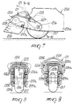
- the reference numeral 1 generally designates a braking device that is particularly usable for skates 2 which comprise a shoe 3 associated with a substantially U-shaped frame 4.
- a plurality of wheels 7 are associated, by means of adapted first pivots 6, between the wings 5 of the frame 4 and are accordingly mutually aligned.
- a support 8 for a brake pad 9, made of plastics, is pivoted to the rear of the frame 4 at the first pivot 6 of the rear wheel 7 or by means of studs that are pivoted to the wings 5 of the frame.
- the support 8 is also provided with two shoulders 10a and 10b, one end whereof is pivoted to the frame 4; the brake pad 9 is associated below the support.
- the braking device comprises means for selectively positioning the support 8 with respect to the frame 4.
- This means is constituted by a lever 11 that has an eccentric head pivoted, by means of a second pivot 12, between the two shoulders 10a and 10b of the support 8, in a region that is intermediate between the ends that are pivoted to the frame 4 and are provided with the brake 9.
- the eccentric head of the lever 11 interacts in contrast with the free end of a bar 13, which is freely and transversely pivoted, at one end, between the two shoulders 10a and 10b of the support 8 by means of an adapted screw 14, which cooperates with a lock nut 15.
- the bar 13 can oscillate with respect to the screw 14 in contrast with a flexible element such as a spring 16 constituted by a metal wire.
- a flexible element such as a spring 16 constituted by a metal wire.
- One end of the spring abuts against a projection 17 that protrudes transversely with respect to the two shoulders 10a and 10b, in the region that lies above the brake 9, and then surrounds the stem of the screw 14 and engages, at its other end, at the bar 13, so as to force its positioning in the direction of said projection 17.
- the free end of the bar 13 is provided with a toothed region 18 that faces a complementarily shaped set of teeth 19 that is formed to the rear of the frame 4.
- the use of the braking device is as follows: after rotatably associating the support 8 with the frame 4, and after positioning the lever 11 in the open condition, as shown in figure 1, the user can position in the desired position the end of the bar 13 that is provided with the toothed region 18 at the desired teeth of the complementarily shaped set of teeth 19 formed on the frame 4.
- This operation can be performed by the user while he is wearing the skate.
- a tab 20 is provided at at least one end of the two shoulders 10a and 10b. Said tab protrudes perimetrically and abuts at an adapted lug 21 that protrudes laterally with respect to a wing 5 of the frame 4.
- the arrangements of the lug 21 and of the tab 20 are such as to allow, for example, to position the brake 9 so that it is slightly raised from the ground 22 when the lever 11 is open and when the support is not being supported by the user.
- the user can therefore vary, according to the wear of the brake 9, the angular position of the support with respect to the frame simply by gripping the lever and can tighten it again, after opening it by, producing one or more ratcheting actions between the toothed region 18 and the complementarily shaped set of teeth 19.
- the projection 17 protrudes towards the frame 4, so that the end of the complementarily shaped set of teeth 19 that faces the ground 22 interacts with it by abutment beyond a given degree of backward rotation imparted to the shoe.
- the user can deactivate the brake 9, locking the support 8 in the position in which the complementarily shaped set of teeth 19 is furthest from the ground.
- the invention has achieved the intended aim and objects, a braking device having been provided in which, even while wearing the skate, it is possible to easily and quickly vary the position of the brake with respect to the ground, accordingly compensating for the wear of the brake pad or allowing to deactivate it.
- the device is also structurally simple and allows the user to brake, despite variation in skate wear, by imparting the same inclination to the shoe.
- figure 6 illustrates a second embodiment of the invention, in which a U-shaped element 123 is likewise pivoted inside the two shoulders at the second pivot 112 for pivoting of the lever 111 to said two shoulders 110.
- said element 123 is provided with a toothed region 118 with which a complementarily shaped set of teeth 119 selectively interacts.
- Said set of teeth 119 is formed on the inside lateral surface of the facing frame 104.
- the second pivot 112 is located at adapted slots formed on the two shoulders 110, so as to allow, when the lever 111 provided with the eccentric head opens and closes, to raise, or in any case move, the element 123 and therefore mutually engage or disengage the toothed region 118 and the complementarily shaped set of teeth 119.
- Figures 7 to 12 illustrate a third embodiment for a skate 202 that comprises a shoe 203 associated with a substantially U-shaped frame 204, and between the wings 205a and 205b of which a plurality of wheels 207 are transversely and rotatably associated by means of adapted first pivots 206 and are therefore mutually aligned.
- a support 208 for a brake 209 is pivoted to the rear of the frame 204 at the first pivot 206 of the rear wheel 207 or by means of studs pivoted to the wings 205 of the frame.
- the support 208 is also provided with two shoulders 210a and 210b, one end whereof is pivoted to the frame 204; the brake 209 is associated with the other end of said shoulders, which are arranged outside the wings 205a and 205b of the frame 204.
- a U-shaped spacer 225 is interposed inside the wings 205a and 205b of the frame 204; the ends of said spacer are pivoted at the same first pivot 206 of said support 208.
- the braking device comprises a means for selectively positioning the support 208 with respect to the frame 204.
- Said means is constituted by a lever 211 that is constituted by a substantially C-shaped metal wire, the base 224 whereof is arranged above the support 208 so as to externally surround it in the opposite direction with respect to the frame 204; the tips 226a and 226b of said wire are flexible by divarication and are folded towards the pair of shoulders 210a and 210b.
- Said tips 226a and 226b can be selectively positioned at a first pair of holes 229a and 229b formed on the two shoulders 210a and 210b of the support 208 and at one of two or more pairs of second holes 227a and 227b formed on said wings 205a and 205b and on said spacer 225.
- the tips 226a and 226b of the lever 211 can be divaricated by means of two raised portions 228a and 228b at the outside lateral surface of the two shoulders 210a and 210b of the support 208; said raised portions have inclined surfaces with which said tips interact when the lever 211 is raised or lowered.
- the tips 226a and 226b disengage the second holes 227a or 227b that affect the spacer 225 and the wings 205a and 205b of the frame 204: this allows to reposition said tips in the other pair of second holes after rotating the support 208.
Landscapes
- Footwear And Its Accessory, Manufacturing Method And Apparatuses (AREA)
- Braking Arrangements (AREA)
Applications Claiming Priority (2)
| Application Number | Priority Date | Filing Date | Title |
|---|---|---|---|
| ITTV940068 | 1994-06-13 | ||
| ITTV940068A IT1273902B (it) | 1994-06-13 | 1994-06-13 | Struttura di dispositivo frenante, particolarmente per pattini ad attivazione migliorata |
Publications (2)
| Publication Number | Publication Date |
|---|---|
| EP0687487A2 true EP0687487A2 (de) | 1995-12-20 |
| EP0687487A3 EP0687487A3 (de) | 1996-03-13 |
Family
ID=11419479
Family Applications (1)
| Application Number | Title | Priority Date | Filing Date |
|---|---|---|---|
| EP95108634A Withdrawn EP0687487A3 (de) | 1994-06-13 | 1995-06-06 | Bremsvorrichtung, insbesondere für Rollschuhe |
Country Status (3)
| Country | Link |
|---|---|
| EP (1) | EP0687487A3 (de) |
| CA (1) | CA2151552A1 (de) |
| IT (1) | IT1273902B (de) |
Cited By (6)
| Publication number | Priority date | Publication date | Assignee | Title |
|---|---|---|---|---|
| FR2747050A1 (fr) * | 1996-04-05 | 1997-10-10 | Salomon Sa | Dispositif de freinage pour patin a roues |
| EP0806229A3 (de) * | 1996-05-10 | 1998-02-11 | Bauer Italia S.p.A. | Einspuriger Rollschuh |
| EP0850669A1 (de) * | 1996-12-31 | 1998-07-01 | Skis Rossignol S.A. | Bremse für Einspurrollschuhe |
| EP0928623A3 (de) * | 1998-01-09 | 2000-04-12 | BENETTON GROUP S.p.A. | Vorrichtung zur Regenerierung einer Bremse, insbesondere für Rollschuhe |
| EP0962238A3 (de) * | 1998-06-01 | 2002-09-04 | Rollerblade, Inc. | Schnelljustierbremsvorrichtung |
| EP1867368A3 (de) * | 2006-06-16 | 2008-10-29 | NORDICA S.p.A. | Rollschuhanordnung mit Bremsvorrichtung |
Citations (1)
| Publication number | Priority date | Publication date | Assignee | Title |
|---|---|---|---|---|
| US5197572A (en) | 1991-04-25 | 1993-03-30 | Roberts Jeffrey A | In-line skate brake system |
Family Cites Families (2)
| Publication number | Priority date | Publication date | Assignee | Title |
|---|---|---|---|---|
| WO1982003334A1 (fr) * | 1981-03-25 | 1982-10-14 | Vladimir Redalie | Patins a roulettes comportant des moyens de blocage des roulettes |
| US5505468A (en) * | 1992-10-23 | 1996-04-09 | Nordica S.P.A. | Braking device particularly for skates |
-
1994
- 1994-06-13 IT ITTV940068A patent/IT1273902B/it active IP Right Grant
-
1995
- 1995-06-06 EP EP95108634A patent/EP0687487A3/de not_active Withdrawn
- 1995-06-12 CA CA002151552A patent/CA2151552A1/en not_active Abandoned
Patent Citations (1)
| Publication number | Priority date | Publication date | Assignee | Title |
|---|---|---|---|---|
| US5197572A (en) | 1991-04-25 | 1993-03-30 | Roberts Jeffrey A | In-line skate brake system |
Cited By (11)
| Publication number | Priority date | Publication date | Assignee | Title |
|---|---|---|---|---|
| US6059297A (en) * | 1993-04-05 | 2000-05-09 | Salomon S.A. | Braking device for roller skates |
| FR2747050A1 (fr) * | 1996-04-05 | 1997-10-10 | Salomon Sa | Dispositif de freinage pour patin a roues |
| WO1997037733A1 (fr) * | 1996-04-05 | 1997-10-16 | Salomon S.A. | Dispositif de freinage pour patin a roues |
| EP0806229A3 (de) * | 1996-05-10 | 1998-02-11 | Bauer Italia S.p.A. | Einspuriger Rollschuh |
| EP0850669A1 (de) * | 1996-12-31 | 1998-07-01 | Skis Rossignol S.A. | Bremse für Einspurrollschuhe |
| FR2757781A1 (fr) * | 1996-12-31 | 1998-07-03 | Rossignol Sa | Frein pour patin a roulettes en ligne |
| US6435525B1 (en) | 1996-12-31 | 2002-08-20 | Skis Rossignol S.A. | Brake for an in-line roller skate |
| EP0928623A3 (de) * | 1998-01-09 | 2000-04-12 | BENETTON GROUP S.p.A. | Vorrichtung zur Regenerierung einer Bremse, insbesondere für Rollschuhe |
| US6199668B1 (en) | 1998-01-09 | 2001-03-13 | Benetton Group S.P.A. | Device for regenerating a brake particularly for skates |
| EP0962238A3 (de) * | 1998-06-01 | 2002-09-04 | Rollerblade, Inc. | Schnelljustierbremsvorrichtung |
| EP1867368A3 (de) * | 2006-06-16 | 2008-10-29 | NORDICA S.p.A. | Rollschuhanordnung mit Bremsvorrichtung |
Also Published As
| Publication number | Publication date |
|---|---|
| ITTV940068A0 (it) | 1994-06-13 |
| ITTV940068A1 (it) | 1995-12-13 |
| EP0687487A3 (de) | 1996-03-13 |
| IT1273902B (it) | 1997-07-11 |
| CA2151552A1 (en) | 1995-12-14 |
Similar Documents
| Publication | Publication Date | Title |
|---|---|---|
| US5755449A (en) | In-line skate | |
| EP0594080B1 (de) | Bremsvorrichtung insbesondere für Rollschuhe | |
| US5505469A (en) | Braking device particularly for skates | |
| EP0567948B1 (de) | Bremsvorrichtung an Rollschuh | |
| US4807893A (en) | Roller skate | |
| EP0599043B1 (de) | Bremsvorrichtung an Rollschuh | |
| JPH06225958A (ja) | スケート靴 | |
| US5527048A (en) | Braking device particularly for skates with aligned wheels | |
| CA2154399A1 (en) | In-line roller blade braking device | |
| EP0545250A2 (de) | Bremsvorrichtung, besonder für einspurige Rollschuhe | |
| CA2151552A1 (en) | Braking device particularly for roller skates | |
| EP0815906B1 (de) | Rollschuh mit Bremskontrolleinrichtung | |
| EP0681857B1 (de) | Bremseinrichtung, insbesondere für Rollschuhe | |
| EP0685245B1 (de) | Rollschuh mit Bremsvorrichtung | |
| US6666462B2 (en) | Brake for inline skates | |
| EP0681856B1 (de) | Rollschuh mit einer Bremsvorrichtung | |
| EP0974380B1 (de) | Rollschuh mit einer Bremsvorrichtung | |
| EP0928623A2 (de) | Vorrichtung zur Regenerierung einer Bremse, insbesondere für Rollschuhe | |
| US6007076A (en) | Braking device particularly for skates | |
| EP0806229A2 (de) | Einspuriger Rollschuh |
Legal Events
| Date | Code | Title | Description |
|---|---|---|---|
| PUAI | Public reference made under article 153(3) epc to a published international application that has entered the european phase |
Free format text: ORIGINAL CODE: 0009012 |
|
| AK | Designated contracting states |
Kind code of ref document: A2 Designated state(s): AT CH DE ES FR IT LI |
|
| PUAL | Search report despatched |
Free format text: ORIGINAL CODE: 0009013 |
|
| AK | Designated contracting states |
Kind code of ref document: A3 Designated state(s): AT CH DE ES FR IT LI |
|
| STAA | Information on the status of an ep patent application or granted ep patent |
Free format text: STATUS: THE APPLICATION HAS BEEN WITHDRAWN |
|
| 18W | Application withdrawn |
Withdrawal date: 19960508 |