EP0806229A2 - Einspuriger Rollschuh - Google Patents
Einspuriger Rollschuh Download PDFInfo
- Publication number
- EP0806229A2 EP0806229A2 EP97201409A EP97201409A EP0806229A2 EP 0806229 A2 EP0806229 A2 EP 0806229A2 EP 97201409 A EP97201409 A EP 97201409A EP 97201409 A EP97201409 A EP 97201409A EP 0806229 A2 EP0806229 A2 EP 0806229A2
- Authority
- EP
- European Patent Office
- Prior art keywords
- frame
- arm
- strut
- skate
- pad
- Prior art date
- Legal status (The legal status is an assumption and is not a legal conclusion. Google has not performed a legal analysis and makes no representation as to the accuracy of the status listed.)
- Withdrawn
Links
Images

Classifications
-
- A—HUMAN NECESSITIES
- A63—SPORTS; GAMES; AMUSEMENTS
- A63C—SKATES; SKIS; ROLLER SKATES; DESIGN OR LAYOUT OF COURTS, RINKS OR THE LIKE
- A63C17/00—Roller skates; Skate-boards
- A63C17/14—Roller skates; Skate-boards with brakes, e.g. toe stoppers, freewheel roller clutches
- A63C17/1436—Roller skates; Skate-boards with brakes, e.g. toe stoppers, freewheel roller clutches contacting the ground
-
- A—HUMAN NECESSITIES
- A63—SPORTS; GAMES; AMUSEMENTS
- A63C—SKATES; SKIS; ROLLER SKATES; DESIGN OR LAYOUT OF COURTS, RINKS OR THE LIKE
- A63C17/00—Roller skates; Skate-boards
- A63C17/04—Roller skates; Skate-boards with wheels arranged otherwise than in two pairs
- A63C17/06—Roller skates; Skate-boards with wheels arranged otherwise than in two pairs single-track type
Definitions
- the present invention relates to an in-line roller skate comprising a frame for supporting the wheels and a pad brake including a pad-support arm articulated to the frame and a strut for adjusting the pivoting of the arm relative to the frame.
- Skates are known in the art, which are equipped with a rubber pad fitted on an arm mounted on the rear of the wheel-support frame so that, if the toe of the skate is raised, the pad is pressed against the ground and a braking action for slowing the skater's movement is consequently exerted owing to friction between the pad and the ground.
- the pad-support arm is usually articulated to the wheel-support frame, for example, about the axis of the rear wheel, and its pivoting is adjusted by a strut having opposite ends articulated, respectively, to the brake arm and to a portion of the cuff or of the shell of the skate.
- the reaction load on the pad resulting from the pressure exerted on the ground during braking thus acts on the cuff or shell portion, through the strut.
- the problem upon which the present invention is based is that of providing a skate which is structurally and functionally designed so as to overcome all of the problems complained of with reference to the prior art mentioned.
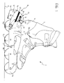
- an in-line roller skate generally indicated 1 has an elongate wheel-support frame 2; the frame 2 includes two parallel sides 3, 4 between which four aligned wheels 5a-d with parallel axes are supported for rotation.
- a shell 6 is fixed to the frame 2 on the opposite side to the wheels 5a-d.
- a cuff 7 is articulated to the shell 6 by means of pins 6a.
- the skate 1 is equipped with a brake 8 comprising an arm 9 supporting a pad 10 which is intended to be pressed against the ground during the braking of the skate.
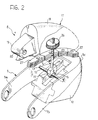
- the pad-support arm 9 is substantially U-shaped with two legs 9a, 9b disposed side by side and connected to one another at one end by a curved wall 9c. Each leg 9a, 9b is articulated to the wheel-support frame 2 by its free end, about the axis of the wheel 5d.
- the pad 10 is held on the arm 9 in the region of the juxtaposed edges of the legs 9a, 9b, close to the wall 9c which connects them.
- a pin, indicated 12 has opposite ends fitted in the legs 9a, 9b, respectively, at the same predetermined distance from the pivot axis of the arm 9.
- the brake 8 also comprises a strut 13 including a shaft 14 threaded at one end and carrying, at its opposite end, a head 15 in which a slot 16, which is elongate transverse the axis of the shaft 14, is formed.
- the strut 13 is connected to the frame 2 by means of an anchoring element, generally indicated 17 and including a block 18 from which an integral appendage 19 extends.
- the appendage 19 has a first through-hole 20 and is housed in the frame 2 through a hole 21 thereof.
- Each side 3, 4 has a respective second through-hole 22, 23 formed in a position such as to be aligned with the first hole 20 when the block 18 is in abutment with the frame 2 and the appendage 19 is housed inside it, for the fixing of the anchoring element 17 to the frame 2 by means of a screw, not shown.
- anchoring element 17, the strut 13 and the pad-support arm 9 constitute an individually manipulable unit for the brake 8, the mounting of which on the skate requires merely the provision of the hole 21 and of the holes 22, 23 in the wheel-support frame 2.
- the block 18 has a through-hole 24 and a third hole 25 intersecting the hole 24 perpendicularly.
- the hole 24 constitutes a seat for housing a ring nut 16 engaged for screwing on the shaft 14 which in turn is housed and guided for sliding in the hole 25.
- the shape of the block 18 in the region of the hole 24 is such that the ring nut 26, which has a knurled outer surface for facilitating gripping thereof, is accessible from outside the anchoring element 17.
- Extensible bellows-like elements are interposed between the block 18 and the arm 9.
- Screwing of the ring nut 26 on the shaft 14 causes the strut 13 to slide axially relative to the block 18 and causes the pad-support arm 9 simultaneously to pivot about its axis of articulation to the frame 2.
- the distance of the pad 10 from the ground can thus be adjusted according to the skater's specific requirements, for example, in order to advance or delay the braking action resulting from the upward pivoting of the toe of the skate during braking, or simply to compensate for progressive wear of the pad.
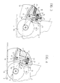
- Figure 3 shows the brake 8 in a first adjustment position in which the pad 10 has pivoted relative to the frame 2 to the maximum distance from the ground, identified by a reference plane P. In this position, the threaded portion of the shaft 14 is housed inside the hole 25.
- the arm 9 is pivoted anticlockwise with reference to the drawing of Figure 3 by rotation of the ring nut 26 in the sense in which the shaft 14 is unscrewed from the ring nut and the distance of the pad 10 from the plane P is consequently reduced until the minimum distance of the pad 10 from the ground is reached ( Figure 4).
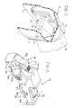
- an in-line roller skate generally indicated 100, comprises a frame 102 carrying parallel sides 103, 104 between which aligned wheels 105a-d with parallel axes are supported for rotating.
- the skate 100 is equipped with a brake 108 including an arm 109 for supporting a pad 110.
- the arm 109 is U-shaped with opposed legs 109a, 109b disposed side by side and articulated to the frame 102 at their free ends about the axis of the wheel 105d.
- the brake 108 also comprises a strut, generally indicated 113, extending between the arm 109 and the wheel-support frame 102, as will be explained in detail below.
- the strut 113 comprises a substantially L-shaped member 111 with two limbs 111a, 111b.
- the member 111 can pivot on the arm 109 at the free end of the limb 111a by means of a pin 112, whereas the free end of the limb 111b is housed in the frame 102 through a first hole 121 formed in the frame.
- a second through-hole 124 is formed in the limb 111b of the member, outside the frame 102, and is intersected transversely by a blind hole 125 extending in the limb 111b from the free end thereof.
- a threaded shaft 114 is housed and guided for sliding in the hole 125 by one of its end portions and, at its opposite end, is pivotable on the frame 102 by means of a pin 129 interposed between the sides 103, 104.
- the second hole 124 forms a seat for housing a ring nut 126 engaged for screwing on the shaft 114 and accessible from outside the frame 102.
- the brake 108 is shown in an intermediate adjustment position between the positions of minimum and maximum angular pivoting of the arm 109 relative to the frame 102. It will be noted that, in this position, the pad-support arm 109 is locked relative to the frame by means of the strut 113.
- the distance between the points of articulation of the strut 113 to the arm 109 and to the frame 102, respectively, is indicated C in Figure 8.
- the distances between the axis of the wheel 105d and the axis of the pin 112 and between the axis of the wheel 105d and the axis of the pin 129 are also shown in the same drawing, indicated A and B, respectively; these distances A, B are fixed and determined at the stage when the skate is designed.
- Rotation of the ring nut 126 causes the shaft 114 to slide relative to the member 111 so as to vary the distance C and bring about simultaneous pivoting of the arm 109 relative to the frame 102.
- the pad 110 is thus pivoted to a preselected angular position relative to the frame, corresponding to the desired distance of the pad from the ground.
- the brake 108 is also individually manipulable and its mounting on the skate 100 merely requires drilling of the frame 102 to provide the hole 121 and the holes for the fixing of the pin 129.
- the compactness of the brake is arranged for fixing to the wheel-support frame avoids the provision of specific attachments for the adjustment strut on the cuff, thus achieving a structural simplification of the cuff and of its mould, if it is moulded from plastics material.
Landscapes
- Footwear And Its Accessory, Manufacturing Method And Apparatuses (AREA)
- Braking Arrangements (AREA)
Applications Claiming Priority (2)
| Application Number | Priority Date | Filing Date | Title |
|---|---|---|---|
| ITPD960118 | 1996-05-10 | ||
| IT96PD000118A IT1287897B1 (it) | 1996-05-10 | 1996-05-10 | Pattino del tipo a ruote in linea |
Publications (2)
| Publication Number | Publication Date |
|---|---|
| EP0806229A2 true EP0806229A2 (de) | 1997-11-12 |
| EP0806229A3 EP0806229A3 (de) | 1998-02-11 |
Family
ID=11391421
Family Applications (1)
| Application Number | Title | Priority Date | Filing Date |
|---|---|---|---|
| EP97201409A Withdrawn EP0806229A3 (de) | 1996-05-10 | 1997-05-09 | Einspuriger Rollschuh |
Country Status (4)
| Country | Link |
|---|---|
| EP (1) | EP0806229A3 (de) |
| JP (1) | JPH1066745A (de) |
| CA (1) | CA2204982A1 (de) |
| IT (1) | IT1287897B1 (de) |
Cited By (1)
| Publication number | Priority date | Publication date | Assignee | Title |
|---|---|---|---|---|
| EP1867368A3 (de) * | 2006-06-16 | 2008-10-29 | NORDICA S.p.A. | Rollschuhanordnung mit Bremsvorrichtung |
Family Cites Families (2)
| Publication number | Priority date | Publication date | Assignee | Title |
|---|---|---|---|---|
| US5275259A (en) * | 1991-04-25 | 1994-01-04 | Jeff Roberts | In-line skate brake system |
| IT1273902B (it) * | 1994-06-13 | 1997-07-11 | Nordica Spa | Struttura di dispositivo frenante, particolarmente per pattini ad attivazione migliorata |
-
1996
- 1996-05-10 IT IT96PD000118A patent/IT1287897B1/it active IP Right Grant
-
1997
- 1997-05-09 JP JP9119963A patent/JPH1066745A/ja active Pending
- 1997-05-09 EP EP97201409A patent/EP0806229A3/de not_active Withdrawn
- 1997-05-09 CA CA002204982A patent/CA2204982A1/en not_active Abandoned
Cited By (1)
| Publication number | Priority date | Publication date | Assignee | Title |
|---|---|---|---|---|
| EP1867368A3 (de) * | 2006-06-16 | 2008-10-29 | NORDICA S.p.A. | Rollschuhanordnung mit Bremsvorrichtung |
Also Published As
| Publication number | Publication date |
|---|---|
| ITPD960118A1 (it) | 1997-11-10 |
| CA2204982A1 (en) | 1997-11-10 |
| ITPD960118A0 (it) | 1996-05-10 |
| EP0806229A3 (de) | 1998-02-11 |
| JPH1066745A (ja) | 1998-03-10 |
| IT1287897B1 (it) | 1998-08-26 |
Similar Documents
| Publication | Publication Date | Title |
|---|---|---|
| US5486011A (en) | Spring biased braking device for in-line roller skates | |
| CA2095075C (en) | Braking device, particularly for skates | |
| US5403021A (en) | Brake assembly for in-line roller skates | |
| US4470175A (en) | Fastening device for ski-boots | |
| EP0594080B1 (de) | Bremsvorrichtung insbesondere für Rollschuhe | |
| US5501474A (en) | Braking device for in-line skates | |
| CA2135364A1 (en) | In-line skate | |
| JP2786392B2 (ja) | ブレーキ装置 | |
| EP0944416A1 (de) | Einspurrollschuh für extrem-skating | |
| EP0379906A2 (de) | Rollschuhe mit Bremsvorrichtung | |
| US5775705A (en) | Convertible in-line/parallel skates | |
| EP0599043A2 (de) | Bremsvorrichtung an Rollschuh | |
| US3608919A (en) | Ski boot and ski binding therefor | |
| US5522609A (en) | Adjustable skate brake | |
| CA2083339A1 (en) | Braking device, particularly for skates with aligned wheels | |
| JPS62243573A (ja) | スキ−の安全固定装置 | |
| US6598887B2 (en) | In-line roller skates with braking device | |
| US5735537A (en) | Braking device particularly for skates | |
| CA2204982A1 (en) | An in-line roller skate | |
| EP0685245B1 (de) | Rollschuh mit Bremsvorrichtung | |
| EP0656221A1 (de) | Bremsvorrichtung, insbesondere für Rollschuhe | |
| EP0687487A2 (de) | Bremsvorrichtung, insbesondere für Rollschuhe | |
| US2033334A (en) | Safety roller skate | |
| US20060097465A1 (en) | Four wheel mechanical brake system for inline skates | |
| USRE33388E (en) | Toe piece for a safety ski-binding |
Legal Events
| Date | Code | Title | Description |
|---|---|---|---|
| PUAI | Public reference made under article 153(3) epc to a published international application that has entered the european phase |
Free format text: ORIGINAL CODE: 0009012 |
|
| AK | Designated contracting states |
Kind code of ref document: A2 Designated state(s): AT BE CH DE DK ES FI FR GB GR IE IT LI LU NL PT SE |
|
| PUAL | Search report despatched |
Free format text: ORIGINAL CODE: 0009013 |
|
| RHK1 | Main classification (correction) |
Ipc: A63C 17/14 |
|
| AK | Designated contracting states |
Kind code of ref document: A3 Designated state(s): AT BE CH DE DK ES FI FR GB GR IE IT LI LU MC NL PT SE |
|
| RBV | Designated contracting states (corrected) |
Designated state(s): AT BE CH DE DK ES FI FR GB GR IE IT LI LU NL PT SE |
|
| 17P | Request for examination filed |
Effective date: 19980417 |
|
| STAA | Information on the status of an ep patent application or granted ep patent |
Free format text: STATUS: THE APPLICATION HAS BEEN WITHDRAWN |
|
| 18W | Application withdrawn |
Withdrawal date: 19990514 |