EP0687560A1 - Präzisionsdruckmaschine, insbesondere für Gewebe oder dergleichen, mit mehreren Druckstationen - Google Patents
Präzisionsdruckmaschine, insbesondere für Gewebe oder dergleichen, mit mehreren Druckstationen Download PDFInfo
- Publication number
- EP0687560A1 EP0687560A1 EP95107148A EP95107148A EP0687560A1 EP 0687560 A1 EP0687560 A1 EP 0687560A1 EP 95107148 A EP95107148 A EP 95107148A EP 95107148 A EP95107148 A EP 95107148A EP 0687560 A1 EP0687560 A1 EP 0687560A1
- Authority
- EP
- European Patent Office
- Prior art keywords
- printing
- supporting element
- belt
- printing station
- stations
- Prior art date
- Legal status (The legal status is an assumption and is not a legal conclusion. Google has not performed a legal analysis and makes no representation as to the accuracy of the status listed.)
- Withdrawn
Links
- 239000004744 fabric Substances 0.000 title claims abstract description 26
- 238000001514 detection method Methods 0.000 claims abstract description 8
- 238000000034 method Methods 0.000 claims description 3
- 230000008878 coupling Effects 0.000 claims description 2
- 238000010168 coupling process Methods 0.000 claims description 2
- 238000005859 coupling reaction Methods 0.000 claims description 2
- 230000003287 optical effect Effects 0.000 claims description 2
- 230000009471 action Effects 0.000 description 2
- 230000008901 benefit Effects 0.000 description 2
- 239000003086 colorant Substances 0.000 description 2
- 239000000463 material Substances 0.000 description 2
- 238000010586 diagram Methods 0.000 description 1
- 230000000670 limiting effect Effects 0.000 description 1
- 230000004048 modification Effects 0.000 description 1
- 238000012986 modification Methods 0.000 description 1
- 230000008569 process Effects 0.000 description 1
- 238000004080 punching Methods 0.000 description 1
- 238000004904 shortening Methods 0.000 description 1
Images

Classifications
-
- B—PERFORMING OPERATIONS; TRANSPORTING
- B41—PRINTING; LINING MACHINES; TYPEWRITERS; STAMPS
- B41F—PRINTING MACHINES OR PRESSES
- B41F15/00—Screen printers
- B41F15/08—Machines
- B41F15/10—Machines for multicolour printing
-
- B—PERFORMING OPERATIONS; TRANSPORTING
- B41—PRINTING; LINING MACHINES; TYPEWRITERS; STAMPS
- B41F—PRINTING MACHINES OR PRESSES
- B41F17/00—Printing apparatus or machines of special types or for particular purposes, not otherwise provided for
- B41F17/003—Special types of machines for printing textiles
- B41F17/005—Supports for workpieces; Devices for securing the workpieces to the supports
Definitions
- the present invention relates to a printing machine, particularly for fabrics and the like, with multiple printing stations.
- the multiple color pattern is produced by means of successive printing operations, applying a single color in each printing station.
- One of the main problems of printing performed with these machines is the correct execution of the printing operations carried out in the stations that follow the first one.
- the printing operation performed in the subsequent stations must be positioned perfectly on the fabric with respect to the printing operations performed in the previous stations, so that unwanted overlaps or gaps between the variously colored regions of the pattern to be produced do not occur.
- control devices that cause the supporting element to advance by strictly identical successive steps.
- Such devices are generally constituted by readers that monitor the rotation of the driving rollers of the belt-like supporting element, or by readers that detect the advancement of the supporting element, correcting, if necessary, the action of the motor on the driving rollers.
- readers that monitor the rotation of the driving rollers of the belt-like supporting element, or by readers that detect the advancement of the supporting element, correcting, if necessary, the action of the motor on the driving rollers.
- particular care is taken in rigidly coupling the fabric to the belt-like supporting element.
- the various printing stations are furthermore mounted on a supporting framework so that they can be adjusted in the direction along which the belt-like supporting element advances, so as to allow to correct their position before the printing process begins.
- An aim of the present invention is to solve the problems described above by providing a printing machine, particularly for fabrics or the like, that is capable of ensuring high printing precision even in case of accidental variations in the length of the belt-like supporting element.
- an object of the invention is to provide a printing machine that does not require continuous manual interventions for adjusting the position of the printing stations.
- Another object of the invention is to provide a printing machine that ensures high productivity.
- a printing machine particularly for fabrics or the like, with multiple printing stations, comprising: a belt-like supporting element, controllably movable along an advancement direction, for the fabric or the like to be printed; a first printing station and at least one second printing station that are mutually spaced along said advancement direction; characterized in that it comprises registration means located on said belt-like supporting element and means for detecting said registration means which are associated with said printing stations; said at least one second printing station being controllably movable along said advancement direction so as to position itself with respect to said belt-like supporting element according to the detection of said registration means on the part of said detector means so as to produce, on the fabric, a print in a preset position with respect to the print produced by said first printing station.
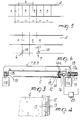
- the printing machine generally designated by the reference numeral 1, comprises in a per se known manner a belt-like supporting element 2 controllably movable along an advancement direction 3 and on which the fabric 4 or the like to be printed is arranged and rigidly coupled.
- the belt-like supporting element 2 can wind, as in conventional printing machines, around two rollers 5a and 5b with mutually parallel horizontal axes, at least one of which is driven so as to turn intermittently by steps of a preset extent, so as to cause an intermittent advancement of the belt-like supporting element 2.
- a first printing station 6 and at least one second printing station 7 are arranged along the extension of the belt-like supporting element 2 and are mutually spaced along the advancement direction 3.
- printing stations 6 to 9 are arranged along the extension of the belt-like supporting element 2.
- the printing machine comprises registration means located on the belt-like supporting element 2 and means for detecting said registration means which are associated with the printing stations 6 to 9.
- At least the printing stations after the first one that is to say, the printing stations 7, 8, and 9 shown in the drawings, are controllably movable along the advancement direction 3, in one direction or the other, so as to arrange themselves with respect to the belt-like supporting element 2 according to the detection of the registration means, performed by the detector means, so as to produce, on the fabric 4, a print in a preset position with respect to the print formed by the first printing station 6.
- the printing stations 7, 8, and 9 comprise a supporting framework 10 that rests slidingly on guides 11a and 11b laterally arranged on opposite sides with respect to the belt-like supporting element 2 and running parallely to the advancement direction 3.
- the first printing station 6 can also be mounted on the guides 11a and 11b and is preferably fixed to said guides 11a and 11b, that is to say, so that it cannot slide after a first adjustment positioning.
- the registration means according to the invention are conveniently constituted, in the illustrated embodiment, by a band 12 that is fixed to a perimetric side of the belt-like supporting element 2 which is parallel to the advancement direction 3. Said band 12 is provided with notches or holes 13 uniformly mutually spaced along the advancement direction 3.
- the detector means according to the invention preferably comprise, as shown, a wheel 14 with teeth 14a that mesh with the notches or holes 13.
- the framework 10 of the corresponding printing station supports said wheel so that it can rotate about its own axis 15, which is arranged transversely to the advancement direction 3.
- a detector element 16 is arranged on the shaft of each wheel 14 and is preferably constituted by an encoder that detects the rotation of the wheel 14 about its axis 15.
- Each one of the printing stations that is movable along the guides 11a and 11b that is to say, each one of the printing stations 7, 8, and 9, is provided with a driving element 17, for example an electric motor, the output shaft 17a whereof is connected to a pinion 18 that meshes with a rack 19 rigidly coupled to the guides 11a and 11b and running parallely to the advancement direction 3.
- a driving element 17 for example an electric motor
- the output shaft 17a whereof is connected to a pinion 18 that meshes with a rack 19 rigidly coupled to the guides 11a and 11b and running parallely to the advancement direction 3.
- the first printing station 6, too, can be provided with an electric motor 27, the output shaft whereof is connected to a pinion that meshes with the rack 19.
- the actuation of the motor 27 of the first printing station 6 is not controlled by the detection performed by the detector means but is caused simply by the need to adjust the position of the first printing station 6 along the guides 11a and 11b when printing begins.
- the rack 19 can be directly embedded in one of the guides 11a and 11b, and it is also possible to provide a rack for each one of the guides 11a and 11b and two pinions 18, at least one of which is motorized, so as to achieve perfect travel of the framework 10 of each one of the printing stations along the advancement direction 3.
- the rack 19 might also be omitted and the movement of the printing stations 6 to 9 might be achieved by means of a toothless wheel, instead of the pinion 18, which rests directly on one of the guides 11a and 11b, since any slippage of said wheel does not produce errors in the positioning of the printing stations 6 to 9 with respect to the belt-like supporting element 2, since this positioning is controlled by the detector means.
- the various detector elements 16 of the printing stations 6, 7, 8, and 9 are connected to the input of an electronic control unit 20 that supervises the operation of the printing machine.
- the output of this electronic control unit 20 is connected to the motors 17 of the various printing stations so as to actuate said motors according to the detection performed by the various detector elements 16 of the printing stations, as will become apparent hereinafter.
- the registration means can furthermore be formed directly on the belt-like supporting element 2.
- the registration means instead of being provided beforehand on the belt-like supporting element or on a metallic or magnetic band associated with the belt-like supporting element 2, can be "placed" by a device that is associated with the first printing station and can be activated during the printing operation performed in said station 6.
- Said device can be constituted by an additional printing device for applying optically detectable register marks, or by a punching device for applying mechanically detectable register marks, or by a magnetic recording head for applying, on the magnetic tape associated with the belt-like supporting element 2, register marks that can be detected by a magnetic reader, depending on the detection means to be used.
- the printing stations 6, 7, 8, and 9 When it is necessary to print a fabric with patterns A having a step "r", the printing stations 6, 7, 8, and 9 must be mutually spaced with a center distance "s" that is a multiple of the printing step "r", assuming of course that the length of the belt-like supporting element 2 is unchangeable.
- the belt-like supporting element 2 is actuated so as to place a first region A of the fabric at the first printing station 6.
- the various detectors 16 located on the various printing stations 6, 7, 8, and 9 undergo a sort of reset.
- the belt-like supporting element 2 is moved forward by a step "r", so as to place a second region A to be printed at the first printing station 6; this operation is repeated until the first portion of printed fabric arrives near the second printing station 7.
- the printing stations are mutually spaced by an extent "s" that is equal to twice the printing step "r"
- the detector 16 located in the first printing station 6 has detected a travel of the belt-like supporting element 2 that is equal to 2r, and the detector 16 located in the second printing station 7 should also have detected a travel equal to 2r.
- the two readings, performed respectively by the detector 16 located in the second printing station 7 and by the detector 16 located in the first printing station 6, are sent to the electronic control unit 20 and are compared with each other. If the two read values are identical, while the first printing station 6 performs the third printing stroke the second printing station 7 performs its first printing stroke.
- the electronic control unit 20 activates the motor 17 of the second printing station 7 in one direction or the other, so as to increase or decrease the value read by the detector 16 of the second printing station, in order to make it equal to the value read by the detector of the first printing station.
- the second printing station 7 is activated and accordingly performs its first printing stroke. In this manner the print produced by the second printing station 7 is certainly correctly positioned with respect to the print produced by the first printing station 6.
- the value read by the various detectors 16 located on the stations after the second one is then compared, as already described with reference to the second printing station 7, with the value read by the first printing station 6, so that the prints produced by the other subsequent printing stations are also correctly positioned with respect to the print produced by the first printing station 6 and are thus mutually correctly positioned.
- the printing machine according to the invention fully achieves the intended aim since, by virtue of the fact that it is possible to automatically position the printing stations with respect to the prints produced by previous printing stations, said machine is capable of ensuring high printing precision even in case of accidental variations in the length of the belt-like supporting element.
- Another advantage of the printing machine according to the invention is that it avoids continuous manual adjustments that would entail machine stops, thus ensuring high productivity.
Landscapes
- Engineering & Computer Science (AREA)
- Mechanical Engineering (AREA)
- Textile Engineering (AREA)
- Screen Printers (AREA)
- Coloring (AREA)
- Treatment Of Fiber Materials (AREA)
- Treatments For Attaching Organic Compounds To Fibrous Goods (AREA)
Applications Claiming Priority (2)
| Application Number | Priority Date | Filing Date | Title |
|---|---|---|---|
| ITMI941019A IT1269800B (it) | 1994-05-19 | 1994-05-19 | Macchina da stampa,particolarmente per tessuti o simili,a piu' stazioni di stampa ad elevata precisione |
| ITMI941019 | 1994-05-19 |
Publications (1)
| Publication Number | Publication Date |
|---|---|
| EP0687560A1 true EP0687560A1 (de) | 1995-12-20 |
Family
ID=11368943
Family Applications (1)
| Application Number | Title | Priority Date | Filing Date |
|---|---|---|---|
| EP95107148A Withdrawn EP0687560A1 (de) | 1994-05-19 | 1995-05-11 | Präzisionsdruckmaschine, insbesondere für Gewebe oder dergleichen, mit mehreren Druckstationen |
Country Status (2)
| Country | Link |
|---|---|
| EP (1) | EP0687560A1 (de) |
| IT (1) | IT1269800B (de) |
Cited By (3)
| Publication number | Priority date | Publication date | Assignee | Title |
|---|---|---|---|---|
| EP0727310A1 (de) * | 1995-02-14 | 1996-08-21 | Viero S.R.L. | Vorrichtung zum Bedrucken von Geweben und dergleichen |
| WO2003101737A1 (en) * | 2002-06-04 | 2003-12-11 | Tricksy S.R.L. | Screen printing machine having a replaceable ink jet printing unit |
| EP2759409A1 (de) * | 2013-01-25 | 2014-07-30 | Seiko Epson Corporation | Aufzeichnungsvorrichtung und Aufzeichnungsverfahren |
Citations (6)
| Publication number | Priority date | Publication date | Assignee | Title |
|---|---|---|---|---|
| US4084505A (en) * | 1976-06-14 | 1978-04-18 | Shiro Ichinose | Device for adjusting phase of flat screen |
| FR2397943A1 (fr) * | 1977-07-19 | 1979-02-16 | Reggiani Spa | Procede d'impression polychrome en continu de tissu-eponge, tissus elastifies ou analogues et installation pour la mise en oeuvre de ce procede |
| JPS60179256A (ja) * | 1984-02-27 | 1985-09-13 | Tsuji Senshoku Kk | フラツトスクリ−ン捺染機 |
| EP0242846A2 (de) * | 1986-04-23 | 1987-10-28 | MS MACCHINE E SISTEMI S.r.l. | Rahmendruckmaschine für Textilien oder ähnliches |
| EP0364424A2 (de) * | 1988-10-10 | 1990-04-18 | Svecia Silkscreen Maskiner AB | Verfahren zum Einstellen eines Aufdrucks in einer entsprechenden Druckstellung in Mehrfarbensiebdruckmaschinen |
| JPH068395A (ja) * | 1992-06-25 | 1994-01-18 | Toshin Kogyo Kk | 連続多色印刷方法及び装置 |
-
1994
- 1994-05-19 IT ITMI941019A patent/IT1269800B/it active IP Right Grant
-
1995
- 1995-05-11 EP EP95107148A patent/EP0687560A1/de not_active Withdrawn
Patent Citations (6)
| Publication number | Priority date | Publication date | Assignee | Title |
|---|---|---|---|---|
| US4084505A (en) * | 1976-06-14 | 1978-04-18 | Shiro Ichinose | Device for adjusting phase of flat screen |
| FR2397943A1 (fr) * | 1977-07-19 | 1979-02-16 | Reggiani Spa | Procede d'impression polychrome en continu de tissu-eponge, tissus elastifies ou analogues et installation pour la mise en oeuvre de ce procede |
| JPS60179256A (ja) * | 1984-02-27 | 1985-09-13 | Tsuji Senshoku Kk | フラツトスクリ−ン捺染機 |
| EP0242846A2 (de) * | 1986-04-23 | 1987-10-28 | MS MACCHINE E SISTEMI S.r.l. | Rahmendruckmaschine für Textilien oder ähnliches |
| EP0364424A2 (de) * | 1988-10-10 | 1990-04-18 | Svecia Silkscreen Maskiner AB | Verfahren zum Einstellen eines Aufdrucks in einer entsprechenden Druckstellung in Mehrfarbensiebdruckmaschinen |
| JPH068395A (ja) * | 1992-06-25 | 1994-01-18 | Toshin Kogyo Kk | 連続多色印刷方法及び装置 |
Non-Patent Citations (2)
| Title |
|---|
| PATENT ABSTRACTS OF JAPAN vol. 10, no. 21 (M - 449) 28 January 1986 (1986-01-28) * |
| PATENT ABSTRACTS OF JAPAN vol. 18, no. 206 (M - 1591) 12 April 1994 (1994-04-12) * |
Cited By (6)
| Publication number | Priority date | Publication date | Assignee | Title |
|---|---|---|---|---|
| EP0727310A1 (de) * | 1995-02-14 | 1996-08-21 | Viero S.R.L. | Vorrichtung zum Bedrucken von Geweben und dergleichen |
| WO2003101737A1 (en) * | 2002-06-04 | 2003-12-11 | Tricksy S.R.L. | Screen printing machine having a replaceable ink jet printing unit |
| CN100382961C (zh) * | 2002-06-04 | 2008-04-23 | 屈克西有限公司 | 将一种或多种物质施加到一承印物上的台、机器以及方法 |
| EP2759409A1 (de) * | 2013-01-25 | 2014-07-30 | Seiko Epson Corporation | Aufzeichnungsvorrichtung und Aufzeichnungsverfahren |
| JP2014159152A (ja) * | 2013-01-25 | 2014-09-04 | Seiko Epson Corp | 記録装置及び記録方法 |
| US9090423B2 (en) | 2013-01-25 | 2015-07-28 | Seiko Epson Corporation | Recording apparatus and recording method |
Also Published As
| Publication number | Publication date |
|---|---|
| IT1269800B (it) | 1997-04-15 |
| ITMI941019A1 (it) | 1995-11-19 |
| ITMI941019A0 (it) | 1994-05-19 |
Similar Documents
| Publication | Publication Date | Title |
|---|---|---|
| US5825374A (en) | Apparatus and method for advancing a web | |
| DE69310765T2 (de) | Drucker mit Druckregelvorrichtung | |
| CN103481644A (zh) | 一种具有套印自对准功能的丝网印刷机 | |
| US5777878A (en) | Screen printing press having longitudinal, lateral and angular screen frame registration system and method | |
| EP0820863B1 (de) | Vorrichtung zum Greifen und zur Registriereinstellung eines Werkstückes in einer Siebdruckmaschine | |
| KR20090017585A (ko) | 노광 방법 및 노광 장치 | |
| US3848528A (en) | Multi-station printing system | |
| US3898002A (en) | Method and apparatus for editing a film strip | |
| EP0623451A1 (de) | Verfahren zum Auflegen eines gummierten Textilgewebestreifens auf einer Reifenaufbautrommel und Vorrichtung für die Durchführung des Verfahrens | |
| CN203496423U (zh) | 一种具有套印自对准功能的丝网印刷机 | |
| EP0443771A2 (de) | Verfahren und Vorrichtung zur Positionskorrektur des geschnittenen Randes | |
| EP0474268A1 (de) | Verfahren und Vorrichtung zum Einrichten der Schablonen in eine automatische Siebdruckmaschine | |
| US11345139B2 (en) | System for registering the printing units of a rotary printing machine with manually-adjustable print register | |
| US3253489A (en) | Edge control for splicing | |
| JP3747769B2 (ja) | 電子回路部品の打ち抜き装置及びそのテープ頭出し方法 | |
| US4242957A (en) | Process and apparatus for the printing of sponge-cloths and the like | |
| KR19990037811A (ko) | 라벨자동절단장치 | |
| KR101968473B1 (ko) | 고속 타발기의 타발용 소재 이물질 선별장치 | |
| DE2350460A1 (de) | Automatischer zeichendrucker | |
| ITMI941019A1 (it) | Macchina da stampa, particolarmente per tessuti o simili, a piu' stazioni di stampa ad elevata precisione | |
| EP0309023A2 (de) | Vorrichtung zum Regeln des Schrittes von intermittierend arbeitenden Maschinen, insbesondere selbsttätige Siebdruckmaschinen | |
| CA2042501A1 (en) | Method and apparatus for providing edge-side tracks of holes at a printing belt for rotary printing machines | |
| EP0242846B1 (de) | Rahmendruckmaschine für Textilien oder ähnliches | |
| JPH06238772A (ja) | オートスプライス装置 | |
| DE69612356T2 (de) | Vorrichtung zum Herstellen von graphischen Artikeln mit kalibriertem Druckkopf und Verfahren zu dessen Kalibrierung |
Legal Events
| Date | Code | Title | Description |
|---|---|---|---|
| PUAI | Public reference made under article 153(3) epc to a published international application that has entered the european phase |
Free format text: ORIGINAL CODE: 0009012 |
|
| AK | Designated contracting states |
Kind code of ref document: A1 Designated state(s): AT CH DE ES FR GB IT LI NL |
|
| 17P | Request for examination filed |
Effective date: 19960522 |
|
| 17Q | First examination report despatched |
Effective date: 19961118 |
|
| STAA | Information on the status of an ep patent application or granted ep patent |
Free format text: STATUS: THE APPLICATION HAS BEEN WITHDRAWN |
|
| 18W | Application withdrawn |
Withdrawal date: 19970610 |