EP0687577B1 - Impact engraving machine - Google Patents
Impact engraving machine Download PDFInfo
- Publication number
- EP0687577B1 EP0687577B1 EP94500189A EP94500189A EP0687577B1 EP 0687577 B1 EP0687577 B1 EP 0687577B1 EP 94500189 A EP94500189 A EP 94500189A EP 94500189 A EP94500189 A EP 94500189A EP 0687577 B1 EP0687577 B1 EP 0687577B1
- Authority
- EP
- European Patent Office
- Prior art keywords
- bar
- guide
- bridge
- belt
- axis
- Prior art date
- Legal status (The legal status is an assumption and is not a legal conclusion. Google has not performed a legal analysis and makes no representation as to the accuracy of the status listed.)
- Expired - Lifetime
Links
- 230000007246 mechanism Effects 0.000 claims abstract description 15
- 230000005540 biological transmission Effects 0.000 claims description 11
- 230000003213 activating effect Effects 0.000 claims description 9
- 230000003116 impacting effect Effects 0.000 claims description 3
- 239000000969 carrier Substances 0.000 claims description 2
- 238000006073 displacement reaction Methods 0.000 description 13
- 238000010276 construction Methods 0.000 description 2
- 230000004913 activation Effects 0.000 description 1
- 230000004075 alteration Effects 0.000 description 1
- 239000000463 material Substances 0.000 description 1
- 239000002184 metal Substances 0.000 description 1
- 238000003825 pressing Methods 0.000 description 1
Images




Classifications
-
- B—PERFORMING OPERATIONS; TRANSPORTING
- B44—DECORATIVE ARTS
- B44B—MACHINES, APPARATUS OR TOOLS FOR ARTISTIC WORK, e.g. FOR SCULPTURING, GUILLOCHING, CARVING, BRANDING, INLAYING
- B44B5/00—Machines or apparatus for embossing decorations or marks, e.g. embossing coins
- B44B5/0004—Machines or apparatus for embossing decorations or marks, e.g. embossing coins characterised by the movement of the embossing tool(s), or the movement of the work, during the embossing operation
- B44B5/0019—Rectilinearly moving embossing tools
Definitions
- This invention is related to an impact engraving machine which includes a pneumatic or solenoid engraving device equipped with a striker point capable of impacting on the engraving surface and producing on the surface a pointed deformation on each impact.
- the machines of the type indicated are utilized to engrave signs and/or characters of different type on surfaces of pieces of metal, of plastic material, etc., the whole set of signs and characters engraved comprising a key or identification reference or a supplier of determined information.
- machines For the purpose of reducing the volume of the machine, machines are known in which the engraving device is mounted on a support which can be moved in controlled manner along an axis parallel to the surface to be engraved and also can turn in both directions a certain angle, also in a controlled fashion, around said axis.
- This type of machine is usable when the surface to be engraved does not require an excessive turn of the striking point, in such a way that its incidence on the surface to be engraved is practically normal in all cases.
- the axis over which the support of the striking device is mounted is comprised of an endless screw which crosses a threaded bore hole of the support. This endless screw will cause the linear displacement of the support toward one side or the other. Also, on the lead screw there is mounted a U shaped stirrup, the central branch of which is related to the support and with the activating motor through the gear systems. The tipping of the stirrup causes the turning one way or the other of the support, around the lead screw.
- the axis on which the support of the engraving device is mounted consists of a bar of circular section, along which the support can be moved and on which it can turn a certain angle in both directions.
- transmission mechanisms are required from the two motors for the linear displacement and for the turn of the support, complicating the construction and function of the whole.
- the support of the engraving device is revolving with respect to the lead screw or bar along which the linear displacement of the device takes place.
- French publication no. 2 459 086 shows a unit for marking siderurgical products, comprising a striking point on a carrier which can move in two octogonal directions, in a plane that is vertically parallel to the surface to be marked; another unit that allows applying pressure on said striking point on the surface of the siderurgical product; and an activating remote control for the various movements to be effected, with the transverse movement of the carrier being effected along two guides placed on a transverse beam or rod.
- An impact engraving machine comprising a pneumatic or solenoid engraving device equiped with a striking point capable of impacting on the surface to be engraved and produce on it a point deformity on each impact, which device is mounted on a support which can be moved in controlled manner along an axis formed by a polygonal guide-bar parallel to the surface to be engraved, and may turn in both directions a certain angle, also in a controlled manner, around said axis, characterized in that it has a bridge fixed to the polygonal guide-bar which runs between the ends of said guide-bar; a longitudinal transmission mechanism composed of a belt which runs along the bridge, activated by a motor mounted on said bridge, and its belt moving, during its movement along the guide-bar, a slide found on the other side of the guide-bar with regard to the bridge, the support, which carries the engraving device, being fixed to the slide, said slide being related with the section of the belt found nearest to the guide-bar; and in that the assembly composed of the guide-bar and the bridge is related with a
- the machine according to the invention includes a frame or structure 1 which is capped below on lugs 2 of angular support, which enables locating the machine both on flat surfaces and on curved surfaces, for their engraving.
- the machine includes an engraving device 3 which is equipped with a striking point 4, which impacts on the surface to be engraved in order to produce point deformities on it with each impact.
- the device 3 is mounted on a support 5 which can be moved in controlled manner along an axis 6, parallel to the surface to be engraved, and it can also turn in both directions a certain angle, also in controlled manner, around the axis 6.
- the axis 6 is embodied in a guide-bar 7, Fig. 6, of polygonal section, which can adopt for example a section approximately rectangular, having angular longitudinal channels 8 coming from two of its opposing faces.
- a slide 9 is mounted which partially covers the bar between the channels 8.
- the slide 9 is the bearer of race elements which will facilitate their sliding along the bar 7.
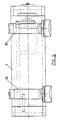
- the guide-bar 7 also has mounted between its ends a fixed bridge 10, Figs. 1, 4 and 5. As observed in Fig. 1, the system formed by the guide-bar 7 and the bridge 10 is mounted with the possibility of free turning between the laterals of the frame or chassis 1 of the machine, by means of bearings 11.
- the bridge 10 has fastened on the outside two end supports 12 and 13, which are carriers of pulleys 14 between which a belt 15 runs.
- a pulley 16 of greater diameter is mounted which is related by means of a transmission belt to the pulley 17 of smaller diameter which is solidary with the axis 18 of an activating motor 19.
- the support 5 of the engraving device 3 has an arm 20, Figs. 4 and 5, which overhangs in the direction opposite to that occupied by the striking point 4, Fig. 1, behind the bridge 10 and comes to cross perpendicularly the stretch of the belt 15 nearest to the guide-bar 7.
- This arm has, coming from its front surface, a transverse slot 21, Fig. 4, in which this lower section of the belt is introduced as adjusted, without possibility of their slipping from each other.
- the belt 15 will have an internal surface transversely ribbed and the slot 21 will be limited, at least on one of its surfaces, by a gearing 22 capable of being coupled between the ribbing of the belt 15, in order to assure mutual anchorage.
- the displacement of the belt 15 is caused by means of the motor 19, which will drag the arm 10 along the guide-bar 7, varying the direction of turn of the motor the change of direction of displacement of the support 5 is achieved and, thereby, the direction of displacement of the engraving device 3.
- the motor 19 utilized for causing the displacement of the slide 7 and thereby the engraving device 3, is mounted on the bridge 10 set at the ends of the guide-bar 7.
- the system formed by the guide-bar 7 and the bridge 10 is related to the tipping mechanism which is comprised of an arm 23 which is fastened perpendicularly at one of its ends to the said system, as a continuation of the bridge 10.
- the opposite end this arm 23 is capped in a toothed sector 24, Fig. 7, on an axis coinciding with the axis of turn 6 of the guide-bar 7.
- the toothed sector 24 engages with a pinion 25 with which a pulley 26 of greater diameter is solidary, which is related to a smaller pulley 27, solidary with the axis of an activating motor 28 which is mounted on the chassis 1 of the machine.
- the linear displacement of the support 5 and therefore of the engraving device 3 is achieved by means of a transmission mechanism 15 and an activating motor 19 which are mounted on the bridge 10 solidary with the guide-bar 7, while the motor 28 and transmission mechanism which causes the tipping of the engraving device 3 is mounted on the chassis 1 of the machine.
- a transmission mechanism 15 and an activating motor 19 which are mounted on the bridge 10 solidary with the guide-bar 7, while the motor 28 and transmission mechanism which causes the tipping of the engraving device 3 is mounted on the chassis 1 of the machine.
- the system of fastening of the support 5 to the transmission belt 15 is simple and of great safety.
- the motor 28, in turn, which will produce the tipping of the engraving device 3 is mounted on the structure of the machine and the transmission mechanism between said motor and the guide-bar 7 is comprised of a system of gears which makes it possible to achieve the maximum precision in the angle of tipping of the striking point 4.
- the machine can be equipped with upper handles 30 which facilitate its manipulation in the portable version.
- the system permits marking on two planes located up to 90° apart, only by increasing the arc of turn by means of the parts 24, Fig. 7.
Landscapes
- Manufacture Or Reproduction Of Printing Formes (AREA)
- Road Signs Or Road Markings (AREA)
- Processing And Handling Of Plastics And Other Materials For Molding In General (AREA)
- Developing Agents For Electrophotography (AREA)
- Graft Or Block Polymers (AREA)
- Ink Jet (AREA)
- Confectionery (AREA)
- Casting Devices For Molds (AREA)
- Recording Measured Values (AREA)
Priority Applications (1)
| Application Number | Priority Date | Filing Date | Title |
|---|---|---|---|
| SI9430171T SI0687577T1 (en) | 1994-06-16 | 1994-11-21 | Impact engraving machine |
Applications Claiming Priority (2)
| Application Number | Priority Date | Filing Date | Title |
|---|---|---|---|
| ES9401318 | 1994-06-16 | ||
| ES09401318A ES2110882B1 (es) | 1994-06-16 | 1994-06-16 | Maquina grabadora por impacto. |
Publications (2)
| Publication Number | Publication Date |
|---|---|
| EP0687577A1 EP0687577A1 (en) | 1995-12-20 |
| EP0687577B1 true EP0687577B1 (en) | 1998-07-01 |
Family
ID=8286615
Family Applications (1)
| Application Number | Title | Priority Date | Filing Date |
|---|---|---|---|
| EP94500189A Expired - Lifetime EP0687577B1 (en) | 1994-06-16 | 1994-11-21 | Impact engraving machine |
Country Status (8)
| Country | Link |
|---|---|
| EP (1) | EP0687577B1 (da) |
| AT (1) | ATE167833T1 (da) |
| BR (1) | BR9404108A (da) |
| CA (1) | CA2136393A1 (da) |
| DE (1) | DE69411370T2 (da) |
| DK (1) | DK0687577T3 (da) |
| ES (1) | ES2110882B1 (da) |
| SI (1) | SI0687577T1 (da) |
Families Citing this family (7)
| Publication number | Priority date | Publication date | Assignee | Title |
|---|---|---|---|---|
| ES2125137B1 (es) * | 1995-06-19 | 1999-12-01 | Tuceca S L | Maquina grabadora-expendedora de medallas con motivos alegoricos acuñados. |
| ES2133227B1 (es) * | 1996-11-07 | 2000-04-01 | Echevarria Lizarazu Pio | Maquina grabadora por impacto o rayado. |
| FR2792876B1 (fr) * | 1999-04-30 | 2001-06-08 | Technifor | Machine de marquage |
| FR2801238B1 (fr) * | 1999-11-24 | 2002-02-15 | Technomark | Machine de marquage modulable de pieces |
| GB2370812A (en) | 2001-01-09 | 2002-07-10 | Edward Pryor And Son Ltd | Handheld marking device including a marking stylus head horizontally and vertically movable about a frame to a required location by two stepper motors |
| IT1394745B1 (it) * | 2009-07-14 | 2012-07-13 | Ficep Spa | Dispositivo per la marcatura di superfici |
| ES2409067B1 (es) * | 2013-05-28 | 2014-04-22 | Pío ECHEVERRIA LIZARAZU | Máquina grabadora |
Family Cites Families (8)
| Publication number | Priority date | Publication date | Assignee | Title |
|---|---|---|---|---|
| US2262180A (en) * | 1940-02-17 | 1941-11-11 | Cunningham Co M E | Die holder |
| US3339279A (en) * | 1964-07-17 | 1967-09-05 | Robert H Sovar | Hollow engraving point and holder for engraving coated transparent sheets |
| CH573315A5 (da) * | 1974-01-08 | 1976-03-15 | Tesalon Anstalt | |
| US4089262A (en) * | 1974-05-14 | 1978-05-16 | Joachim Sopora | Apparatus for printing data on structural components |
| FR2459086A1 (fr) * | 1979-06-18 | 1981-01-09 | Clesid Sa | Procede et dispositif de marquage de produits siderurgiques |
| US4591279A (en) * | 1984-08-17 | 1986-05-27 | M. E. Cunningham Company | Marking machine for forming variable sized characters |
| FR2639860B1 (fr) * | 1988-12-01 | 1991-01-25 | Technifor Sarl | Dispositif de marquage par micro-percussion |
| FR2677911A1 (fr) * | 1991-06-21 | 1992-12-24 | Therond Marcel | Dispositif de marquage par micro-percussion permettant le trace de signes d'identification sur des objets en atmosphere polluee et procede mettant en óoeuvre ce dispositif. |
-
1994
- 1994-06-16 ES ES09401318A patent/ES2110882B1/es not_active Expired - Fee Related
- 1994-10-14 BR BR9404108A patent/BR9404108A/pt not_active IP Right Cessation
- 1994-11-21 AT AT94500189T patent/ATE167833T1/de active
- 1994-11-21 SI SI9430171T patent/SI0687577T1/xx unknown
- 1994-11-21 DK DK94500189T patent/DK0687577T3/da active
- 1994-11-21 EP EP94500189A patent/EP0687577B1/en not_active Expired - Lifetime
- 1994-11-21 DE DE69411370T patent/DE69411370T2/de not_active Expired - Lifetime
- 1994-11-22 CA CA002136393A patent/CA2136393A1/en not_active Abandoned
Also Published As
| Publication number | Publication date |
|---|---|
| DE69411370T2 (de) | 1999-03-11 |
| SI0687577T1 (en) | 1998-10-31 |
| EP0687577A1 (en) | 1995-12-20 |
| ES2110882A1 (es) | 1998-02-16 |
| BR9404108A (pt) | 1996-01-30 |
| CA2136393A1 (en) | 1995-12-17 |
| DK0687577T3 (da) | 1999-04-12 |
| DE69411370D1 (de) | 1998-08-06 |
| ES2110882B1 (es) | 1998-08-01 |
| ATE167833T1 (de) | 1998-07-15 |
Similar Documents
| Publication | Publication Date | Title |
|---|---|---|
| EP0687577B1 (en) | Impact engraving machine | |
| US3750792A (en) | Automatic media thickness compensator for a printer | |
| EP0418088B1 (en) | Plate adjusting mechanism for leaf-type printing machine | |
| JPS61233579A (ja) | プログラム可能なマ−ク付与機械 | |
| DE102009041527A1 (de) | Anlage zum Bedrucken von Behältern | |
| JPH0323135A (ja) | 帯状、板状又は線状材料を輸送する装置 | |
| DE2731849C3 (de) | Vorrichtung zum Prägestempeln von Walzgut | |
| GB2245850A (en) | Automatic spring-making machine | |
| US5493965A (en) | Impact engraving machine | |
| DE3234593C2 (de) | Antriebsmechanismus in einem automatischen Analysengerät | |
| US5353654A (en) | Testing facility for wrenches | |
| EP1170141A2 (de) | Vorrichtung zum Bedrucken eines Druckträgers | |
| US4431321A (en) | Computer controlled marking apparatus | |
| DE2742103A1 (de) | Zufuehreinrichtung, insbesondere zum bestuecken, entladen und transportieren von werkstuecken | |
| DE2850127C2 (de) | Vorrichtung zum Aufspielen eines Schneidprogramms für eine numerisch gesteuerte Modellschneidemaschine mit X- Y- Bahnsteuerung für Glasscheiben auf einen Impulsspeicher | |
| DE68925712T2 (de) | Anordnung für den Transport von Objekten | |
| EP0841195B1 (en) | Machine for engraving by impact or scratching | |
| DE69601511D1 (de) | Vorrichtung zum Zuführen einer kontinuierlich ankommenden Bahn in einer Station, die sie in angehaltenem Zustand bearbeitet | |
| US4401025A (en) | Device for pivoting a printing unit | |
| DE3215700A1 (de) | Handhabungseinrichtung, insbesondere zum bestuecken, entladen und transportieren von werkstuecken | |
| US4848942A (en) | Method and apparatus for marking on an arcuate surface | |
| DE3644391A1 (de) | Beschriftungsvorrichtung | |
| JP3267718B2 (ja) | プレスブレーキ | |
| KR910005896Y1 (ko) | 카드의 엠보스 인자장치 | |
| MXPA97008598A (en) | Impact or ray recording machine |
Legal Events
| Date | Code | Title | Description |
|---|---|---|---|
| PUAI | Public reference made under article 153(3) epc to a published international application that has entered the european phase |
Free format text: ORIGINAL CODE: 0009012 |
|
| AK | Designated contracting states |
Kind code of ref document: A1 Designated state(s): AT BE CH DE DK FR GB GR IE IT LI LU MC NL PT SE |
|
| RAX | Requested extension states of the european patent have changed |
Free format text: SI PAYMENT 941208 |
|
| 17P | Request for examination filed |
Effective date: 19951205 |
|
| 17Q | First examination report despatched |
Effective date: 19961016 |
|
| GRAG | Despatch of communication of intention to grant |
Free format text: ORIGINAL CODE: EPIDOS AGRA |
|
| GRAG | Despatch of communication of intention to grant |
Free format text: ORIGINAL CODE: EPIDOS AGRA |
|
| GRAH | Despatch of communication of intention to grant a patent |
Free format text: ORIGINAL CODE: EPIDOS IGRA |
|
| GRAH | Despatch of communication of intention to grant a patent |
Free format text: ORIGINAL CODE: EPIDOS IGRA |
|
| GRAA | (expected) grant |
Free format text: ORIGINAL CODE: 0009210 |
|
| AK | Designated contracting states |
Kind code of ref document: B1 Designated state(s): AT BE CH DE DK FR GB GR IE IT LI LU MC NL PT SE |
|
| AX | Request for extension of the european patent |
Free format text: SI PAYMENT 941208 |
|
| REF | Corresponds to: |
Ref document number: 167833 Country of ref document: AT Date of ref document: 19980715 Kind code of ref document: T |
|
| REG | Reference to a national code |
Ref country code: CH Ref legal event code: EP |
|
| REF | Corresponds to: |
Ref document number: 69411370 Country of ref document: DE Date of ref document: 19980806 |
|
| REG | Reference to a national code |
Ref country code: IE Ref legal event code: FG4D |
|
| PGFP | Annual fee paid to national office [announced via postgrant information from national office to epo] |
Ref country code: PT Payment date: 19981014 Year of fee payment: 5 |
|
| REG | Reference to a national code |
Ref country code: CH Ref legal event code: NV Representative=s name: BUGNION S.A. |
|
| PGFP | Annual fee paid to national office [announced via postgrant information from national office to epo] |
Ref country code: MC Payment date: 19981016 Year of fee payment: 5 |
|
| PGFP | Annual fee paid to national office [announced via postgrant information from national office to epo] |
Ref country code: GR Payment date: 19981102 Year of fee payment: 5 |
|
| ET | Fr: translation filed | ||
| PGFP | Annual fee paid to national office [announced via postgrant information from national office to epo] |
Ref country code: DK Payment date: 19981123 Year of fee payment: 5 |
|
| PGFP | Annual fee paid to national office [announced via postgrant information from national office to epo] |
Ref country code: CH Payment date: 19981204 Year of fee payment: 5 |
|
| REG | Reference to a national code |
Ref country code: PT Ref legal event code: SC4A Free format text: AVAILABILITY OF NATIONAL TRANSLATION Effective date: 19980915 |
|
| PGFP | Annual fee paid to national office [announced via postgrant information from national office to epo] |
Ref country code: LU Payment date: 19990301 Year of fee payment: 5 |
|
| PLBQ | Unpublished change to opponent data |
Free format text: ORIGINAL CODE: EPIDOS OPPO |
|
| PLBI | Opposition filed |
Free format text: ORIGINAL CODE: 0009260 |
|
| REG | Reference to a national code |
Ref country code: DK Ref legal event code: T3 |
|
| PLBF | Reply of patent proprietor to notice(s) of opposition |
Free format text: ORIGINAL CODE: EPIDOS OBSO |
|
| 26 | Opposition filed |
Opponent name: SIC MARQUAGE INDUSTRIEL ZAC DE LA BRAILLE Effective date: 19990401 |
|
| NLR1 | Nl: opposition has been filed with the epo |
Opponent name: SIC MARQUAGE INDUSTRIEL ZAC DE LA BRAILLE |
|
| PLBF | Reply of patent proprietor to notice(s) of opposition |
Free format text: ORIGINAL CODE: EPIDOS OBSO |
|
| PGFP | Annual fee paid to national office [announced via postgrant information from national office to epo] |
Ref country code: IE Payment date: 19991105 Year of fee payment: 6 |
|
| PGFP | Annual fee paid to national office [announced via postgrant information from national office to epo] |
Ref country code: SE Payment date: 19991116 Year of fee payment: 6 |
|
| PG25 | Lapsed in a contracting state [announced via postgrant information from national office to epo] |
Ref country code: LU Free format text: LAPSE BECAUSE OF NON-PAYMENT OF DUE FEES Effective date: 19991121 Ref country code: DK Free format text: LAPSE BECAUSE OF NON-PAYMENT OF DUE FEES Effective date: 19991121 |
|
| PG25 | Lapsed in a contracting state [announced via postgrant information from national office to epo] |
Ref country code: LI Free format text: LAPSE BECAUSE OF NON-PAYMENT OF DUE FEES Effective date: 19991130 Ref country code: GR Free format text: LAPSE BECAUSE OF NON-PAYMENT OF DUE FEES Effective date: 19991130 Ref country code: CH Free format text: LAPSE BECAUSE OF NON-PAYMENT OF DUE FEES Effective date: 19991130 |
|
| PG25 | Lapsed in a contracting state [announced via postgrant information from national office to epo] |
Ref country code: PT Free format text: LAPSE BECAUSE OF NON-PAYMENT OF DUE FEES Effective date: 20000531 Ref country code: MC Free format text: LAPSE BECAUSE OF NON-PAYMENT OF DUE FEES Effective date: 20000531 |
|
| REG | Reference to a national code |
Ref country code: CH Ref legal event code: PL |
|
| REG | Reference to a national code |
Ref country code: DK Ref legal event code: EBP |
|
| REG | Reference to a national code |
Ref country code: PT Ref legal event code: MM4A Free format text: LAPSE DUE TO NON-PAYMENT OF FEES Effective date: 20000531 |
|
| PG25 | Lapsed in a contracting state [announced via postgrant information from national office to epo] |
Ref country code: IE Free format text: LAPSE BECAUSE OF NON-PAYMENT OF DUE FEES Effective date: 20001121 |
|
| PG25 | Lapsed in a contracting state [announced via postgrant information from national office to epo] |
Ref country code: SE Free format text: THE PATENT HAS BEEN ANNULLED BY A DECISION OF A NATIONAL AUTHORITY Effective date: 20001129 |
|
| EUG | Se: european patent has lapsed |
Ref document number: 94500189.9 |
|
| PLBO | Opposition rejected |
Free format text: ORIGINAL CODE: EPIDOS REJO |
|
| REG | Reference to a national code |
Ref country code: IE Ref legal event code: MM4A |
|
| PLBN | Opposition rejected |
Free format text: ORIGINAL CODE: 0009273 |
|
| STAA | Information on the status of an ep patent application or granted ep patent |
Free format text: STATUS: OPPOSITION REJECTED |
|
| REG | Reference to a national code |
Ref country code: GB Ref legal event code: IF02 |
|
| 27O | Opposition rejected |
Effective date: 20010816 |
|
| NLR2 | Nl: decision of opposition | ||
| REG | Reference to a national code |
Ref country code: FR Ref legal event code: JE |
|
| PGFP | Annual fee paid to national office [announced via postgrant information from national office to epo] |
Ref country code: AT Payment date: 20131101 Year of fee payment: 20 Ref country code: GB Payment date: 20131127 Year of fee payment: 20 Ref country code: FR Payment date: 20131118 Year of fee payment: 20 Ref country code: DE Payment date: 20131127 Year of fee payment: 20 |
|
| PGFP | Annual fee paid to national office [announced via postgrant information from national office to epo] |
Ref country code: NL Payment date: 20131126 Year of fee payment: 20 Ref country code: IT Payment date: 20131126 Year of fee payment: 20 Ref country code: BE Payment date: 20131128 Year of fee payment: 20 |
|
| REG | Reference to a national code |
Ref country code: DE Ref legal event code: R071 Ref document number: 69411370 Country of ref document: DE |
|
| REG | Reference to a national code |
Ref country code: NL Ref legal event code: V4 Effective date: 20141121 |
|
| REG | Reference to a national code |
Ref country code: GB Ref legal event code: PE20 Expiry date: 20141120 |
|
| REG | Reference to a national code |
Ref country code: AT Ref legal event code: MK07 Ref document number: 167833 Country of ref document: AT Kind code of ref document: T Effective date: 20141121 |
|
| PG25 | Lapsed in a contracting state [announced via postgrant information from national office to epo] |
Ref country code: GB Free format text: LAPSE BECAUSE OF EXPIRATION OF PROTECTION Effective date: 20141120 |