EP0687611A1 - Méthode pour la fabrication des structures des véhicules - Google Patents
Méthode pour la fabrication des structures des véhicules Download PDFInfo
- Publication number
- EP0687611A1 EP0687611A1 EP95107900A EP95107900A EP0687611A1 EP 0687611 A1 EP0687611 A1 EP 0687611A1 EP 95107900 A EP95107900 A EP 95107900A EP 95107900 A EP95107900 A EP 95107900A EP 0687611 A1 EP0687611 A1 EP 0687611A1
- Authority
- EP
- European Patent Office
- Prior art keywords
- frame
- vehicle structure
- winding
- windows
- produced
- Prior art date
- Legal status (The legal status is an assumption and is not a legal conclusion. Google has not performed a legal analysis and makes no representation as to the accuracy of the status listed.)
- Granted
Links
- 238000000034 method Methods 0.000 title claims abstract description 32
- 238000004519 manufacturing process Methods 0.000 title claims abstract description 11
- 238000004804 winding Methods 0.000 claims abstract description 44
- 238000009413 insulation Methods 0.000 claims abstract description 22
- 230000002787 reinforcement Effects 0.000 claims abstract description 15
- 238000005516 engineering process Methods 0.000 claims abstract description 10
- 239000000463 material Substances 0.000 claims abstract description 9
- 239000003351 stiffener Substances 0.000 claims abstract description 9
- 230000003014 reinforcing effect Effects 0.000 claims abstract description 7
- 239000000853 adhesive Substances 0.000 claims description 5
- 230000001070 adhesive effect Effects 0.000 claims description 5
- 238000009434 installation Methods 0.000 claims description 4
- 238000009423 ventilation Methods 0.000 claims description 4
- 229920002430 Fibre-reinforced plastic Polymers 0.000 claims description 3
- 239000011151 fibre-reinforced plastic Substances 0.000 claims description 3
- 230000000284 resting effect Effects 0.000 claims 1
- 230000001681 protective effect Effects 0.000 abstract description 4
- 239000011162 core material Substances 0.000 description 5
- 239000002184 metal Substances 0.000 description 2
- 239000004033 plastic Substances 0.000 description 2
- 229920003023 plastic Polymers 0.000 description 2
- 229920000049 Carbon (fiber) Polymers 0.000 description 1
- 239000004917 carbon fiber Substances 0.000 description 1
- 230000001427 coherent effect Effects 0.000 description 1
- 238000005260 corrosion Methods 0.000 description 1
- 230000007797 corrosion Effects 0.000 description 1
- 238000010616 electrical installation Methods 0.000 description 1
- 239000004744 fabric Substances 0.000 description 1
- 239000006260 foam Substances 0.000 description 1
- 239000003365 glass fiber Substances 0.000 description 1
- 238000010438 heat treatment Methods 0.000 description 1
- VNWKTOKETHGBQD-UHFFFAOYSA-N methane Chemical compound C VNWKTOKETHGBQD-UHFFFAOYSA-N 0.000 description 1
- 239000011347 resin Substances 0.000 description 1
- 229920005989 resin Polymers 0.000 description 1
Images


Classifications
-
- B—PERFORMING OPERATIONS; TRANSPORTING
- B62—LAND VEHICLES FOR TRAVELLING OTHERWISE THAN ON RAILS
- B62D—MOTOR VEHICLES; TRAILERS
- B62D29/00—Superstructures, understructures, or sub-units thereof, characterised by the material thereof
- B62D29/04—Superstructures, understructures, or sub-units thereof, characterised by the material thereof predominantly of synthetic material
-
- B—PERFORMING OPERATIONS; TRANSPORTING
- B29—WORKING OF PLASTICS; WORKING OF SUBSTANCES IN A PLASTIC STATE IN GENERAL
- B29C—SHAPING OR JOINING OF PLASTICS; SHAPING OF MATERIAL IN A PLASTIC STATE, NOT OTHERWISE PROVIDED FOR; AFTER-TREATMENT OF THE SHAPED PRODUCTS, e.g. REPAIRING
- B29C53/00—Shaping by bending, folding, twisting, straightening or flattening; Apparatus therefor
- B29C53/56—Winding and joining, e.g. winding spirally
- B29C53/58—Winding and joining, e.g. winding spirally helically
- B29C53/583—Winding and joining, e.g. winding spirally helically for making tubular articles with particular features
-
- B—PERFORMING OPERATIONS; TRANSPORTING
- B61—RAILWAYS
- B61D—BODY DETAILS OR KINDS OF RAILWAY VEHICLES
- B61D17/00—Construction details of vehicle bodies
- B61D17/005—Construction details of vehicle bodies with bodies characterised by use of plastics materials
Definitions
- the present invention relates to a method for producing vehicle structures, preferably car bodies for rail vehicles, with a self-supporting lightweight structure made of fiber-reinforced plastics, the cylindrical longitudinal part of a car body being produced together with reinforcing elements, installation and ventilation ducts in continuously successive process steps by means of winding technology.
- a car body manufactured in the winding process which has an inner winding layer with partially molded, projecting and all-round stiffening ribs, a wrapped stiffening rib made of metal and between the inner and outer winding layer recesses for receiving ventilation, heating, electrical installations, Has lighting and sanitation.
- the simple sandwich structure consisting of an inner winding layer, intermediate insulation and an outer winding layer forms the self-supporting structure of the car body.
- European patent application 0 554 539 describes a similar method for producing a car body using winding technology.
- special longitudinal profiles arranged at the corners are wrapped, and appropriate blind covers are used for later window and door openings.
- This also self-supporting lightweight structure has a thin, first, inner insulation layer, and a second, outer insulation layer, which has the thickness of the reinforcement profiles.
- the insulation layers have partial thermal bridges as a result of the wrapped metallic reinforcement parts.
- the pairing also harbors fundamentally different materials, the risks of winding layer detachment and corrosion as a result of the occurring dillation forces with temperature fluctuations.
- a reinforcement frame to be manufactured separately means a conceptual foreign body that disrupts or makes it impossible for the manufacturing process to run continuously.
- the present invention is based on the object of using a method and using corresponding materials which eliminate these risks and which enable a more economical production of a body structure.
- the advantages of the invention essentially consist in the fact that the structure of the self-supporting structure consists of similar materials, that the effort for the window assembly is reduced and that the thermal insulation is improved.
- the strength of the vehicle structure can be adapted to the respective requirements through the process steps and the choice of material and that the structural strength can be influenced even further by external and internal means.
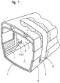
- FIG. 1 a vehicle structure 1 produced using winding technology is shown in cross-section and with a partially cut-open structure.
- the inner surface of the vehicle structure 1 is formed by an inner winding layer 5.
- An inner insulation layer 6 is applied over the inner winding layer 5, in which 6.1 cable channels 6.2 are inserted in recessed grooves.
- a device connection 16 is shown lying in a side wall above a cable duct 6.2.
- the inner insulation layer 6 is followed by a middle winding layer 7, on the top of which ceiling ducts 2 are placed in the form of a one-piece plastic profile in the roof area.
- the carriage windows 3 are located in the side walls in the subsequent outer insulation layer 8. Between the windows 3, an outer frame web 12 of a wrapped ring frame is visible.
- An outer winding layer 13 forms the outer skin of the vehicle structure 1.
- the section through the winding structure in FIG. 2 is shown in the window area of the vehicle structure 1. Partly Details already shown and named in FIG. 1 are enlarged and clearly shown here. Furthermore, the proportions of the individual layers are closer to reality.
- the structure begins on the inside with the first, the inner winding layer 5, which can have a thickness of, for example, two to five mm.
- Their structure preferably consists of resin-impregnated glass fiber layers in the form of rovings and fleeces.
- the inner insulation layer 6 placed and glued on this inner winding layer 5 is a few cm thick and can be made of a dimensionally stable, flexible and pressure-resistant foam plastic. In this inner insulation layer 6, the grooves 6.1 are cut out, cut out or milled out and then fitted with cable channels 6.2.
- Some cables 6.3 are inserted in the cable duct 6.2 shown.
- the cable channels 6.2 are preferably open in the direction of the inner winding layer and closed in the direction of the middle winding layer 7 lying thereon.
- the height of the cable ducts 6.2 corresponds to the thickness of the inner insulation layer 6 in order to obtain a flat contact surface for the middle winding layer 7.
- a first sandwich structure of the vehicle structure 1 is completed with this middle winding layer 7.
- prefabricated windows 3 are placed on the middle winding layer 7 and fixed in their final position.
- the windows 3 consist of an outer frame 3.1, an inner frame 3.3 connected with an adhesive joint 3.2 and a double glazing 3.4 used in the inner frame 3.3.
- the outer surfaces and the inner surfaces of the windows 3 are each covered with an easily removable protective film 4
- the area in the vertical alignment above and below the windows 3, as shown in FIG. 3, is filled all around the vehicle structure 1 with an outer insulation layer 8 of the same thickness as the outer window frames 3.1.
- a round frame 17 reinforcing the structure is wrapped with the next process steps.
- an inner frame web 9 is wound into the channel base in the form of a multi-layer winding.
- a frame core 11 is then inserted in the middle of the inner frame web 9, the width of which is, for example, approximately half the channel width, and which consists of a dimensionally stable, light core material.
- the height of the frame core 11 is a few mm less than the thickness of the window 3.
- Frame flanges 10 are wrapped in the side channels thus created up to the same height of the frame core 11.
- the outer frame web 12 is wound onto the insulation layer 11 and the two lateral frame flanges 10.
- the annular frame 17 forms a rectangular profile which reinforces the structure and has a stiffening core of great strength. With the appropriate choice of material, a strength comparable to that of a round metal frame is achieved.
- carbon fiber fabrics impregnated with special resin are processed as high-strength materials.
- the wrapped annular frame 17 forms with the outer insulation layer 8 and the outside of the window 3 a uniform flat surface as the basis for an outer winding layer 13 that closes the structure.
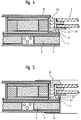
- FIG. 4 shows how the windows 3 covered by the outer winding layer 13 after the winding operations have been completed are exposed by cutting out this outer winding layer 13.
- the protective film 4 has been removed and a final joint 3.5 has been introduced, the outside of the structure is largely finished.
- the structural layers 5, 6 and 7 must be cut to match the contours of the windows 3, flush or flush with the inside edge of the outer frame 3.1, except for the surface of the inner frame 3.3. to expose the inside of the window 3, on which the protective film 4 is then also removed.
- an angle frame 14 covering the inner winding layer 5 is also used which covers a few cm.
- a reinforcing frame 15 is used as an additional element in this illustration on the outside of the structure near the window 3. With this reinforcement frame 15, increased requirements regarding strength and finish of the outer skin of a vehicle are met.
- FIG. 6 shows the perspective exterior view of the vehicle structure 1 in an intermediate stage essential for the method according to the invention.
- the first sandwich structure consisting of inner winding layer 5, inner insulation layer 6 and middle winding layer 7 is present here.
- the prepared molded part with the ceiling channels 2 is placed on the top and the windows 3 are attached in their final position on the sides.
- longitudinal stiffeners 18 are attached laterally at the level of the buffer level. These longitudinal stiffeners 18 provide the compressive strength required for a rail vehicle parallel to the longitudinal direction of the vehicle.
- the longitudinal stiffeners 18 are of the same type as the ring frames 17 and therefore also have the same mechanical strength. They are essentially designed as wound rectangular hollow profiles or pultrusion profiles with a foamed cavity, each have the length of a window 3 and are supported on the end faces of the ring ribs 17.
- longitudinal stiffeners 18 are also used in further locations between the ring frames 17 in the longitudinal direction, for example in the bottom and Ceiling area and on the corner parts of the vehicle structure 1.
- This vehicle structure 1 with the coherent reinforcement structure produced during the winding process, consisting of ring frames 17 and longitudinal reinforcements 18, the windows 3 used with the reinforcement frames 14, the ceiling channels 2, the three winding layers 5, 7, 13 and the two insulation layers 6 and 8 have a very high rigidity and strength with high quality of heat and sound insulation.
- FIG. 7 the spaces between the windows 3 and the longitudinal stiffeners 18 are filled with the outer insulation layer 8 and two of the three provided ring frames 17 are wrapped.
- the still empty, recessed channel for the third ring frame 17 is visible in the front.
- Ring frames 17 are used in a vehicle structure 1 for a car body not only between the windows 3, but also where structural reinforcement is sensible and necessary, for example in the case of door jambs as a supporting element for the door mechanism and as edge reinforcement at the car ends for the attachment of front parts and driver's cabins.
- the result of the method according to the invention is a double sandwich structure with an inner insulation layer 6 receiving cable channels 6.2, which is closed with an inner and middle winding layer 5 and 7 and an outer one, the stiffeners described in the form of the ring ribs 17 and longitudinal stiffeners 18 and the windows 3 and ceiling channels 2 receiving the outer insulation layer, which is finally covered with an outer winding layer 13.
- the cable channels 6.2 can be drilled at designated locations and device connections 16 can be made, such as for lighting and audio connections or for feeding private devices such as Razors, PC's, dictation machines, typewriters, etc. If necessary, the reinforcement frames 15 already described can be used on the outside of the windows.
- the inner frame part projecting into the adhesive joint 3.2 absorbs additional longitudinal forces in a force-locking connection with the ring ribs 17 and the outer visible part results in an aesthetically and mechanically satisfactory covering of the frame part of the window 3 and of the cutout in the outer winding layer 13.
Landscapes
- Engineering & Computer Science (AREA)
- Mechanical Engineering (AREA)
- Architecture (AREA)
- Structural Engineering (AREA)
- Chemical & Material Sciences (AREA)
- Combustion & Propulsion (AREA)
- Transportation (AREA)
- Body Structure For Vehicles (AREA)
- Recrystallisation Techniques (AREA)
- Holo Graphy (AREA)
- Vehicle Interior And Exterior Ornaments, Soundproofing, And Insulation (AREA)
- Laminated Bodies (AREA)
- Steroid Compounds (AREA)
- Transition And Organic Metals Composition Catalysts For Addition Polymerization (AREA)
- Bending Of Plates, Rods, And Pipes (AREA)
- Moulding By Coating Moulds (AREA)
- Seal Device For Vehicle (AREA)
- Glass Compositions (AREA)
Applications Claiming Priority (3)
| Application Number | Priority Date | Filing Date | Title |
|---|---|---|---|
| CH187194 | 1994-06-14 | ||
| CH187194 | 1994-06-14 | ||
| CH1871/94 | 1994-06-14 |
Publications (2)
| Publication Number | Publication Date |
|---|---|
| EP0687611A1 true EP0687611A1 (fr) | 1995-12-20 |
| EP0687611B1 EP0687611B1 (fr) | 2000-01-05 |
Family
ID=4220549
Family Applications (1)
| Application Number | Title | Priority Date | Filing Date |
|---|---|---|---|
| EP95107900A Expired - Lifetime EP0687611B1 (fr) | 1994-06-14 | 1995-05-24 | Méthode pour la fabrication des structures des véhicules |
Country Status (9)
| Country | Link |
|---|---|
| US (1) | US5669999A (fr) |
| EP (1) | EP0687611B1 (fr) |
| JP (1) | JPH07329778A (fr) |
| AT (1) | ATE188422T1 (fr) |
| AU (1) | AU685612B2 (fr) |
| CA (1) | CA2150893A1 (fr) |
| DE (1) | DE59507553D1 (fr) |
| FI (1) | FI952870A7 (fr) |
| NO (1) | NO305232B1 (fr) |
Cited By (5)
| Publication number | Priority date | Publication date | Assignee | Title |
|---|---|---|---|---|
| FR2753673A1 (fr) | 1996-09-25 | 1998-03-27 | Deutsche Waggonbau Ag | Structure en coque en matiere plastique armee de fibres pour vehicules ou conteneurs, en particulier pour caisses de vehicule ferroviaire |
| FR2760397A1 (fr) * | 1997-03-06 | 1998-09-11 | Jean Alphonse David | Ensemble structural en materiaux composites thermodurcissables composant un chaudron de voiture de transport et son procede de fabrication |
| EP0982212A1 (fr) | 1998-08-27 | 2000-03-01 | Inventio Ag | Dispositif pour l'introduction d'efforts dans un élément construit de fibres composites |
| WO2001085517A1 (fr) * | 2000-05-12 | 2001-11-15 | Constructions Industrielles De La Mediterranee (C.N.I.M.) | Procede d'elaboration d'une structure en materiau composite, notamment pour vehicules ferroviaires |
| DE10155820A1 (de) * | 2001-11-15 | 2003-06-05 | Bombardier Transp Gmbh | Wagenkasten für Fahrzeuge und Verfahren zu dessen Herstellung |
Families Citing this family (25)
| Publication number | Priority date | Publication date | Assignee | Title |
|---|---|---|---|---|
| US6092472A (en) * | 1996-07-19 | 2000-07-25 | Trn Business Trust | Composite box structure for a railway car |
| US6000342A (en) * | 1996-07-19 | 1999-12-14 | Trn Business Trust | Railway car underframe for an insulated composite boxcar |
| USH1872H (en) * | 1997-03-03 | 2000-10-03 | The United States Of America As Represented By The Secretary Of The Air Force | Modular fiber reinforced plastic enclosed bridge |
| NL1006199C1 (nl) * | 1997-03-14 | 1998-09-15 | Fokker Special Products | Voertuigconstructie. |
| DE19903281A1 (de) * | 1999-01-28 | 2000-08-03 | Abb Daimler Benz Transp | Schienenfahrzeug mit selbsttragendem Wagenkasten |
| US6976333B2 (en) * | 2001-01-11 | 2005-12-20 | Steven Sims | Recoil reducing accessories for firearms |
| US6712390B1 (en) | 2001-07-06 | 2004-03-30 | Joseph P. Spinelli | Vehicular impact resistant barrier system |
| US20050161975A1 (en) * | 2004-01-23 | 2005-07-28 | Nieminski Brant R. | Modular bus body assembly |
| JP2007518638A (ja) * | 2004-01-23 | 2007-07-12 | ファースト グリーン パーク プロプライエタリー リミテッド | パネル構造及びそれから製造される組立品 |
| US8444087B2 (en) * | 2005-04-28 | 2013-05-21 | The Boeing Company | Composite skin and stringer structure and method for forming the same |
| US7721495B2 (en) * | 2005-03-31 | 2010-05-25 | The Boeing Company | Composite structural members and methods for forming the same |
| US20060222837A1 (en) * | 2005-03-31 | 2006-10-05 | The Boeing Company | Multi-axial laminate composite structures and methods of forming the same |
| US7740932B2 (en) * | 2005-03-31 | 2010-06-22 | The Boeing Company | Hybrid fiberglass composite structures and methods of forming the same |
| US7467763B2 (en) * | 2005-06-03 | 2008-12-23 | Kismarton Max U | Composite landing gear apparatus and methods |
| US20060237588A1 (en) * | 2005-03-31 | 2006-10-26 | The Boeing Company | Composite structural member having an undulating web and method for forming the same |
| US7748119B2 (en) * | 2005-06-03 | 2010-07-06 | The Boeing Company | Method for manufacturing composite components |
| US20070052554A1 (en) * | 2005-08-24 | 2007-03-08 | The Boeing Company | Methods and systems for logistics health status display |
| US20070050104A1 (en) * | 2005-08-24 | 2007-03-01 | The Boeing Company | Methods and systems for logistics health status reasoner |
| DE102008027429B4 (de) * | 2008-06-09 | 2016-01-28 | Daimler Ag | Verfahren zur Herstellung einer Rohbaustruktur für einen Kraftwagen |
| CN103465919B (zh) * | 2009-03-30 | 2016-03-02 | 川崎重工业株式会社 | 铁道车辆结构体 |
| CN102066178B (zh) * | 2009-06-10 | 2016-01-13 | 川崎重工业株式会社 | 铁道车辆结构体的增强方法以及铁道车辆结构体 |
| US8215692B2 (en) * | 2009-07-21 | 2012-07-10 | Navistar Canada, Inc. | Adjustable length delivery vehicle |
| JP2012020592A (ja) * | 2010-07-12 | 2012-02-02 | Kawasaki Heavy Ind Ltd | 鉄道車両の構体構造 |
| RU2558400C2 (ru) * | 2010-09-20 | 2015-08-10 | Бомбардир Транспортацион Гмбх | Легкая композитная структура кабины рельсового транспортного средства |
| US9878773B2 (en) | 2012-12-03 | 2018-01-30 | The Boeing Company | Split resistant composite laminate |
Citations (3)
| Publication number | Priority date | Publication date | Assignee | Title |
|---|---|---|---|---|
| GB1490575A (en) | 1974-12-02 | 1977-11-02 | Pikaz Inzenyrsky Podnik | Body for a road or rail vehicle or for a container |
| EP0554539A1 (fr) | 1992-01-28 | 1993-08-11 | Inventio Ag | Procédé de fabrication de caisses monogues de véhicules |
| EP0582544A1 (fr) * | 1992-08-05 | 1994-02-09 | Alusuisse-Lonza Services Ag | Laisse de voitures ferroviaires |
Family Cites Families (3)
| Publication number | Priority date | Publication date | Assignee | Title |
|---|---|---|---|---|
| US4025675A (en) * | 1973-12-19 | 1977-05-24 | Messerschmitt-Bolkow-Blohm Gmbh | Reinforced laminates |
| ATE149913T1 (de) * | 1992-07-10 | 1997-03-15 | Inventio Ag | Verfahren zur integralen herstellung eines innenausbaus für wagenkasten |
| FR2700729B1 (fr) * | 1993-01-25 | 1995-03-31 | David Jean | Procédé de fabrication de caisson à parois multicellulaires en matériaux composites thermodurcissables réalisés par enroulement. |
-
1995
- 1995-05-24 DE DE59507553T patent/DE59507553D1/de not_active Expired - Fee Related
- 1995-05-24 EP EP95107900A patent/EP0687611B1/fr not_active Expired - Lifetime
- 1995-05-24 AT AT95107900T patent/ATE188422T1/de not_active IP Right Cessation
- 1995-06-02 CA CA002150893A patent/CA2150893A1/fr not_active Abandoned
- 1995-06-09 AU AU20591/95A patent/AU685612B2/en not_active Ceased
- 1995-06-12 US US08/489,500 patent/US5669999A/en not_active Expired - Fee Related
- 1995-06-12 FI FI952870A patent/FI952870A7/fi unknown
- 1995-06-13 NO NO952319A patent/NO305232B1/no not_active IP Right Cessation
- 1995-06-14 JP JP7147425A patent/JPH07329778A/ja active Pending
Patent Citations (3)
| Publication number | Priority date | Publication date | Assignee | Title |
|---|---|---|---|---|
| GB1490575A (en) | 1974-12-02 | 1977-11-02 | Pikaz Inzenyrsky Podnik | Body for a road or rail vehicle or for a container |
| EP0554539A1 (fr) | 1992-01-28 | 1993-08-11 | Inventio Ag | Procédé de fabrication de caisses monogues de véhicules |
| EP0582544A1 (fr) * | 1992-08-05 | 1994-02-09 | Alusuisse-Lonza Services Ag | Laisse de voitures ferroviaires |
Cited By (6)
| Publication number | Priority date | Publication date | Assignee | Title |
|---|---|---|---|---|
| FR2753673A1 (fr) | 1996-09-25 | 1998-03-27 | Deutsche Waggonbau Ag | Structure en coque en matiere plastique armee de fibres pour vehicules ou conteneurs, en particulier pour caisses de vehicule ferroviaire |
| FR2760397A1 (fr) * | 1997-03-06 | 1998-09-11 | Jean Alphonse David | Ensemble structural en materiaux composites thermodurcissables composant un chaudron de voiture de transport et son procede de fabrication |
| EP0982212A1 (fr) | 1998-08-27 | 2000-03-01 | Inventio Ag | Dispositif pour l'introduction d'efforts dans un élément construit de fibres composites |
| WO2001085517A1 (fr) * | 2000-05-12 | 2001-11-15 | Constructions Industrielles De La Mediterranee (C.N.I.M.) | Procede d'elaboration d'une structure en materiau composite, notamment pour vehicules ferroviaires |
| FR2808756A1 (fr) * | 2000-05-12 | 2001-11-16 | Mediterranee Const Ind | Procede d'elaboration d'une structure en materiau composite, notamment pour vehicules ferroviaires |
| DE10155820A1 (de) * | 2001-11-15 | 2003-06-05 | Bombardier Transp Gmbh | Wagenkasten für Fahrzeuge und Verfahren zu dessen Herstellung |
Also Published As
| Publication number | Publication date |
|---|---|
| EP0687611B1 (fr) | 2000-01-05 |
| FI952870A0 (fi) | 1995-06-12 |
| NO952319L (no) | 1995-12-15 |
| FI952870A7 (fi) | 1995-12-15 |
| JPH07329778A (ja) | 1995-12-19 |
| AU685612B2 (en) | 1998-01-22 |
| ATE188422T1 (de) | 2000-01-15 |
| AU2059195A (en) | 1995-12-21 |
| DE59507553D1 (de) | 2000-02-10 |
| NO952319D0 (no) | 1995-06-13 |
| NO305232B1 (no) | 1999-04-26 |
| CA2150893A1 (fr) | 1995-12-15 |
| US5669999A (en) | 1997-09-23 |
Similar Documents
| Publication | Publication Date | Title |
|---|---|---|
| EP0687611A1 (fr) | Méthode pour la fabrication des structures des véhicules | |
| DE69003682T2 (de) | Feuchtigkeitsundurchlässiges abstandhalterprofil für isolierglas. | |
| EP1288077B1 (fr) | Garniture de pavillon avec construction en sandwich et sa méthode de production | |
| EP0369134A1 (fr) | Cellule de véhicule | |
| DE3722490A1 (de) | Bodenplatte fuer ein kraftfahrzeug | |
| DE19751277C2 (de) | Fenster, Türe oder dergl. | |
| DE19649526C2 (de) | Fahrzeugkopf eines Eisenbahnfahrzeugs mit einer Führerkabine | |
| DE2841177A1 (de) | Personenfahrzeug mit eingeklebten fensterscheiben | |
| DE69929447T2 (de) | Ein strukturelles element das zumindest einen teil der hülle des wagenkastens eines schienenfahrzeuges bildet | |
| DE3101551C2 (de) | Türzarge | |
| AT523544B1 (de) | Kunststoff-Metall-Fenstersystem | |
| DE69021113T2 (de) | Eisenbahnpersonenwagenkasten und dessen Herstellungsverfahren. | |
| DE3608306A1 (de) | Dachausbildung von nutzfahrzeugen | |
| DE4007391C2 (de) | Befestigungsflansch für eine Abdeckleiste | |
| DE19739291C1 (de) | Verfahren zum Herstellen von Ausschnitten in Faserverbund-Sandwichstrukturen und dadurch hergestellter Ausschnitt | |
| WO2008092699A1 (fr) | Dispositif d'inspection, en particulier élément de recouvrement d'inspection | |
| DE10212452A1 (de) | Verfahren zur Herstellung eines wärmedämmenden Isolier- und Verbindungssteges und nach diesem Verfahren hergestellter Isolier- und Verbindungssteg | |
| DE8619573U1 (de) | Verstärkungsträger für Profilleisten | |
| DE3346818C2 (de) | Rollenbahn | |
| DE1580992A1 (de) | Verfahren zum Herstellen des Aufbaues eines Fahrzeuges,insbesondere des Aufbaues eines Eisenbahnwaggons fuer den Personenverkehr | |
| DE202007013805U1 (de) | Chassisteil für Wagenaufbauten | |
| DE2908346A1 (de) | Rahmen- und/oder strukturbauelement | |
| DE3520479C1 (de) | Kraftfahrzeugtür | |
| DE3408995C2 (de) | Eckverbindung für Profilteile | |
| DE8128016U1 (de) | "anschlagprofil aus elastischem material" |
Legal Events
| Date | Code | Title | Description |
|---|---|---|---|
| PUAI | Public reference made under article 153(3) epc to a published international application that has entered the european phase |
Free format text: ORIGINAL CODE: 0009012 |
|
| AK | Designated contracting states |
Kind code of ref document: A1 Designated state(s): AT BE CH DE DK ES FR GB IT LI PT SE |
|
| 17P | Request for examination filed |
Effective date: 19960517 |
|
| 17Q | First examination report despatched |
Effective date: 19970904 |
|
| GRAG | Despatch of communication of intention to grant |
Free format text: ORIGINAL CODE: EPIDOS AGRA |
|
| GRAG | Despatch of communication of intention to grant |
Free format text: ORIGINAL CODE: EPIDOS AGRA |
|
| GRAH | Despatch of communication of intention to grant a patent |
Free format text: ORIGINAL CODE: EPIDOS IGRA |
|
| GRAH | Despatch of communication of intention to grant a patent |
Free format text: ORIGINAL CODE: EPIDOS IGRA |
|
| GRAA | (expected) grant |
Free format text: ORIGINAL CODE: 0009210 |
|
| AK | Designated contracting states |
Kind code of ref document: B1 Designated state(s): AT BE CH DE DK ES FR GB IT LI PT SE |
|
| PG25 | Lapsed in a contracting state [announced via postgrant information from national office to epo] |
Ref country code: SE Free format text: THE PATENT HAS BEEN ANNULLED BY A DECISION OF A NATIONAL AUTHORITY Effective date: 20000105 Ref country code: IT Free format text: LAPSE BECAUSE OF FAILURE TO SUBMIT A TRANSLATION OF THE DESCRIPTION OR TO PAY THE FEE WITHIN THE PRE;WARNING: LAPSES OF ITALIAN PATENTS WITH EFFECTIVE DATE BEFORE 2007 MAY HAVE OCCURRED AT ANY TIME BEFORE 2007. THE CORRECT EFFECTIVE DATE MAY BE DIFFERENT FROM THE ONE RECORDED.SCRIBED TIME-LIMIT Effective date: 20000105 Ref country code: GB Free format text: LAPSE BECAUSE OF FAILURE TO SUBMIT A TRANSLATION OF THE DESCRIPTION OR TO PAY THE FEE WITHIN THE PRESCRIBED TIME-LIMIT Effective date: 20000105 Ref country code: FR Free format text: LAPSE BECAUSE OF FAILURE TO SUBMIT A TRANSLATION OF THE DESCRIPTION OR TO PAY THE FEE WITHIN THE PRESCRIBED TIME-LIMIT Effective date: 20000105 Ref country code: ES Free format text: THE PATENT HAS BEEN ANNULLED BY A DECISION OF A NATIONAL AUTHORITY Effective date: 20000105 |
|
| REF | Corresponds to: |
Ref document number: 188422 Country of ref document: AT Date of ref document: 20000115 Kind code of ref document: T |
|
| REG | Reference to a national code |
Ref country code: CH Ref legal event code: EP |
|
| REF | Corresponds to: |
Ref document number: 59507553 Country of ref document: DE Date of ref document: 20000210 |
|
| PG25 | Lapsed in a contracting state [announced via postgrant information from national office to epo] |
Ref country code: PT Free format text: LAPSE BECAUSE OF FAILURE TO SUBMIT A TRANSLATION OF THE DESCRIPTION OR TO PAY THE FEE WITHIN THE PRESCRIBED TIME-LIMIT Effective date: 20000405 Ref country code: DK Free format text: LAPSE BECAUSE OF FAILURE TO SUBMIT A TRANSLATION OF THE DESCRIPTION OR TO PAY THE FEE WITHIN THE PRESCRIBED TIME-LIMIT Effective date: 20000405 |
|
| PG25 | Lapsed in a contracting state [announced via postgrant information from national office to epo] |
Ref country code: AT Free format text: LAPSE BECAUSE OF NON-PAYMENT OF DUE FEES Effective date: 20000524 |
|
| PG25 | Lapsed in a contracting state [announced via postgrant information from national office to epo] |
Ref country code: BE Free format text: LAPSE BECAUSE OF NON-PAYMENT OF DUE FEES Effective date: 20000531 |
|
| EN | Fr: translation not filed | ||
| GBV | Gb: ep patent (uk) treated as always having been void in accordance with gb section 77(7)/1977 [no translation filed] |
Effective date: 20000105 |
|
| PLBE | No opposition filed within time limit |
Free format text: ORIGINAL CODE: 0009261 |
|
| STAA | Information on the status of an ep patent application or granted ep patent |
Free format text: STATUS: NO OPPOSITION FILED WITHIN TIME LIMIT |
|
| BERE | Be: lapsed |
Owner name: INVENTIO A.G. Effective date: 20000531 |
|
| 26N | No opposition filed | ||
| PGFP | Annual fee paid to national office [announced via postgrant information from national office to epo] |
Ref country code: DE Payment date: 20020511 Year of fee payment: 8 |
|
| PGFP | Annual fee paid to national office [announced via postgrant information from national office to epo] |
Ref country code: CH Payment date: 20020816 Year of fee payment: 8 |
|
| PG25 | Lapsed in a contracting state [announced via postgrant information from national office to epo] |
Ref country code: LI Free format text: LAPSE BECAUSE OF NON-PAYMENT OF DUE FEES Effective date: 20030531 Ref country code: CH Free format text: LAPSE BECAUSE OF NON-PAYMENT OF DUE FEES Effective date: 20030531 |
|
| PG25 | Lapsed in a contracting state [announced via postgrant information from national office to epo] |
Ref country code: DE Free format text: LAPSE BECAUSE OF NON-PAYMENT OF DUE FEES Effective date: 20031202 |
|
| REG | Reference to a national code |
Ref country code: CH Ref legal event code: PL |