EP0687616B1 - Servolenkung - Google Patents
Servolenkung Download PDFInfo
- Publication number
- EP0687616B1 EP0687616B1 EP95109120A EP95109120A EP0687616B1 EP 0687616 B1 EP0687616 B1 EP 0687616B1 EP 95109120 A EP95109120 A EP 95109120A EP 95109120 A EP95109120 A EP 95109120A EP 0687616 B1 EP0687616 B1 EP 0687616B1
- Authority
- EP
- European Patent Office
- Prior art keywords
- fluid
- power cylinder
- fluid chambers
- reservoir
- power
- Prior art date
- Legal status (The legal status is an assumption and is not a legal conclusion. Google has not performed a legal analysis and makes no representation as to the accuracy of the status listed.)
- Expired - Lifetime
Links
- 239000012530 fluid Substances 0.000 claims description 86
- 230000007935 neutral effect Effects 0.000 claims description 29
- 238000010586 diagram Methods 0.000 description 5
- 238000010276 construction Methods 0.000 description 2
- 230000003247 decreasing effect Effects 0.000 description 1
- 230000003111 delayed effect Effects 0.000 description 1
- 238000012986 modification Methods 0.000 description 1
- 230000004048 modification Effects 0.000 description 1
- 239000007787 solid Substances 0.000 description 1
Images



Classifications
-
- B—PERFORMING OPERATIONS; TRANSPORTING
- B62—LAND VEHICLES FOR TRAVELLING OTHERWISE THAN ON RAILS
- B62D—MOTOR VEHICLES; TRAILERS
- B62D5/00—Power-assisted or power-driven steering
- B62D5/06—Power-assisted or power-driven steering fluid, i.e. using a pressurised fluid for most or all the force required for steering a vehicle
- B62D5/08—Power-assisted or power-driven steering fluid, i.e. using a pressurised fluid for most or all the force required for steering a vehicle characterised by type of steering valve used
- B62D5/083—Rotary valves
-
- B—PERFORMING OPERATIONS; TRANSPORTING
- B62—LAND VEHICLES FOR TRAVELLING OTHERWISE THAN ON RAILS
- B62D—MOTOR VEHICLES; TRAILERS
- B62D6/00—Arrangements for automatically controlling steering depending on driving conditions sensed and responded to, e.g. control circuits
- B62D6/02—Arrangements for automatically controlling steering depending on driving conditions sensed and responded to, e.g. control circuits responsive only to vehicle speed
Definitions
- the present invention relates to a hydraulic power steering apparatus suitable for use in automobiles and the like.
- the control valve 5 is composed of a first control portion 6 having variable orifices 6A-6D of center-open type, and a second control portion 7 having variable orifices 7A and 7B of center-closed type communicating with the pump 1 and variable orifices 7C and 7D of center-open type communicating with the reservoir 2.
- the center-closed variable orifices 7A and 7B since the center-closed variable orifices 7A and 7B remains closed around the neutral position, the differential pressure between both fluid chambers 3A and 3B is maintained to be substantially zero.
- the center-closed variable orifice 7B communicating with the pump 1 begins to open, and the opening area of the variable orifice 7D communicating with the reservoir 2 is reduced, so that the differential pressure is generated between the both fluid chambers 3A and 3B to assist the steering operation.
- the differential pressure between the both fluid chambers 3A and 3B of the power cylinder 3 can be prevented from increasing around the neutral position, whereby the total rigidity of the steering wheel around the neutral position can be increased.
- power assistance at a low vehicle speed may be desirably more than that at a high speed and is required even around the neutral position of the steering wheel.
- the conventional control valve 5 has a fixed hydraulic characteristic. Namely, the differential pressure across the power cylinder 3 is changed in dependence upon the rotational angle of the steering wheel, and has no relation with the vehicle speed. As a result, the total rigidity of the steering wheel is maintained to be high around the neutral position and therefore, a suitable power assistance can not be obtained in accordance with the vehicle speed.
- an object of the present invention to provide an improved power steering apparatus capable of providing a driver with an improved steering feeling around the neutral position of a steering wheel.
- Another object of the present invention is to provide an improved power steering apparatus capable of obtaining a desired power assistance at any vehicle speed.
- a further object of the present invention is to provide an improved power steering apparatus capable of improving the return of a steering wheel.
- the present invention provides a power steering apparatus comprising a fluid source for supplying pressurized fluid, a power cylinder having a pair of fluid chambers and operable to generate assisting power, a control valve, and a drain control mechanism.
- the control valve is composed of first and second control portions.
- the first control portion has at least one path connecting the fluid source and the reservoir, and each of the paths is formed with a variable orifice of center-open type, to control the flow of pressurized fluid from the fluid source to the reservoir.
- the second control portion has two supply paths communicating the fluid source respectively with the pair of fluid chambers of the power cylinder, each of the supply paths being formed with a variable orifice of center-open type, and two drain paths communicating the fluid chambers of said power cylinder respectively with the reservoir, each of the drain paths being formed with a variable orifice of center-closed type.
- the drain control mechanism is responsive to differential pressure between the fluid chambers of the power cylinder to control the communication of one fluid chamber under high pressure with the reservoir, and responsive to a vehicle speed to control the communication of both fluid chambers with said reservoir.
- the differential pressure across the power cylinder is maintained to be substantially zero when the steering wheel is around the neutral position.
- the differential pressure across the power cylinder is generated in accordance with the relative rotational angle of the control valve even when the steering wheel is around the neutral position. Therefore, the total rigidity of the steering wheel around the neutral position can be changed in accordance with the vehicle speed, and a desired power assistance can be obtained at any vehicle speed.
- one of the fluid chambers of the power cylinder is in communication with the other thereof through the center-open variable orifices of the second control portion. This permits the fluid to flow between the fluid chambers, so that the returning of the steering wheel can be improved.
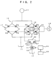
- a hydraulic power steering apparatus is mainly composed of a pump 10 by which pressurized fluid is discharged at constant flow rate, a reservoir 11, a power cylinder 12 for assisting the steering operation, a rotary control valve 14.
- the rotary control valve 14 is responsive to rotation of a steering wheel 13 so as to control the flow of the pressurized fluid from the pump 10 to the power cylinder 12.
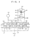
- the rotary control valve 14, shown as an enlarged development view in FIG. 3, is composed of a valve shaft 15 coupled to the steering wheel 13 for rotation therewith, a valve body 16 arranged to surround the valve shaft 15 in a coaxial relationship therewith, a torsion bar (not shown) connecting the valve shaft 15 with the valve body 16 in the manner that they are relatively rotatable, and a valve housing (not shown) receiving the above-mentioned components therein.
- the valve body 16 is mechanically connected to a steering linkage to which hydraulic force generated by the power cylinder 12 is applied.
- Each of the outer surface of the valve shaft 15 and the inner surface of the valve body 16 is provided with a plurality of axial slots, which are formed at predetermined intervals in the circumferential direction.
- two kinds of control portions i.e., a first control portion 17 and a second control portion 18 are formed between the valve shaft 15 and the valve body 16 alternatively at intervals of 90 degrees in the circumferential direction so as to control the flow of pressurized fluid.
- the first control portion 17 has four fluid paths which are connected to the pump 10 and the reservoir 11, and four variable orifices V1, V2, V3 and V4 are disposed on the of the fluid paths, respectively.
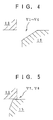
- Each of the variable orifices V1, V2, V3 and V4 is of center-open type, and the initial state (neutral state) of which is shown in FIG. 4.
- the second control portion 18 has four fluid paths which are connected to the pump 10, both fluid chambers 12A and 12B of the power cylinder 12 and the reservoir 11, and four variable orifices V5, V6, V7 and V8 are disposed in the middle of the fluid paths, respectively.
- Each of the variable orifices V5 and V6 communicating with the pump 10 is of center-open type, the same as the variable orifices V1-V4 of the first control portion 17.
- Each of the variable orifices V7 and V8 communicating with the reservoir 11 is of center-closed type, the initial state of which is shown in FIG. 5.
- the both fluid chambers 12A and 12B is communicated to a switching valve 20 which actuates in response to the difference pressure therebetween.
- the construction of the switching valve 20 is shown in FIG. 6 in detail.
- a spool 23 is slidably received in a housing and is normally maintained at the central position of the housing due to springs 24 and 25 interposed between the both ends of the spool 23 and the housing.
- the spool 23 has a pair of communication passages 28 and 29 communicating with each of the fluid chambers 12A and 12B.
- the housing is provided with two annular grooves 21 and 22 with a space in the longitudinal direction, which grooves are coupled to each other to communicate with the reservoir 11 through a drain passage 30.
- a first orifice 26 and a second orifice 27 are respectively formed between the spool 23 and the annular groove 21, and between the spool 23 and the annular groove 22.
- the pressure in the fluid chambers 12A and 12B are equal and the spool 23 is located at the central position of the housing.
- the fluid chamber 12A is communicated to the drain passage 30 through the communication passage 28 and the first orifice 26, while the fluid chambers 12B is communicated to the drain passage 30 through the communication passage 29 and the second orifice 27.
- a solenoid valve 32 having a control orifice 31 whose opening area is changed in accordance with a vehicle speed.
- a vehicle speed sensor 33 detects a vehicle speed and output a corresponding speed signal to an electronic controller 34.
- a current applied to the solenoid valve 32 is controlled by the electronic controller 34 in accordance with the vehicle speed within a range between values IA and IB. Referring to FIG. 7, the applied current is controlled to gradually decrease as the vehicle speed becomes high, whereby the opening area of the control orifice 31 is decreased. At a high vehicle speed, the applied current reaches to value IA to close the control orifice 31 of the solenoid valve 32.
- the pressurized fluid discharged from the pump 10 at the constant flow rate is supplied to the first and second control portions 17 and 18.
- the control orifice 31 of the solenoid valve 32 is fully opened.
- the center-closed variable orifices V7 and V8 of the second control portion 18 are closed and the center-open variable orifices V5 and V6 of the second control portion 18 are opened. Therefore, the both fluid chambers 12A and 12B of the power cylinder 12 are in communication with each other through the center-open variable orifices V5 and V6, and the pressures therein are maintained to be substantially same.
- the pressurized fluid discharged from the pump 10 is drained to the reservoir 11 through the center-open variable orifices V5 and V6, the two orifices 26 and 27 of the switching valve 20, and the control orifice 31 of the solenoid valve 32.
- the pressurized fluid supplied to the first control portion 17 is drained to the reservoir 11 through the center-open variable orifices V1-V4.
- the pressure in the right fluid chamber 12B of the power cylinder 12 is maintained to be low since the right fluid chamber 12B is communicated to the reservoir 11 through the control orifice 31 of the solenoid valve 32, while the left fluid chamber 12A is shut off from the reservoir 11 because the first orifice 26 of the switching valve 20 is closed.
- This causes the differential pressure between the both fluid chambers 12A and 12B, whereby the steering operation of the steering wheel 13 can be assisted.
- the differential pressure between the both fluid chambers 12A and 12B increases in accordance with the increase in the relative rotational angle of the rotary control valve 14. Therefore, the sufficiently power assisted steering operation can be always carried out when the steering wheel 13 is rotated at a low speed or stoppage of the vehicle.
- the control orifice 31 of the solenoid valve 32 is completely closed to shut off the two orifices 26 and 27 of the switching valve 20 from the reservoir 11.
- the opening areas of the center-open variable orifices V5 and V6 of the second control portion 18 are changed upon the rotation of the steering wheel 13, the differential pressure between the both fluid chambers 12A and 12B of the power cylinder 12 is maintained to be zero within a neutral zone that the relative rotational angle of the rotary control valve 14 is small, as illustrated by the dotted curved line in FIG. 8, because the both center-closed variable orifices V7 and V8 of the second control portion 18 remain in the closed state within the neutral zone.
- the steering feeling is the same as that in a manual steering apparatus, and the total rigidity against rotation of the steering wheel 13 around the neutral position, i.e., the resistance to turn the same can be increased.
- the pressurized fluid discharged from the pump 10 is drained to the reservoir 11 only through the first control portion 17.
- the differential pressure across the power cylinder 12 is generated in accordance with the relative rotational angle of the rotary control valve 14 when the steering wheel 13 is rotated at a low vehicle speed or stoppage of the vehicle. Therefore, the steering operation can be easily carried out even around the neutral position of the steering wheel 13.
- the differential pressure across the power cylinder 12 is maintained to be substantially zero when the steering wheel 13 is around the neutral position. Therefore, the driver can definitely feel the neutral position of the steering wheel 13, because the total rigidity of the steering wheel 13, i.e., the resistance to turn the same is enhanced around the neutral position.
- the differential pressure across the power cylinder 12 is generated in dependence upon the control characteristic of the rotary control valve 14.
Landscapes
- Engineering & Computer Science (AREA)
- Chemical & Material Sciences (AREA)
- Combustion & Propulsion (AREA)
- Transportation (AREA)
- Mechanical Engineering (AREA)
- Steering Control In Accordance With Driving Conditions (AREA)
- Power Steering Mechanism (AREA)
Claims (5)
- Servolenkung mit einer Fluidquelle (10) zum Zuführen von unter Druck gesetztem Fluid, einem Servozylinder (12), der ein Paar Fluidkammern (12A, 12B) aufweist und betreibbar ist, um eine Unterstützungskraft zu erzeugen, einem Steuerventil (14), das auf die Betätigung eines Lenkrades (13) anspricht, zum Steuern des Stroms von unter Druck gesetztem Fluid von der Fluidquelle (10) zu einem Reservoir (11) und zu den Fluidkammern (12A, 12B) des Servozylinders (12), worin das Steuerventil (14) aufweist:einen ersten Steuerabschnitt (17), der vom Servozylinder (12) fluidmäßig getrennt ist und einen ersten variablen Öffnungsmechanismus (V1-V4) enthält, der gestattet, daß Fluid von der Fluidquelle (10) zum Reservoir (11) strömt, wenn das Lenkrad (13) bei der Neutralstellung ist; undeinen zweiten Steuerabschnitt (18), der mit dem Servozylinder (12) fluidmäßig verbunden ist und zwei Zufuhrwege, die die Fluidquelle (10) jeweils mit den Fluidkammern (12A, 12B) des Servozylinders (12) verbinden, zwei Ablaßwege, die die Fluidkammern (12A, 12B) des Servozylinders (12) jeweils mit dem Reservoir (11) verbinden, und einen zweiten variablen Öffnungsmechanismus enthält,
dadurch gekennzeichnet, daß der zweite variable Öffnungsmechanismus gestattet, daß Fluid von der Fluidquelle (10) den Fluidkammern (12A, 12B) des Servozylinders (12) zugeführt wird, während im wesentlichen verhindert wird, daß Fluid von den Fluidkammern (12A, 12B) des Servozylinders (12) zu dem Reservoir (11) strömt, wenn das Lenkrad (13) bei der Neutralstellung ist, und die Servolenkung ferner mit einem Ablaßsteuermechanismus versehen ist, der auf einen Differenzdruck zwischen den Fluidkammern (12A, 12B) des Servozylinders (12) anspricht, um die Verbindung von einer der Fluidkammern (12A, 12B) unter hohem Druck mit dem Reservoir (11) zu steuern, und auf eine Fahrzeuggeschwindigkeit anspricht, um die Verbindung der Fluidkammern (12A, 12B) mit dem Reservoir (11) zu steuern. - Servolenkung nach Anspruch 1, dadurch gekennzeichnet, dar der Ablaßsteuermechanismus als Antwort auf den Differenzdruck der Fluidkammern (12A, 12B) des Servozylinders (12) betätigt wird, um zu verhindern, daß eine der Fluidkammern (12A, 12B) unter hohem Druck mit dem Reservoir (11) in Verbindung steht.
- Servolenkung nach Anspruch 1, dadurch gekennzeichnet, daß:jede der Fluidkammern (12A, 12B) des Servozylinders (12) durch den Ablaßsteuermechanismus mit dem Reservoir (11) in Verbindung steht; undder Ablaßsteuermechanismus eine Schalteinrichtung (20), die mit den Fluidkammern (12A, 12B) des Servozylinders (12) in Verbindung steht, um gemäß dem Differenzdruck dazwischen betätigt zu werden, und eine Ventileinrichtung (32) mit einer Steueröffnung (31) aufweist, deren Öffnungsfläche gemäß der Fahrzeuggeschwindigkeit geändert wird.
- Servolenkung nach Anspruch 3, dadurch gekennzeichnet, daß:die Ventileinrichtung (32) ein durch ein Fahrzeuggeschwindigkeitssignal gesteuertes Solenoidventil aufweist; unddie Steueröffnung (31) der Ventileinrichtung (32) bei einer niedrigen Fahrzeuggeschwindigkeit geöffnet und bei einer hohen Fahrzeuggeschwindigkeit geschlossen wird.
- Servolenkung nach Anspruch 3, dadurch gekennzeichnet, daß:die Schalteinrichtung (20) zwei variable Öffnungen (26, 27) aufweist, die jeweils auf zwei Fluiddurchgängen (28, 29) gebildet sind, die die Fluidkammern (12A, 12B) des Servozylinders (12) und die Ventileinrichtung (32) verbinden; undeine der beiden variablen Öffnungen (26, 27), die auf dem Fluiddurchgang (28, 29) gebildet ist, der die Fluidkammer (12A, 12B) unter höherem Druck verbindet, als Antwort auf den Differenzdruck zwischen den Fluidkammern (12A, 12B) des Servozylinders (12) geschlossen wird.
Applications Claiming Priority (2)
| Application Number | Priority Date | Filing Date | Title |
|---|---|---|---|
| JP13165394A JP3368666B2 (ja) | 1994-06-14 | 1994-06-14 | 動力舵取装置 |
| JP131653/94 | 1994-06-14 |
Publications (2)
| Publication Number | Publication Date |
|---|---|
| EP0687616A1 EP0687616A1 (de) | 1995-12-20 |
| EP0687616B1 true EP0687616B1 (de) | 1998-11-11 |
Family
ID=15063090
Family Applications (1)
| Application Number | Title | Priority Date | Filing Date |
|---|---|---|---|
| EP95109120A Expired - Lifetime EP0687616B1 (de) | 1994-06-14 | 1995-06-13 | Servolenkung |
Country Status (4)
| Country | Link |
|---|---|
| US (1) | US5538095A (de) |
| EP (1) | EP0687616B1 (de) |
| JP (1) | JP3368666B2 (de) |
| DE (1) | DE69505892T2 (de) |
Families Citing this family (5)
| Publication number | Priority date | Publication date | Assignee | Title |
|---|---|---|---|---|
| JP3240866B2 (ja) * | 1995-01-19 | 2001-12-25 | 豊田工機株式会社 | 動力舵取装置 |
| DE19705382A1 (de) * | 1996-02-13 | 1997-08-14 | Unisia Jecs Corp | Hilfskrafteinheit für eine Lenkanlage |
| JP2000159130A (ja) * | 1998-11-30 | 2000-06-13 | Koyo Seiko Co Ltd | 油圧制御弁及びこれを用いた動力舵取装置 |
| US6484841B2 (en) * | 1999-12-13 | 2002-11-26 | Kayaba Industry Co., Ltd. | Power steering |
| JP2001301633A (ja) | 2000-04-25 | 2001-10-31 | Showa Corp | 車両用流体圧式パワーステアリング装置 |
Family Cites Families (3)
| Publication number | Priority date | Publication date | Assignee | Title |
|---|---|---|---|---|
| WO1990002070A1 (de) * | 1988-08-26 | 1990-03-08 | Zahnradfabrik Friedrichshafen Ag | Hilfskraftlenkung |
| EP0594137B1 (de) * | 1992-10-22 | 1998-07-29 | Toyoda Koki Kabushiki Kaisha | Hydraulische Servolenkung |
| JP2932907B2 (ja) * | 1993-11-12 | 1999-08-09 | 豊田工機株式会社 | 動力舵取装置 |
-
1994
- 1994-06-14 JP JP13165394A patent/JP3368666B2/ja not_active Expired - Fee Related
-
1995
- 1995-06-13 DE DE69505892T patent/DE69505892T2/de not_active Expired - Fee Related
- 1995-06-13 EP EP95109120A patent/EP0687616B1/de not_active Expired - Lifetime
- 1995-06-13 US US08/489,837 patent/US5538095A/en not_active Expired - Fee Related
Also Published As
| Publication number | Publication date |
|---|---|
| JPH07329812A (ja) | 1995-12-19 |
| EP0687616A1 (de) | 1995-12-20 |
| DE69505892T2 (de) | 1999-04-01 |
| JP3368666B2 (ja) | 2003-01-20 |
| US5538095A (en) | 1996-07-23 |
| DE69505892D1 (de) | 1998-12-17 |
Similar Documents
| Publication | Publication Date | Title |
|---|---|---|
| EP0594137B1 (de) | Hydraulische Servolenkung | |
| US7086494B2 (en) | Power steering system | |
| US5224564A (en) | Hydrostatic power steering system | |
| US5439070A (en) | Hydraulic power steering apparatus | |
| US4860846A (en) | Vehicle speed responsive variable assist power steering system | |
| GB2311047A (en) | Flow controlling apparatus for power steering system | |
| US5184693A (en) | Vehicle hydraulic power steering system | |
| US4884648A (en) | Variable assist power steering system with varying power assist characteristic | |
| EP0658468B1 (de) | Hydraulische Servolenkung | |
| EP0653342B1 (de) | Hydraulische Servolenkung | |
| JPS61247575A (ja) | 動力舵取装置の操舵力制御装置 | |
| EP0687616B1 (de) | Servolenkung | |
| US4875542A (en) | Hydraulic system for variable assist power steering system | |
| US4862985A (en) | Variable assist power steering system with varying power assist with vehicle speed | |
| US4905784A (en) | Power-assisted steering system for automotive vehicle | |
| US5207780A (en) | Hydraulic valve device for automotive power steering gear | |
| US5329766A (en) | Hydraulic power steering system with input detection capability | |
| US6035760A (en) | Power steering system | |
| EP0689985B1 (de) | Servolenkung | |
| US5823090A (en) | Power steering apparatus having an easily adjustable counter force mechanism | |
| JPH04368286A (ja) | 車両の舵取り装置 | |
| KR0154657B1 (ko) | 유량제어식 전자제어 파워스티어링 장치 | |
| JPS59134064A (ja) | パワ−ステアリングのロ−タリ型作動弁装置 | |
| JPH08127354A (ja) | パワーステアリング装置 | |
| JPH0619420Y2 (ja) | 動力舵取装置の操舵力制御装置 |
Legal Events
| Date | Code | Title | Description |
|---|---|---|---|
| PUAI | Public reference made under article 153(3) epc to a published international application that has entered the european phase |
Free format text: ORIGINAL CODE: 0009012 |
|
| AK | Designated contracting states |
Kind code of ref document: A1 Designated state(s): DE FR GB |
|
| RIN1 | Information on inventor provided before grant (corrected) |
Inventor name: MORI, KATSUHISA Inventor name: SUZUKI, MIKIO Inventor name: HAGA, KYOSUKE |
|
| 17P | Request for examination filed |
Effective date: 19960620 |
|
| 17Q | First examination report despatched |
Effective date: 19970418 |
|
| GRAG | Despatch of communication of intention to grant |
Free format text: ORIGINAL CODE: EPIDOS AGRA |
|
| GRAG | Despatch of communication of intention to grant |
Free format text: ORIGINAL CODE: EPIDOS AGRA |
|
| GRAH | Despatch of communication of intention to grant a patent |
Free format text: ORIGINAL CODE: EPIDOS IGRA |
|
| GRAH | Despatch of communication of intention to grant a patent |
Free format text: ORIGINAL CODE: EPIDOS IGRA |
|
| GRAA | (expected) grant |
Free format text: ORIGINAL CODE: 0009210 |
|
| AK | Designated contracting states |
Kind code of ref document: B1 Designated state(s): DE FR GB |
|
| REF | Corresponds to: |
Ref document number: 69505892 Country of ref document: DE Date of ref document: 19981217 |
|
| ET | Fr: translation filed | ||
| PLBE | No opposition filed within time limit |
Free format text: ORIGINAL CODE: 0009261 |
|
| STAA | Information on the status of an ep patent application or granted ep patent |
Free format text: STATUS: NO OPPOSITION FILED WITHIN TIME LIMIT |
|
| 26N | No opposition filed | ||
| REG | Reference to a national code |
Ref country code: GB Ref legal event code: IF02 |
|
| PGFP | Annual fee paid to national office [announced via postgrant information from national office to epo] |
Ref country code: DE Payment date: 20080619 Year of fee payment: 14 |
|
| PGFP | Annual fee paid to national office [announced via postgrant information from national office to epo] |
Ref country code: FR Payment date: 20080617 Year of fee payment: 14 |
|
| PGFP | Annual fee paid to national office [announced via postgrant information from national office to epo] |
Ref country code: GB Payment date: 20080618 Year of fee payment: 14 |
|
| GBPC | Gb: european patent ceased through non-payment of renewal fee |
Effective date: 20090613 |
|
| REG | Reference to a national code |
Ref country code: FR Ref legal event code: ST Effective date: 20100226 |
|
| PG25 | Lapsed in a contracting state [announced via postgrant information from national office to epo] |
Ref country code: FR Free format text: LAPSE BECAUSE OF NON-PAYMENT OF DUE FEES Effective date: 20090630 |
|
| PG25 | Lapsed in a contracting state [announced via postgrant information from national office to epo] |
Ref country code: GB Free format text: LAPSE BECAUSE OF NON-PAYMENT OF DUE FEES Effective date: 20090613 |
|
| PG25 | Lapsed in a contracting state [announced via postgrant information from national office to epo] |
Ref country code: DE Free format text: LAPSE BECAUSE OF NON-PAYMENT OF DUE FEES Effective date: 20100101 |