EP0687787A1 - Dispositif de charnière - Google Patents
Dispositif de charnière Download PDFInfo
- Publication number
- EP0687787A1 EP0687787A1 EP95107122A EP95107122A EP0687787A1 EP 0687787 A1 EP0687787 A1 EP 0687787A1 EP 95107122 A EP95107122 A EP 95107122A EP 95107122 A EP95107122 A EP 95107122A EP 0687787 A1 EP0687787 A1 EP 0687787A1
- Authority
- EP
- European Patent Office
- Prior art keywords
- hinge
- band
- pivot axis
- receiving element
- hinge device
- Prior art date
- Legal status (The legal status is an assumption and is not a legal conclusion. Google has not performed a legal analysis and makes no representation as to the accuracy of the status listed.)
- Granted
Links
- 238000006073 displacement reaction Methods 0.000 description 1
- 238000000034 method Methods 0.000 description 1
- 238000003801 milling Methods 0.000 description 1
Images

Classifications
-
- E—FIXED CONSTRUCTIONS
- E05—LOCKS; KEYS; WINDOW OR DOOR FITTINGS; SAFES
- E05D—HINGES OR SUSPENSION DEVICES FOR DOORS, WINDOWS OR WINGS
- E05D7/00—Hinges or pivots of special construction
- E05D7/04—Hinges adjustable relative to the wing or the frame
- E05D7/0415—Hinges adjustable relative to the wing or the frame with adjusting drive means
- E05D7/0423—Screw-and-nut mechanisms
-
- E—FIXED CONSTRUCTIONS
- E05—LOCKS; KEYS; WINDOW OR DOOR FITTINGS; SAFES
- E05D—HINGES OR SUSPENSION DEVICES FOR DOORS, WINDOWS OR WINGS
- E05D3/00—Hinges with pins
- E05D3/02—Hinges with pins with one pin
- E05D2003/025—Hinges with pins with one pin having three knuckles
-
- E—FIXED CONSTRUCTIONS
- E05—LOCKS; KEYS; WINDOW OR DOOR FITTINGS; SAFES
- E05D—HINGES OR SUSPENSION DEVICES FOR DOORS, WINDOWS OR WINGS
- E05D7/00—Hinges or pivots of special construction
- E05D7/04—Hinges adjustable relative to the wing or the frame
- E05D2007/0461—Hinges adjustable relative to the wing or the frame in angular arrangement to the wing or the frame
-
- E—FIXED CONSTRUCTIONS
- E05—LOCKS; KEYS; WINDOW OR DOOR FITTINGS; SAFES
- E05D—HINGES OR SUSPENSION DEVICES FOR DOORS, WINDOWS OR WINGS
- E05D7/00—Hinges or pivots of special construction
- E05D7/04—Hinges adjustable relative to the wing or the frame
- E05D2007/0469—Hinges adjustable relative to the wing or the frame in an axial direction
-
- E—FIXED CONSTRUCTIONS
- E05—LOCKS; KEYS; WINDOW OR DOOR FITTINGS; SAFES
- E05D—HINGES OR SUSPENSION DEVICES FOR DOORS, WINDOWS OR WINGS
- E05D7/00—Hinges or pivots of special construction
- E05D7/04—Hinges adjustable relative to the wing or the frame
- E05D2007/0476—Pocket hinges
-
- E—FIXED CONSTRUCTIONS
- E05—LOCKS; KEYS; WINDOW OR DOOR FITTINGS; SAFES
- E05D—HINGES OR SUSPENSION DEVICES FOR DOORS, WINDOWS OR WINGS
- E05D7/00—Hinges or pivots of special construction
- E05D7/04—Hinges adjustable relative to the wing or the frame
- E05D2007/0484—Hinges adjustable relative to the wing or the frame in a radial direction
-
- E—FIXED CONSTRUCTIONS
- E05—LOCKS; KEYS; WINDOW OR DOOR FITTINGS; SAFES
- E05Y—INDEXING SCHEME ASSOCIATED WITH SUBCLASSES E05D AND E05F, RELATING TO CONSTRUCTION ELEMENTS, ELECTRIC CONTROL, POWER SUPPLY, POWER SIGNAL OR TRANSMISSION, USER INTERFACES, MOUNTING OR COUPLING, DETAILS, ACCESSORIES, AUXILIARY OPERATIONS NOT OTHERWISE PROVIDED FOR, APPLICATION THEREOF
- E05Y2900/00—Application of doors, windows, wings or fittings thereof
- E05Y2900/10—Application of doors, windows, wings or fittings thereof for buildings or parts thereof
- E05Y2900/13—Type of wing
- E05Y2900/132—Doors
Definitions
- the invention relates to a hinge device with a pivot axis, a frame or frame-side hinge part, or the like on a frame, a frame.
- a door can be fastened, a hinge receiving element, which can be fastened to a door leaf of the door, and a hinge hinge, which is held on the one hand pivotably about the pivot axis and on the other hand can be fixed in the hinge receiving element.
- the hinge band In known hinge devices of this type, the hinge band must first be fixed within the band receiving element in the directions parallel to its width and length in order to mount it. In order to achieve this, the hinge band is inserted into the band receiving element in such a way that the hinge band is correctly positioned in the plane determined by its width and length. Then the hinge band or the like by clamping. fixed in the tape receiving element. For this comparatively complicated assembly of the hinge band within the hinge receiving element, since the hinge receiving element is already inside the door leaf and because the hinge band already on the pivot axis with the frame or frame-side hinge part and thus the frame, the frame or the like.
- the holder by means of which the hinge band is now held in the band receiving element, is in turn adjustable within the band receiving element in a direction approximately perpendicular to the plane of the hinge band. This so-called depth adjustment of this bracket and thus of the hinge and thus of the door wing is then carried out, for example, by means of two screws acting on the bracket mentioned.
- the invention has for its object to provide a hinge device of the type described, its assembly by a single person is possible without great problems and which also has the same milling depth as the standardized hinge devices known from the prior art.
- the hinge band is pivotally fixed in its end portion distant from the pivot axis in the band receiving element. Due to such a tiltable mounting of the hinge band within the band receiving element, the so-called "floating" mounting of the hinge band within the band receiving element previously used in the prior art can be dispensed with, only the tilting angle of the hinge band within for displacing the pivot axis of the hinge device in the thickness direction of the hinge band of the tape receiving element must be adjusted.
- a tiltable yet fixed mounting of the end portion of the hinge strap remote from the pivot axis can be achieved within the strap receiving element if the end portion of the hinge strap remote from the pivot axis is arranged in a bearing slot, the width of which on its opening surface near the pivot axis corresponds to the thickness of the hinge strap and which is directed in the direction of its end surface remote from the pivot axis is expanded.
- the hinge band can be tilted in one direction around the one opening edge of the opening surface of the bearing slot near the pivot axis and in the other direction around the other opening edge of the opening surface of the bearing slot near the pivot axis.
- the above-mentioned opening edges of the opening surface close to the swivel axis are, of course, its longitudinal edges extending in the vertical direction.
- a flat contact between the end section of the hinge band remote from the pivot axis and the respective wall surface of the bearing slot can be achieved if the bearing slot widens linearly on its two longitudinal sides.
- the hinge band or its end section remote from the pivot axis can be fixed in the band receiving element or in the bearing slot in a structurally less complex manner if at least two fixing pins are formed on the end section of the hinge band remote from the pivot axis, which engage in recesses formed in the band receiving element or in the bearing slot. In this way, a fixation of the hinge strap in its width direction is achieved in a simple manner, without impairing its tiltability.
- the hinge band can be brought into different vertical positions in relation to the band receiving element or to its bearing slot, the fixing pins moving upwards or downwards in the recesses designed as elongated holes.
- the tilting of the hinge band can be effected in a metered manner and with fine gradations if the hinge band can be tilted by means of a tilt angle adjustment screw within the band receiving element about a tilting point formed on its end section remote from the pivot axis.
- This tilting point which is the one opening edge of the opening surface of the bearing slot near the pivot axis in the one direction and the other opening edge of the opening surface of the bearing slot near the pivot axis, consequently changes depending on the tilt direction of the hinge band.
- the rotation of the tilt angle adjustment screw can be implemented particularly effectively and in a finely metered manner in a change in the tilt angle of the hinge strap if the tilt angle adjustment screw is in engagement with a thread formed in the hinge strap and can be actuated through an opening in the housing of the strap receiving element.
- the hinge strap is connected at a vertical end section to an adjusting spindle, which is rotatably and vertically adjustable in a thread arranged fixedly on the band receiving element and is rotatable and therefore vertically adjustable by means of a high / low adjusting screw.
- the vertical adjustment of the hinge strap within the strap receiving element thus takes place via a spindle gear which is formed from the adjusting spindle which is connected to the hinge strap and the thread which is fixedly arranged on the strap receiving element and which is driven by the high / low adjusting screw.
- An effective engagement between the adjusting spindle and the up / down adjusting screw can be achieved in a mechanically simple manner if the adjusting spindle has a toothed ring with which the up / down adjusting screw is engaged over the entire vertical adjustment stroke of the adjusting spindle.
- a vertical fixation of the adjusting spindle with respect to the hinge band can be achieved in a structurally simple manner, if in the vertical end section of the hinge band a recess provided with an extension is formed, into which a connecting section of the adjusting spindle engages, expediently a positive engagement of the connecting section of the adjusting spindle in the recess provided with the extension is provided in the vertical end section of the hinge band.
- a faster upward or downward movement of the hinge band within the band receiving element is to take place at the same rotational speed of the up / down adjusting screw, it is expedient if a nut is arranged on the vertical end section of the hinge band, into which a separate threaded section of the adjusting spindle engages, whereby the direction of the pitch of the separate threaded section of the adjusting spindle and the nut arranged on the vertical end section of the hinge band is opposite to the direction of the pitch of the thread fixed on the band receiving element.
- the vertical end section of the hinge strap connected to the adjusting spindle is arranged at the upper end of the hinge strap, in which case the thread of the spindle gear consisting of the adjusting spindle and the thread is fixed above the hinge strap in the strap receiving element.
- the positioning of the hinge strap in relation to the strap receiving element can be effected by means of successive tilt angle changes in any order which the tilt angle of the hinge band is varied within the band receiving element, and vertical adjustments in which the vertical position of the hinge band within the band receiving element is changed by means of the up / down adjusting screw and the described spindle gear.
- a change in the tilt angle it is readily possible for a change in the tilt angle, a change in the vertical adjustment of the hinge band and then a change in the tilt angle of the hinge band, etc.
- the hinge device described above can expediently be used as part of a hinge having at least two hinge devices, the other hinge device not having to be equipped with the spindle gear required for the vertical adjustment of the hinge band.
- a hinge that can be assembled in a simple manner for connecting a door leaf to a frame, a frame or the like. can be reached if the hinge device described above is arranged as the middle hinge device of a hinge having three hinge devices.
- the so-called depth adjustment can be carried out in all three hinge devices, the vertical adjustment of the door frame being carried out only by means of the middle hinge device, the hinge band of which can be adjusted in the vertical direction with respect to its band receiving element.
- the vertical forces are derived in each case via only one hinge device of a hinge having a plurality of hinge devices.
- the present invention can be used in an analogous manner in hinge devices in which a pivot axis, a door leaf-side hinge part which can be fastened to a door leaf of a door and is pivotably mounted about the pivot axis on the latter, a band receiving element which is attached to a frame, a frame or the like. the like the door can be fastened, and a hinge band is provided which is held on the one hand on the swivel axis and on the other hand can be fixed in the band receiving element.
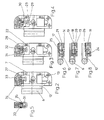
- a hinge shown in Figure 1 is used to attach a door wing 2 shown only partially to a frame, a frame 1 or the like. It must be taken into account here that the door leaf 2 must be pivotably mounted with respect to the frame or frame 1, so that the opening of the frame or frame 1 can be closed and released by means of it.
- the frame or the frame 1 is only partially - like the door leaf 2 - shown.
- the hinge shown in FIG. 1 has three hinge devices 3, 4, 5, the pivot axes 6 of which, for the hinge device 4 shown in FIG. 1 in FIGS. 2 to 4 and in FIGS. 6 to 8, are aligned.
- the door leaf 2 can be pivoted with respect to the frame or the frame 1 about these pivot axes 6.
- the hinge device 4 arranged in the center in FIG. 1 has a hinge part 8 which is fixedly attached to the frame or to the frame 1 by means of screws 9.
- the hinge part 8 is also connected to the pivot axis 6.
- the frame or frame-side hinge part 8 has two bearing sections 10, between which a bearing section 11 of a hinge band 12 is pivotally mounted about the pivot axis 6, the hinge band 12 having a band tab 13 which is held within the band receiving element 7 in the manner described below.
- the band receiving element 7 has a housing 14 which has an opening slot 15 on its side opposite the pivot axis 6, through which the band tab 13 of the hinge band 12 projects into the band receiving element 7.
- the width of the opening slot 15 is considerably larger than the thickness of the band tab 13, so that the band tab 13 can be moved to the band receiving element 7 to the extent determined by the width of the opening slot 15.
- a bearing slot 16 is formed therein, in which the hinge band 12 or the band tab 13 sits with its end section 17 remote from the pivot axis.
- the bearing slot 16 has an opening surface 18 near the pivot axis, the width of which corresponds to the thickness of the band tab 13. Behind its opening surface 18 near the pivot axis, the bearing slot 16 widens linearly on its two longitudinal sides 19, 20 so that it is wider at its end surface 21 remote from the pivot axis than the thickness of the hinge flap 13. Therefore, the hinge flap 13 is in one direction around the one longitudinal edge of the near the pivot axis Opening surface 18 and in the other direction around the other longitudinal edge of the opening surface 18 near the pivot axis tiltable.
- the linear extension of the long side 19 or that of the long side 20 of the bearing slot 16 is selected such that the hinge flap 13 bears against the upper edge of the opening slot 15 in FIG. 8 when the end section of the hinge flap 13 remote from the pivot axis against the lower long side 20 in FIG. 8 abuts, and that the hinge flap 13 abuts against the lower edge of the opening slot 15 in FIG. 8 when the end section 17 of the hinge flap 13 remote from the pivot axis rests against the upper longitudinal side 19 of the bearing slot 16 in FIG.
- the end portion 17 of the hinge flap 13 remote from the pivot axis is held within the bearing slot 16 by fixing pins 22 which engage in recesses in the form of elongated holes 23, which are formed on a longitudinal side 19, 20 of the bearing slot 16.
- the elongated holes 23 extend with their length dimensions parallel to the pivot axis 6, so that the hinge band 12 is slidably supported along the pivot axis 6 within the band receiving element 7 or the bearing slot 6.
- the band tab 13 has a thread 24 in which a tilt angle adjustment screw 25 is seated, which can be actuated through an opening 26 in the housing 14 of the band receiving element 7.
- the tilt angle adjusting screw 25, the thread 24 and the opening 26 are close to the opening slot 15 of the housing.
- the hinge flap 13 moves during rotation of the tilt angle adjustment screw 25 between the end positions shown in FIGS. 6 and 8, in which the end section 17 of the hinge flap 13 remote from the pivot axis abuts one side on the upper 19 or the lower longitudinal side 20 of the bearing slot 16.
- a so-called “depth adjustment” of the hinge band 12 can thus be accomplished.
- the lower and upper hinge devices 3, 5 in FIG. 1 also have the above-described features with reference to the hinge device 4 shown in FIG. 1.
- the hinge device 4 in FIG. 1 differs from the other hinge devices 3, 5 by the features specified below, which are used for the vertical adjustment of the hinge band 12 within the band receiving element 7.
- the band tab 13 has a recess 28 which has an extension 29 at its end oriented towards the center of the band tab.
- a connecting section 30 of an adjusting spindle 31 is seated in this recess.
- the connecting section 30 is in cross section designed so that it sits positively within the extension 29 having the recess 28, with the result that when the connecting portion 30 is also the hinge flap 13 and thus the hinge band 12 are moved in the vertical direction within the band receiving element 7, this movement by the Elongated holes 23 in which the fixing pins 22 formed on the end section 17 of the hinge flap remote from the pivot axis are limited.
- the adjusting spindle 31 is mounted parallel to the swivel axis 6 within the band receiving element 7 and is rotatable and adjustable in its axial position in a thread 32 fixedly arranged on the band receiving element 7.
- the adjusting spindle 31 has between its connecting section 30 and the thread 32 fixedly arranged on the tape receiving element 7 a ring gear 33 which is in engagement with a high / low adjusting screw 34 which can be actuated through an opening 35 in the housing 14 of the tape receiving element 7.
- the adjustment spindle 31 When the up / down adjustment screw 34 rotates, the adjustment spindle 31 is rotated due to the engagement between the up / down adjustment screw 34 and the ring gear 33. Since the adjusting spindle 31 is in threaded engagement with the thread 32 arranged fixedly on the band receiving element 7, the adjusting spindle 31 is moved parallel to the pivot axis 6 due to its rotation within the band receiving element 7, which means parallel to the vertical direction in the exemplary embodiment shown.
- the hinge flap 13 With the connecting section 30 of the adjusting spindle 31, the hinge flap 13 also moves, so that the hinge band 12 moves along the pivot axis 6.
- the desired vertical position of the hinge band 12 within the band receiving element 7 can thus be selected in a simple manner.
- the adjustment of the hinge strap 12 parallel to the pivot axis 6 can be interrupted at any time in order to change the depth adjustment of the hinge strap 12 within the strap receiving element by actuating the tilt angle adjustment screw 25 in the desired direction.
- the adjustment of the tilt angle adjustment screw 25 can also be interrupted at any time in order to again vary the position of the hinge band 12 in the longitudinal direction of the pivot axis 6.
- the entire setting of the hinge band 12 within the band receiving element and thus the entire setting of the relative position between the door leaf 2 and frame 1 can be carried out by a single person.
Landscapes
- Engineering & Computer Science (AREA)
- Mechanical Engineering (AREA)
- Hinges (AREA)
- Pivots And Pivotal Connections (AREA)
Applications Claiming Priority (2)
| Application Number | Priority Date | Filing Date | Title |
|---|---|---|---|
| DE4421056 | 1994-06-17 | ||
| DE4421056A DE4421056C2 (de) | 1994-06-17 | 1994-06-17 | Scharniereinrichtung |
Publications (2)
| Publication Number | Publication Date |
|---|---|
| EP0687787A1 true EP0687787A1 (fr) | 1995-12-20 |
| EP0687787B1 EP0687787B1 (fr) | 1998-03-04 |
Family
ID=6520743
Family Applications (1)
| Application Number | Title | Priority Date | Filing Date |
|---|---|---|---|
| EP95107122A Expired - Lifetime EP0687787B1 (fr) | 1994-06-17 | 1995-05-11 | Dispositif de charnière |
Country Status (4)
| Country | Link |
|---|---|
| US (1) | US5701636A (fr) |
| EP (1) | EP0687787B1 (fr) |
| DE (1) | DE4421056C2 (fr) |
| ES (1) | ES2116008T3 (fr) |
Cited By (2)
| Publication number | Priority date | Publication date | Assignee | Title |
|---|---|---|---|---|
| EP1749957A3 (fr) * | 2005-08-02 | 2009-07-01 | Simonswerk, Gesellschaft mit beschränkter Haftung | Réceptacle de charnière pour cadre à profilés creux |
| EP2981663A4 (fr) * | 2013-04-04 | 2016-11-02 | Schlage Lock Co Llc | Charnière réglable |
Families Citing this family (38)
| Publication number | Priority date | Publication date | Assignee | Title |
|---|---|---|---|---|
| US6353967B1 (en) | 1998-09-02 | 2002-03-12 | Francisco A. Escobar | Ninety-degree door hinge |
| DE19851165A1 (de) * | 1998-11-06 | 2000-05-18 | Simonswerk Gmbh | Türscharnier |
| US6998005B2 (en) * | 2001-03-29 | 2006-02-14 | Fresco Plastics Llc | Method and apparatus for forming dye sublimation images in solid plastic |
| EP1413700A3 (fr) * | 2002-10-24 | 2006-03-15 | Harald Sitter | Charnière pour portes et autres éléments de construction |
| US20040128794A1 (en) * | 2003-01-02 | 2004-07-08 | Stanley Chung | Adjustable hinge |
| SE529138C2 (sv) * | 2004-02-09 | 2007-05-08 | Assa Ab | Gångled |
| US7346959B2 (en) * | 2004-02-27 | 2008-03-25 | Newell Operating Company | Hinge |
| US7293329B2 (en) * | 2004-02-27 | 2007-11-13 | Newell Operating Company | Vertically adjustable hinge |
| US7331085B2 (en) | 2004-02-27 | 2008-02-19 | Newell Operating Company | Horizontally adjustable hinge |
| US7334293B2 (en) * | 2005-02-16 | 2008-02-26 | Newell Operating Company | Vertically adjustable hinge |
| US20060225250A1 (en) * | 2005-04-06 | 2006-10-12 | Noubar Yeremlan | Hinge system for storm door |
| US7571516B2 (en) * | 2005-08-02 | 2009-08-11 | Simonswerk, Gesellschaft mit beschränkter Haftung | Hinge-plate accommodation element for attaching a hinge plate |
| US7676887B2 (en) * | 2005-12-22 | 2010-03-16 | Stanley Chung | Two-stage adjustable door hinge |
| US7552511B2 (en) * | 2006-07-28 | 2009-06-30 | Creative Research & Development, Inc. | Adjustable hinge |
| WO2008056268A2 (fr) * | 2006-11-06 | 2008-05-15 | Hoppe North America, Inc. | Ensemble de charnière à réglage pour installation par un gaucher ou un droitier |
| US20080104798A1 (en) * | 2006-11-06 | 2008-05-08 | Christoph Hoppe | Adjustable Hinge Set |
| US20080244866A1 (en) * | 2007-04-09 | 2008-10-09 | Stanley Michael W | Special improved adjustable hinge device |
| DE102007019938B3 (de) | 2007-04-27 | 2008-03-27 | Simonswerk, Gmbh | Türband |
| DE102008003557B4 (de) * | 2008-01-09 | 2015-02-26 | Eco Schulte Gmbh & Co. Kg | Höhenverstellbares Türband mit antreibenden Zahnrädern |
| CA2697693C (fr) | 2009-03-25 | 2018-01-02 | Amesbury Group, Inc. | Charniere de porte reglable |
| US8490246B2 (en) * | 2009-03-26 | 2013-07-23 | Truth Hardware Corporation | Adjustable hinge |
| DE102010011326B3 (de) * | 2010-03-13 | 2011-06-16 | Simonswerk, Gesellschaft mit beschränkter Haftung | Türband, insbesondere für Gebäudeabschlusstüren |
| US8863358B2 (en) * | 2012-06-14 | 2014-10-21 | SZ Contracting, LLC | Adjustable hinge |
| US20140096450A1 (en) * | 2012-10-10 | 2014-04-10 | Masonite Corporation | Door assembly |
| KR102030845B1 (ko) * | 2012-11-13 | 2019-10-11 | 삼성전자주식회사 | 냉장고 및 이에 구비되는 하부힌지모듈 |
| ITVR20130127A1 (it) * | 2013-05-27 | 2014-11-28 | Ind Casearia Silvio Belladell I S R L | Sistema a cerniere |
| CN103452406B (zh) * | 2013-09-09 | 2016-01-13 | 联程机械(宁波)有限公司 | 一种可调节的门窗铰链系统 |
| US9617782B2 (en) | 2014-08-07 | 2017-04-11 | Truth Hardware Corporation | Self-sealing butt hinge |
| US10246916B1 (en) | 2015-05-12 | 2019-04-02 | Tyler L. Kessler | Door hinges and method for rehanging a door to realign the door in relation to a door jamb |
| US10760310B2 (en) | 2015-05-12 | 2020-09-01 | Tyler Kessler Holdings Inc. | Replacement door hinges for aligning a door in relation to a door jamb |
| DE102015116192B3 (de) * | 2015-09-24 | 2016-04-14 | Simonswerk, Gesellschaft mit beschränkter Haftung | Bandaufnahmeteil für ein verdeckt liegendes Bandsystem für Türen oder Fenster und Türband mit dem Bandaufnahmeteil |
| US10174533B2 (en) * | 2016-03-10 | 2019-01-08 | At&T Intellectual Property I, L.P. | Hinge |
| US20180068543A1 (en) * | 2016-09-06 | 2018-03-08 | Bi Incorporated | Systems and Methods for Fitting a Tracking Device to a Limb |
| AT519666B1 (de) * | 2017-11-24 | 2018-09-15 | Blum Gmbh Julius | Möbelbeschlag |
| AU2017279738B1 (en) | 2017-12-21 | 2018-08-30 | Assa Abloy New Zealand Limited | Multi panel components |
| US10844898B1 (en) | 2018-06-27 | 2020-11-24 | Orbit Irrigation Products, Llc | Adjustable bracket assembly |
| US11952833B1 (en) * | 2019-09-11 | 2024-04-09 | Larson Manufacturing Company Of South Dakota, Llc | Building systems and methods for installing building systems relative to building openings |
| US11859426B2 (en) | 2020-10-07 | 2024-01-02 | Kohler Co. | Hinge assembly |
Citations (5)
| Publication number | Priority date | Publication date | Assignee | Title |
|---|---|---|---|---|
| DE1276500B (de) * | 1960-12-06 | 1968-08-29 | Therma Ag | Verstellbares Scharnier fuer Schranktueren od. dgl. |
| FR2392206A1 (fr) * | 1977-05-26 | 1978-12-22 | Heinze Richard | Charniere de meuble |
| FR2411292A1 (fr) * | 1977-12-12 | 1979-07-06 | Huwil Werke Gmbh | Charniere de meuble, notamment charniere de style |
| EP0140114A2 (fr) * | 1983-10-28 | 1985-05-08 | Mayer & Co. | Charnière pour volet de fenêtre ou de porte |
| DE9200563U1 (de) * | 1992-01-18 | 1992-04-02 | Breuer & Schmitz, 5650 Solingen | Dreidimensional verstellbares Aufschraubband für Tür- oder Fensterflügel |
Family Cites Families (5)
| Publication number | Priority date | Publication date | Assignee | Title |
|---|---|---|---|---|
| DE7825189U1 (de) * | 1978-08-24 | 1978-11-30 | Oni-Metallwarenfabriken Guenter & Co, 4973 Vlotho | Verstellbares tuerband |
| DE3004313A1 (de) * | 1980-02-06 | 1981-08-13 | D. La Porte Söhne, 5600 Wuppertal | Topfscharnier |
| NO165354C (no) * | 1987-07-28 | 1991-01-30 | Grorud Jernvarefab As | Doerhengsel for tunge doerer. |
| JP2539684B2 (ja) * | 1989-07-06 | 1996-10-02 | 株式会社住建産業 | 蝶 番 |
| US5339493A (en) * | 1992-10-30 | 1994-08-23 | Macintyre Robert J | Adjustable hinge |
-
1994
- 1994-06-17 DE DE4421056A patent/DE4421056C2/de not_active Expired - Lifetime
-
1995
- 1995-05-11 EP EP95107122A patent/EP0687787B1/fr not_active Expired - Lifetime
- 1995-05-11 ES ES95107122T patent/ES2116008T3/es not_active Expired - Lifetime
- 1995-06-12 US US08/489,486 patent/US5701636A/en not_active Expired - Lifetime
Patent Citations (5)
| Publication number | Priority date | Publication date | Assignee | Title |
|---|---|---|---|---|
| DE1276500B (de) * | 1960-12-06 | 1968-08-29 | Therma Ag | Verstellbares Scharnier fuer Schranktueren od. dgl. |
| FR2392206A1 (fr) * | 1977-05-26 | 1978-12-22 | Heinze Richard | Charniere de meuble |
| FR2411292A1 (fr) * | 1977-12-12 | 1979-07-06 | Huwil Werke Gmbh | Charniere de meuble, notamment charniere de style |
| EP0140114A2 (fr) * | 1983-10-28 | 1985-05-08 | Mayer & Co. | Charnière pour volet de fenêtre ou de porte |
| DE9200563U1 (de) * | 1992-01-18 | 1992-04-02 | Breuer & Schmitz, 5650 Solingen | Dreidimensional verstellbares Aufschraubband für Tür- oder Fensterflügel |
Cited By (2)
| Publication number | Priority date | Publication date | Assignee | Title |
|---|---|---|---|---|
| EP1749957A3 (fr) * | 2005-08-02 | 2009-07-01 | Simonswerk, Gesellschaft mit beschränkter Haftung | Réceptacle de charnière pour cadre à profilés creux |
| EP2981663A4 (fr) * | 2013-04-04 | 2016-11-02 | Schlage Lock Co Llc | Charnière réglable |
Also Published As
| Publication number | Publication date |
|---|---|
| ES2116008T3 (es) | 1998-07-01 |
| DE4421056A1 (de) | 1995-12-21 |
| US5701636A (en) | 1997-12-30 |
| DE4421056C2 (de) | 1996-04-18 |
| EP0687787B1 (fr) | 1998-03-04 |
Similar Documents
| Publication | Publication Date | Title |
|---|---|---|
| EP0687787B1 (fr) | Dispositif de charnière | |
| DE3843680C2 (de) | Verdeckt angeordneter Beschlag für Schwenklager von Türen, Fenstern oder dergleichen | |
| DE19529126A1 (de) | Vorrichtung zum Biegen eines Bleches | |
| EP0186742B1 (fr) | Articulation de basculement pour un store à caisson | |
| EP0707328B1 (fr) | Actionneur pivotable pour interrupteur de sécurité | |
| DE4311299C1 (de) | Richtapparat für drahtförmiges, mehrdrahtförmiges oder rohrförmiges Richtgut | |
| DE69420617T2 (de) | Fensterbedienungsvorrichtung mit Gewichtsausgleich | |
| DE4417039C2 (de) | Bandaufnahmeelement | |
| DE102007024570B4 (de) | Scharnier für eine Kraftfahrzeugtür | |
| DE19642638C2 (de) | Türband | |
| DE582580C (de) | Bewegungsvorrichtung von Schiebefenstern mit einem Paar parallel zueinander liegenden gleich langen Schwingarmen | |
| DE19701799C2 (de) | Ausstellmechanismus | |
| DE8111079U1 (de) | Ecklager fuer fluegel von fenstern, tueren od. dgl. | |
| DE19647202B4 (de) | Betätigungseinrichtung zum Öffnen und Schließen eines Flügels | |
| DE4227200C2 (de) | Antennenhalterung für eine Satellitenempfangsantenne | |
| DE10162659A1 (de) | Drehkippfenster | |
| DE2634268A1 (de) | Einjustierbares unteres ecklager fuer dreh/kippfluegel von fenstern, tueren o.dgl. | |
| WO2004063507A1 (fr) | Unite d'armature pour fenetre ou porte | |
| DE2064047A1 (de) | Vorrichtung zur Feineinstellung von Dreh Kipp Fenstern | |
| DE2419842A1 (de) | Schliesschieber fuer dreh-kippfenster | |
| DE2408679C3 (de) | Scheinwerfer für Kraftfahrzeuge | |
| DE2607798C3 (de) | Anzeigevorrichtung fur Meß- oder Regelgerate | |
| DE1981188U (de) | Riegelvorrichtungen fuer in mehrere stellungen einstellbaren fluegeln, insbesondere schwenk-kipp-fluegeln. | |
| DE9107110U1 (de) | Vorrichtung zum Öffnen und Schließen von Kipptoren | |
| EP2143863A1 (fr) | Elément pour fermer une ouverture murale |
Legal Events
| Date | Code | Title | Description |
|---|---|---|---|
| PUAI | Public reference made under article 153(3) epc to a published international application that has entered the european phase |
Free format text: ORIGINAL CODE: 0009012 |
|
| AK | Designated contracting states |
Kind code of ref document: A1 Designated state(s): ES FR GB NL PT SE |
|
| 17P | Request for examination filed |
Effective date: 19960321 |
|
| GRAG | Despatch of communication of intention to grant |
Free format text: ORIGINAL CODE: EPIDOS AGRA |
|
| GRAG | Despatch of communication of intention to grant |
Free format text: ORIGINAL CODE: EPIDOS AGRA |
|
| GRAH | Despatch of communication of intention to grant a patent |
Free format text: ORIGINAL CODE: EPIDOS IGRA |
|
| 17Q | First examination report despatched |
Effective date: 19970718 |
|
| GRAH | Despatch of communication of intention to grant a patent |
Free format text: ORIGINAL CODE: EPIDOS IGRA |
|
| GRAA | (expected) grant |
Free format text: ORIGINAL CODE: 0009210 |
|
| AK | Designated contracting states |
Kind code of ref document: B1 Designated state(s): ES FR GB NL PT SE |
|
| PG25 | Lapsed in a contracting state [announced via postgrant information from national office to epo] |
Ref country code: PT Free format text: LAPSE BECAUSE OF FAILURE TO SUBMIT A TRANSLATION OF THE DESCRIPTION OR TO PAY THE FEE WITHIN THE PRESCRIBED TIME-LIMIT Effective date: 19980604 |
|
| GBT | Gb: translation of ep patent filed (gb section 77(6)(a)/1977) |
Effective date: 19980602 |
|
| REG | Reference to a national code |
Ref country code: ES Ref legal event code: FG2A Ref document number: 2116008 Country of ref document: ES Kind code of ref document: T3 |
|
| ET | Fr: translation filed | ||
| PLBE | No opposition filed within time limit |
Free format text: ORIGINAL CODE: 0009261 |
|
| STAA | Information on the status of an ep patent application or granted ep patent |
Free format text: STATUS: NO OPPOSITION FILED WITHIN TIME LIMIT |
|
| 26N | No opposition filed | ||
| REG | Reference to a national code |
Ref country code: GB Ref legal event code: IF02 |
|
| PGFP | Annual fee paid to national office [announced via postgrant information from national office to epo] |
Ref country code: GB Payment date: 20140520 Year of fee payment: 20 |
|
| PGFP | Annual fee paid to national office [announced via postgrant information from national office to epo] |
Ref country code: SE Payment date: 20140520 Year of fee payment: 20 Ref country code: NL Payment date: 20140520 Year of fee payment: 20 Ref country code: FR Payment date: 20140516 Year of fee payment: 20 Ref country code: ES Payment date: 20140521 Year of fee payment: 20 |
|
| REG | Reference to a national code |
Ref country code: NL Ref legal event code: V4 Effective date: 20150511 |
|
| REG | Reference to a national code |
Ref country code: GB Ref legal event code: PE20 Expiry date: 20150510 |
|
| REG | Reference to a national code |
Ref country code: SE Ref legal event code: EUG |
|
| REG | Reference to a national code |
Ref country code: ES Ref legal event code: FD2A Effective date: 20150724 |
|
| PG25 | Lapsed in a contracting state [announced via postgrant information from national office to epo] |
Ref country code: GB Free format text: LAPSE BECAUSE OF EXPIRATION OF PROTECTION Effective date: 20150510 |
|
| PG25 | Lapsed in a contracting state [announced via postgrant information from national office to epo] |
Ref country code: ES Free format text: LAPSE BECAUSE OF EXPIRATION OF PROTECTION Effective date: 20150512 |