EP0687832A1 - Ressort pneumatique réglable en longueur et colonne réglable en longueur pour chaises et tables ayant un ressort de longueur réglable - Google Patents
Ressort pneumatique réglable en longueur et colonne réglable en longueur pour chaises et tables ayant un ressort de longueur réglable Download PDFInfo
- Publication number
- EP0687832A1 EP0687832A1 EP95106054A EP95106054A EP0687832A1 EP 0687832 A1 EP0687832 A1 EP 0687832A1 EP 95106054 A EP95106054 A EP 95106054A EP 95106054 A EP95106054 A EP 95106054A EP 0687832 A1 EP0687832 A1 EP 0687832A1
- Authority
- EP
- European Patent Office
- Prior art keywords
- outer cylinder
- sealing body
- length
- ring
- gas spring
- Prior art date
- Legal status (The legal status is an assumption and is not a legal conclusion. Google has not performed a legal analysis and makes no representation as to the accuracy of the status listed.)
- Granted
Links
- 238000007789 sealing Methods 0.000 claims description 34
- 238000013016 damping Methods 0.000 claims description 9
- 230000000284 resting effect Effects 0.000 abstract description 2
- 125000006850 spacer group Chemical group 0.000 description 6
- 238000007373 indentation Methods 0.000 description 4
- 238000003780 insertion Methods 0.000 description 3
- 230000037431 insertion Effects 0.000 description 3
- 239000007788 liquid Substances 0.000 description 3
- 230000002093 peripheral effect Effects 0.000 description 3
- 230000007704 transition Effects 0.000 description 3
- 229910000831 Steel Inorganic materials 0.000 description 2
- 239000011324 bead Substances 0.000 description 2
- 238000005516 engineering process Methods 0.000 description 2
- 238000004519 manufacturing process Methods 0.000 description 2
- 239000010959 steel Substances 0.000 description 2
- 238000004080 punching Methods 0.000 description 1
- 238000007493 shaping process Methods 0.000 description 1
- 230000003746 surface roughness Effects 0.000 description 1
- 238000004381 surface treatment Methods 0.000 description 1
Images



Classifications
-
- A—HUMAN NECESSITIES
- A47—FURNITURE; DOMESTIC ARTICLES OR APPLIANCES; COFFEE MILLS; SPICE MILLS; SUCTION CLEANERS IN GENERAL
- A47B—TABLES; DESKS; OFFICE FURNITURE; CABINETS; DRAWERS; GENERAL DETAILS OF FURNITURE
- A47B9/00—Tables with tops of variable height
- A47B9/10—Tables with tops of variable height with vertically-acting fluid cylinder
-
- A—HUMAN NECESSITIES
- A47—FURNITURE; DOMESTIC ARTICLES OR APPLIANCES; COFFEE MILLS; SPICE MILLS; SUCTION CLEANERS IN GENERAL
- A47C—CHAIRS; SOFAS; BEDS
- A47C3/00—Chairs characterised by structural features; Chairs or stools with rotatable or vertically-adjustable seats
- A47C3/20—Chairs or stools with vertically-adjustable seats
- A47C3/30—Chairs or stools with vertically-adjustable seats with vertically-acting fluid cylinder
-
- F—MECHANICAL ENGINEERING; LIGHTING; HEATING; WEAPONS; BLASTING
- F16—ENGINEERING ELEMENTS AND UNITS; GENERAL MEASURES FOR PRODUCING AND MAINTAINING EFFECTIVE FUNCTIONING OF MACHINES OR INSTALLATIONS; THERMAL INSULATION IN GENERAL
- F16F—SPRINGS; SHOCK-ABSORBERS; MEANS FOR DAMPING VIBRATION
- F16F9/00—Springs, vibration-dampers, shock-absorbers, or similarly-constructed movement-dampers using a fluid or the equivalent as damping medium
- F16F9/02—Springs, vibration-dampers, shock-absorbers, or similarly-constructed movement-dampers using a fluid or the equivalent as damping medium using gas only or vacuum
- F16F9/0209—Telescopic
- F16F9/0245—Means for adjusting the length of, or for locking, the spring or dampers
-
- F—MECHANICAL ENGINEERING; LIGHTING; HEATING; WEAPONS; BLASTING
- F16—ENGINEERING ELEMENTS AND UNITS; GENERAL MEASURES FOR PRODUCING AND MAINTAINING EFFECTIVE FUNCTIONING OF MACHINES OR INSTALLATIONS; THERMAL INSULATION IN GENERAL
- F16F—SPRINGS; SHOCK-ABSORBERS; MEANS FOR DAMPING VIBRATION
- F16F9/00—Springs, vibration-dampers, shock-absorbers, or similarly-constructed movement-dampers using a fluid or the equivalent as damping medium
- F16F9/32—Details
- F16F9/36—Special sealings, including sealings or guides for piston-rods
- F16F9/362—Combination of sealing and guide arrangements for piston rods
Definitions
- the invention relates to a length-adjustable gas spring according to the preamble of claim 1 and a length-adjustable column for chairs, tables or the like according to the preamble of claim 6.
- Such length-adjustable gas springs known from DE 37 38 298 A1 have a valve body which, on the outside, has, among other things, an annular groove in which there is an annular seal which seals against the inner wall of the outer cylinder is present.
- the sealing body is usually formed in two parts, an outwardly open annular groove being formed in an outer cover plate and completed on one side by a sleeve. This sleeve receives a seal that rests against the piston rod. In the annular groove, a seal is arranged on the inner wall of the outer cylinder.
- the pre-assembled package consisting of valve, piston with piston rod and sealing body with seals and the inner cylinder is pushed into the outer cylinder on one side, regularly with the valve ahead. Then the edges of the outer cylinder are crimped around the valve body or the end plate. Since with this type of insertion the seal located in the annular groove of the valve body is pushed over the full length through the outer cylinder, its surface must be of very good surface quality and low roughness so that the ring seal is not damaged. For this reason, either seamless drawn steel pipes or at least drawn welded steel pipes are used for the outer cylinder. Seamless drawn pipes or also drawn welded pipes are very expensive.
- valve body on the one hand and the sealing body on the other hand are fixed by flanging the adjacent edges of the outer cylinder in the direction of the central longitudinal axis.
- the end of the housing on the piston rod outlet side associated with the sealing body sits on the spring-elastic damping element, which usually consists of a ring-cylindrical rubber body, when the housing is retracted as far as possible into the standpipe of the column Pivot bearing is located.
- the gas spring is pushed out of the standpipe as far as possible, its housing is no longer arranged over its full length in a guide bushing in which it is guided relative to the standpipe. This increases the risk of canting.
- the invention has for its object to design a gas spring of the generic type so that it has the greatest possible guide length when used in a length-adjustable column for chairs, tables or the like, even when the housing is extended from the standpipe, with the least possible design and manufacturing effort.
- the at least one projection holding the sealing body can be realized in a particularly simple manner by the measures according to claims 2 to 4.
- the measures according to the invention also have the consequence that, according to the development according to claim 5, at least the ring seal pushed through the full length of the outer cylinder during the pushing through does not abut or only with very little friction on the inner wall of the outer cylinder and subsequently by compressing the two Ring seal between the receiving parts of the valve body and / or the sealing body is compressed in the axial direction and is thus clamped radially outwards.
- the sealing system between the ring seal and the inner wall of the outer cylinder is only generated when the ring seal is in its predetermined position relative to the inner wall of the outer cylinder.
- the measures can be provided on the one hand on the valve and on the other hand on the sealing body, that is to say at the piston rod outlet; of course, it is also sufficient if they are provided in the area which is pushed through the entire length of the outer cylinder.
- the measures according to the invention can also be used to create a possibility for filling the gas spring with compressed gas. These measures can of course also be used regardless of whether the edge of the outer cylinder protrudes.
- the length-adjustable gas spring shown in FIG. 1 has a housing 1, which essentially consists of two concentrically nested tubes with different diameters, namely an inner cylinder 2 and an outer cylinder 3.
- An annular space 4 is formed between the outer cylinder 3 and the inner cylinder 2 due to the different diameter of the inner cylinder 2 and the outer cylinder 3.
- An approximately annular piston 5 is arranged axially displaceably in the inner cylinder 2 and is gas-tightly sealed with its outer circumference against the inner wall 7 of the inner cylinder 2 via a sealing ring 6.
- the piston 5 is attached to one end of a piston rod 8 guided coaxially to the housing 1.
- This piston rod 8 is led out of one end of the housing 1.
- the housing 1 is closed by an end ring 9, which is sealed gas-tight on its outer circumference by means of an annular seal 10 with respect to the inner wall 11 of the outer cylinder 3.
- the end ring 9 is held axially outwards by nose-like projections 12 of the outer cylinder 3.
- a centering piece 15, which bears against the inner wall 11 of the outer cylinder 3, is supported from the interior of the housing 1 and is provided with ribs 16 on which the inner cylinder 2 is radially supported, that is to say centered, with its inner wall 7.
- the inner cylinder 2 is also axially firmly supported on these ribs 16, that is to say axially fixed on one side.
- a valve 19 is arranged, by means of which the housing space 20 located in the inner cylinder 2 between the piston 5 and the valve 19 can be connected to or separated from the annular space 4 and thus the other housing space 17 .
- the entire gas spring including the valve 19 is constructed essentially symmetrically to the central longitudinal axis 21.
- the valve 19 has a valve body 22 which is formed from an outer section 23 and an inner section 24.
- the outer section 23 bears against the inner wall 11 of the outer cylinder 3, as a result of which the valve body 22 is centered relative to the outer cylinder 3.
- the likewise cylindrical section 24 of smaller diameter bears against the inner wall 7 of the inner cylinder 2, as a result of which centering takes place between the valve body 22 and the inner cylinder 2 and thus also between the inner cylinder 2 and the outer cylinder 3.
- a stop collar 25 is formed, by means of which the valve body 22 bears against the inner cylinder 2 in the axial direction.
- ring seals 28, 29 are arranged in corresponding ring grooves 26, 27, by means of which a gas-tight connection between section 23 and inner wall 11 of outer cylinder 3, on the one hand, and between inner section 24 and Inner wall 7 of the inner cylinder 2 is reached on the other hand.
- the valve body is held axially outwards by nose-like projections 30 of the outer cylinder 3, which in turn also fixes the inner cylinder 2 axially outwards.
- the valve body 22 is provided in the region of its outer section 23 with a cylindrical, coaxial guide bore 31, to which a valve body interior 32 which is still located in the outer section 23 is connected in the direction of the housing space 20.
- This interior 32 has a larger diameter than the guide bore 31.
- An overflow channel 33 which penetrates radially through the valve body 22 and opens into the annular space 4 on its outside, opens into this interior 32.
- a valve pin 34 is arranged in the valve body 22 and protrudes outwards from the valve body 22 and thus from the gas spring.
- This essentially cylindrical valve pin 34 is guided in the guide bore 31.
- an inner ring seal 35 is arranged which axially outwards through the Transition between the interior 32 to the guide bore 31 is fixed, and which rests radially on the one hand on the valve pin 34 and on the other hand on the wall of the interior 32, so that gas leakage through the guide bore 31 is excluded.
- the inner ring seal 35 is fixed axially in the direction of the housing space 20 by a spacer sleeve 36 which is provided with one or more through openings 37 so that the gas can also reach the spacer sleeve 36.
- This contact surface 39 is formed on a sleeve-shaped end part 40 which surrounds the valve pin 34 to form an annular gap 41.
- a radially outwardly projecting collar 42 of this end part 40 is axially fixed in the inner portion 24 of the valve body 22.
- the valve pin 34 is secured by means of a holding plate 43 against being pushed out of the valve body 22 to the outside. When the valve 19 is closed, this holding plate 43 bears against a stop surface 44 of the end part 40 facing the housing space 20. 1 and 2 of the valve pin 34, in which the valve 19 is closed, there is a constriction 45 of the valve pin 34 between the inner ring seals 35 and 38, ie the housing space 20 is gas-tight from the annular space 4 and thus separated from the housing space 17.
- this length-adjustable gas spring which is at least partially filled with compressed gas, is generally known, for example from DE-PS 18 12 282 (corresponding to US Pat. No. 3,656,593).
- the overflow channel 33 has a throttle point 46 of small cross-section.
- the diameter of such a throttle point 46 is less than 1.0 mm and preferably in the range from 0.4 to 0.7 mm. If the overflow channel 33 is provided with such a throttle point 46, then the retracting and extending movement of the piston rod 8 takes place slowly with the valve 19 open.
- this can also be a liquid pressurized by a pressurized gas, namely if the gas spring - in a known manner - partly with liquid and only partly with a pressurized gas pressurizing this liquid is filled.
- the valve body 22 is formed in two parts, i.e.
- the outer section 23 is also assigned a ring 47, which is arranged on a nozzle-like region 48 of the outer section 23 which receives the guide bore 31 and which bears against a bearing surface 49 of the outer section 23 extending radially to the axis 21.
- the annular groove 26 is formed in the ring 47 and is completed by the contact surface 49 as a side surface of the annular groove 26.
- the ring 47 is provided on its cylindrical outer peripheral surface 50 with a truncated cone-shaped bevel 51, which tapers towards its outer surface 52.
- a corresponding bevel 53 is formed on the end ring 9 located on the piston rod end, which likewise tapers towards the outer surface 54.
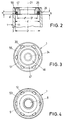
- ring seal 28 and possibly also the ring seal 10 in the undeformed state have an outer diameter d which is slightly smaller than the inner diameter D of the outer cylinder 3, the inner wall 11 of which is cylindrical throughout, that is to say over its entire length has a constant inner diameter D.
- the ring groove 26 in the ring 47 and the ring groove 10 receiving the ring groove 55 in the end ring 9 are formed so that when pressing the ring 47 against the contact surface 49 of the valve body 22 or when pressing the end ring 9 against the Cup-shaped sleeve 13, the ring seal 28 or the ring seal 10 are axially compressed in such a way that they are pressed radially outwards, as a result of which their outer diameter increases so much that the ring seal 28 or 10 lies sealingly against the inner wall 11 of the outer cylinder 3.
- the axial extent a of the annular groove 26 when the ring 47 is in contact with the contact surface 49 is therefore smaller than the thickness b of the ring seal 28 or 10 in the unstressed state, as can be seen from FIG. 2.
- the inside diameter d 'of the ring seal 28 or 10 corresponds to the inside diameter D' of the ring groove 26 or 55.
- the cross section e of the ring seal 28 is somewhat larger than the cross section of the ring groove 26. It therefore applies that e> 0.5 a (D - D ').
- the dimensional relationships outlined in FIG. 2 are only shown for the valve 19. So that the ring seal 10 does not lie outside of the ring groove 55 between the end ring 9 and the cup-shaped sleeve 13, the latter is provided with an annular collar 13a which is immersed in the ring groove 55 and causes the clamping of the ring seal 10 when compressed in the direction of the axis 21 .
- the gas spring is installed as follows: The entire valve 19 is pre-assembled and inserted into the associated end of the inner cylinder 2.
- the piston rod 8 with the piston 5 is inserted into the inner cylinder 2 from the other side.
- the centering piece 15 is inserted into the corresponding end of the inner cylinder 2.
- the cup-shaped sleeve 13 with the multiple lip seal 14 is pushed onto the free end of the piston rod 8, up to the stop on the centering piece 15.
- the end ring 9 with the ring seal 10 is loosely pushed onto the sleeve 13, specifically in the same way as the ring 47 with the ring seal 28 is attached to the nozzle-like area 48 of the valve body 22.
- This preassembled unit is inserted with the valve 19 into the outer cylinder 3.
- the inner wall 11 need not have a good surface quality, since the ring seal 28 or 10 does not adhere to it can be damaged. So it is not necessary that 3 seamless tubes are used for the outer cylinder, or that when using welded tubes they are retightened on the inside or in some other way a surface treatment be subjected.
- the outer surface 60 of the outer cylinder 3 must be brought to an exactly cylindrical shape with a low surface roughness, so that in the region of the valve 19 a cone 61 can also be screwed on, which od for attachment in a suitably designed receptacle on the underside of a chair seat. the like serves.
- the outer cylinder 3 of the gas spring is provided in its outer surface 60 with at least one indentation 62 directed inwards towards the axis 21, which corresponds to at least one projection 63 formed on the inner wall 11 of the outer cylinder.
- the indentation 62 and correspondingly the projection 63 can be formed by an annular surrounding bead.
- the cup-shaped sleeve 13 lies axially firmly against this at least one projection 63.
- the centering piece 15 ' is provided with an outer recess 64 which receives the at least one projection 63.
- the multiple lip seal 14 is supported - as in the embodiment according to FIG. 1 - in the direction of the axis 21 against the centering piece 15 '.
- nose-like projections 12a are provided which, like the projections 63, are produced by cup-shaped impressions 62a in the outer surface 60 of the outer cylinder 3 of the gas spring.
- the cup-shaped sleeve 13 is in turn supported against at least one projection 63.
- the multi-lip seal 14 is supported in the direction of the axis 21 and towards the housing space 17 against an annular disk 65, which in turn is supported against the centering piece 15 ′′, which has a recess partially receiving the at least one projection 63 64 ''.
- only one peripheral projection 12b is provided, which holds the end ring 9 and which - as already mentioned above Fig. 5 described - is generated by a peripheral bead 62b in the outer surface 60 of the outer cylinder 3.
- the centering piece 15 ′′ receives the at least one projection 63 in its recess 64 ′′ and is thereby fixed axially in the housing 1 in the direction of the end on the piston rod outlet side.
- the multiple lip seal 14 and the cup-shaped sleeve 13 are supported in the direction of the axis 21 and towards the housing space 17 against an annular disk 65 'which is supported against the at least one projection 63.
- it has an outer recess 66 which receives the at least one projection 63.
- the centering piece 15 ′′ is exposed relative to the annular disk 65 ′, which is indicated by a gap 67 in FIG. 7.
- the projection 12c is formed by a fastening element 11b arranged in an inner groove 11a in the inner wall 11 of the outer cylinder 3, for example a Seeger ring.
- FIG. 8 corresponds to that according to FIG. 5, the projection 12d resting against the end ring 9 being formed by a spacer sleeve 11c which is in a recess 11d in the inner wall 11 of the outer cylinder 3, in the region of the edge 57 thereof , is trained.
- the edge 57 is provided with a flange 57a which holds the spacer sleeve 11c and presses against the end ring 9.
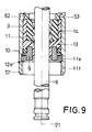
- FIG. 9 also essentially corresponds to that of FIG. 5, in which case the projection 12e is formed by a screw ring 11e which is screwed into an internal thread 11f on the inner wall 11, which is on the inner wall 11 of the outer cylinder 3 is formed in the region of the edge 57 thereof.
- cup-shaped sleeve 13 and the end ring 9 together form a sealing body 68.
- the cup-shaped sleeve 13 does not bear gas-tight against the inner wall 11 of the outer cylinder 3, the gap being so narrow that it cannot be represented in the drawing. With the measures described, this can be used to accomplish the filling of the gas spring with compressed gas.
- this can be used to accomplish the filling of the gas spring with compressed gas.
- this unit can be pressed together by means of a stamp on which the tools for producing the indentations 62 and thus the projections 63 are also attached. Subsequently, the cup-shaped sleeve 13, the seal 14 and the end ring 9 with the ring seal 10 are placed and the housing 1 is filled with compressed gas. If the housing 1 is filled with compressed gas, the projections 12 are produced in the manner described, the seal 10 being tensioned in the manner described, so that the housing 1 is then gas-tight. As the above description shows, the embodiments according to FIGS. 5 to 9 are particularly suitable for carrying out the gas filling in the manner described above.
- FIGS. 1, 5, 6, 7, 8, 9 it can be seen that the edge 57 of the outer tube 3 on the piston rod outlet end of the housing 1 protrudes beyond the end ring 9 and by a dimension f.
- FIG. 10 A chair column is shown there, which has a standpipe 69 in which a length-adjustable gas spring of the type described above is arranged as a pneumatic or hydropneumatic piston-cylinder adjusting element.
- the housing 1 of the gas spring is displaceably supported in the direction of the axis 21 in a guide bush 70 which is arranged in an end 71 of the standpipe 69, which is upper in FIG. 10.
- the outer cylinder 3 is supported in the guide bush 70.
- the piston rod 8 is supported by an axial roller bearing 72 against a base plate 73 of the standpipe 69 in the direction of the axis 21.
- the base plate 73 is located at the other end 74 of the standpipe 69 opposite the one end 71 - lower end in FIG. 10.
- a pin 75 of the piston rod 8 passing through the axial roller bearing 72 extends through an opening 76 which is concentric with the axis 21 Base plate 73. It is secured against being pulled out against the underside of base plate 73 by means of a spring securing clip 77.
- the diameter of the opening 76 is larger than the diameter of the pin 75.
- an annular disk-shaped damping element 79 for example made of rubber, is arranged, which serves as a stop damper when the housing 1 of the gas spring is put on, when the housing 1 of the gas spring is retracted as far as possible into the standpipe 69, i.e. the chair column has the lowest possible height.
- the edge 57 of the housing 1 overlaps the damping element 79 and, if appropriate, partially also the axial roller bearing 72 in the direction of the axis 21.
- the damping element 79 comes to rest on the end ring 9, namely on a stop collar 9a formed on it. This position is shown at the bottom right in FIG. 10. If, on the other hand, the piston rod 8 assumes its extended position as far as possible from the housing 1, in which the housing 1 is extended as far as possible from the standpipe 69, then the edge 57 also serves to guide the housing 1 in the guide bush 70, which is the exclusive lateral guide for the Housing 1 forms, since the piston rod 8 is arranged in the base plate 73 with radial play.
- a maximum of additional guide length of the housing 1 in the guide bushing 70 when the housing 1 is extended is achieved when the length f of the edge 57 is so great that the end face of the edge 57 just under extreme loading of the gas spring and thus with compressed damping element 79 does not touch the bottom plate 73.
- the diameters of the thrust roller bearing 71 and the damping element 79 must be selected so that the edge 57 of the outer cylinder 3, including the spacer sleeve 11c or the screw ring 11e, can be pushed over it without collision.
- the length f of the edge 57 can be> 5 mm and preferably 10 to 15 mm, which in turn significantly extends the guide length in the guide bushing 70, with the housing 1 extended as far as possible by 20 to 25%.
Landscapes
- Engineering & Computer Science (AREA)
- General Engineering & Computer Science (AREA)
- Mechanical Engineering (AREA)
- Fluid-Damping Devices (AREA)
Applications Claiming Priority (2)
| Application Number | Priority Date | Filing Date | Title |
|---|---|---|---|
| DE4420914 | 1994-06-16 | ||
| DE4420914A DE4420914A1 (de) | 1994-06-16 | 1994-06-16 | Längenverstellbare Gasfeder und längenverstellbare Säule für Stühle, Tische mit einer längenverstellbaren Gasfeder |
Publications (2)
| Publication Number | Publication Date |
|---|---|
| EP0687832A1 true EP0687832A1 (fr) | 1995-12-20 |
| EP0687832B1 EP0687832B1 (fr) | 1999-03-10 |
Family
ID=6520647
Family Applications (1)
| Application Number | Title | Priority Date | Filing Date |
|---|---|---|---|
| EP95106054A Expired - Lifetime EP0687832B1 (fr) | 1994-06-16 | 1995-04-22 | Ressort pneumatique réglable en longueur et colonne réglable en longueur pour chaises et tables ayant un ressort de longueur réglable |
Country Status (5)
| Country | Link |
|---|---|
| US (1) | US5570873A (fr) |
| EP (1) | EP0687832B1 (fr) |
| DE (2) | DE4420914A1 (fr) |
| ES (1) | ES2129695T3 (fr) |
| TW (1) | TW303639U (fr) |
Cited By (7)
| Publication number | Priority date | Publication date | Assignee | Title |
|---|---|---|---|---|
| FR2753892A1 (fr) * | 1996-10-02 | 1998-04-03 | Stabilus Gmbh | Fut de longueur reglable, notamment pour chaises ou tables |
| EP0802346A3 (fr) * | 1996-04-11 | 1998-12-23 | Gain Gas Technique, S.L. | Cylindre à gaz |
| WO1999027276A1 (fr) * | 1997-11-24 | 1999-06-03 | Cabex Ag | Support et son procede de fabrication |
| EP0804889A3 (fr) * | 1996-05-04 | 1999-12-29 | SUSPA COMPART Aktiengesellschaft | Ressort à gaz pour chaise |
| ITPN20090037A1 (it) * | 2009-06-09 | 2010-12-10 | Simone Bordignon | Cilindro a gas, particolarmente molla a gas, perfezionato |
| CN108991727A (zh) * | 2018-08-28 | 2018-12-14 | 乐歌人体工学科技股份有限公司 | 升降桌的升降装置 |
| US10253840B2 (en) * | 2014-12-25 | 2019-04-09 | Hitachi Automotive Systems, Ltd. | Cylinder apparatus |
Families Citing this family (13)
| Publication number | Priority date | Publication date | Assignee | Title |
|---|---|---|---|---|
| DE19604962A1 (de) * | 1996-02-10 | 1997-08-14 | Suspa Compart Ag | Längenverstellbare Gasfeder |
| DE19714646A1 (de) * | 1997-04-09 | 1998-10-15 | Suspa Compart Ag | Längenverstellbare Gasfeder |
| TW427142U (en) * | 1997-11-17 | 2001-03-21 | Samhongsa Co Ltd | Apparatus for adjusting the height of a swivel chair |
| PT1158201E (pt) * | 1999-11-04 | 2004-08-31 | Gain Gas Technique Sl | Dispositivo cilindrico de gas |
| DE10219583A1 (de) * | 2001-06-01 | 2002-12-05 | Stabilus Gmbh | Objektträgersäule |
| DK200101808A (da) * | 2001-12-05 | 2003-06-06 | Linak As | En løftesøjle, fortrinsvis til højdejusterbare borde samt fremgangsmåde til fremstilling heraf |
| ES2199074B1 (es) * | 2002-07-19 | 2005-05-01 | Gain Gas Technique, S.L. | Cilindro a gas no autoportante. |
| ES2208090B1 (es) * | 2002-07-23 | 2005-10-16 | Gain Gas Technique, S.L. | Cilidro a gas no autoportante. |
| KR100519624B1 (ko) * | 2003-03-03 | 2005-10-11 | (주)삼협 | 길이조절 가스스프링 |
| DE102005019053B4 (de) * | 2005-04-23 | 2010-12-02 | Stabilus Gmbh | Gasfederanordnung |
| JP2009002382A (ja) * | 2007-06-19 | 2009-01-08 | Aisan Ind Co Ltd | 流体制御バルブ装置 |
| TW200907199A (en) * | 2007-08-03 | 2009-02-16 | Taiwan Fluid Control & Amp Applic Company Co Ltd | Shock absorber |
| CN207005175U (zh) * | 2017-06-08 | 2018-02-13 | 常州市莱特气弹簧有限公司 | 压力可调气弹簧 |
Citations (4)
| Publication number | Priority date | Publication date | Assignee | Title |
|---|---|---|---|---|
| DE1812282A1 (de) * | 1968-12-03 | 1970-06-18 | Suspa Federungstech | Hubvorrichtung zum stufenlosen Hoeherverstellen von Tischplatten,Stuhlsitzen u.dgl. |
| US4096785A (en) * | 1975-06-28 | 1978-06-27 | Stabilus Gmbh | Elastic column of adjustable length |
| DE1924254B2 (de) * | 1969-05-12 | 1978-07-20 | Ignaz Vogel Gmbh Und Co Kg - Fahrzeugsitze, 7500 Karlsruhe | Hydraulische Feststelleinrichtung |
| FR2586771A1 (fr) * | 1985-08-28 | 1987-03-06 | Socalfram | Ressort pneumatique blocable |
Family Cites Families (7)
| Publication number | Priority date | Publication date | Assignee | Title |
|---|---|---|---|---|
| DE8630918U1 (de) * | 1986-11-18 | 1987-11-05 | Fritz Bauer + Söhne oHG, 8503 Altdorf | Längenverstellbare Gasfeder für höhenverstellbare Stühle, Tische od.dgl. |
| DE3833959A1 (de) * | 1988-10-06 | 1990-04-12 | Bauer Fritz & Soehne Ohg | Laengenverstellbare saeule fuer stuehle, tische oder dergleichen |
| DE4009035A1 (de) * | 1990-03-21 | 1991-09-26 | Suspa Federungstech | Laengenverstellbare gasfeder |
| DE4009034A1 (de) * | 1990-03-21 | 1991-09-26 | Suspa Federungstech | Laengenverstellbare gasfeder |
| DE4114226A1 (de) * | 1991-05-01 | 1992-11-05 | Suspa Compart Ag | Laengenverstellbare gasfeder |
| DE4233407A1 (de) * | 1992-10-05 | 1994-04-07 | Stabilus Gmbh | Führung für teleskopartig ineinander verschiebbare zylindrische Teile |
| DE9402656U1 (de) * | 1994-02-18 | 1994-04-14 | Suspa Compart Ag, 90518 Altdorf | Führungsbüchse und längenverstellbare Säule mit Führungsbüchse |
-
1994
- 1994-06-16 DE DE4420914A patent/DE4420914A1/de not_active Withdrawn
- 1994-08-10 TW TW083211539U patent/TW303639U/zh unknown
-
1995
- 1995-04-22 ES ES95106054T patent/ES2129695T3/es not_active Expired - Lifetime
- 1995-04-22 DE DE59505248T patent/DE59505248D1/de not_active Expired - Lifetime
- 1995-04-22 EP EP95106054A patent/EP0687832B1/fr not_active Expired - Lifetime
- 1995-06-14 US US08/490,527 patent/US5570873A/en not_active Expired - Lifetime
Patent Citations (4)
| Publication number | Priority date | Publication date | Assignee | Title |
|---|---|---|---|---|
| DE1812282A1 (de) * | 1968-12-03 | 1970-06-18 | Suspa Federungstech | Hubvorrichtung zum stufenlosen Hoeherverstellen von Tischplatten,Stuhlsitzen u.dgl. |
| DE1924254B2 (de) * | 1969-05-12 | 1978-07-20 | Ignaz Vogel Gmbh Und Co Kg - Fahrzeugsitze, 7500 Karlsruhe | Hydraulische Feststelleinrichtung |
| US4096785A (en) * | 1975-06-28 | 1978-06-27 | Stabilus Gmbh | Elastic column of adjustable length |
| FR2586771A1 (fr) * | 1985-08-28 | 1987-03-06 | Socalfram | Ressort pneumatique blocable |
Cited By (11)
| Publication number | Priority date | Publication date | Assignee | Title |
|---|---|---|---|---|
| EP0802346A3 (fr) * | 1996-04-11 | 1998-12-23 | Gain Gas Technique, S.L. | Cylindre à gaz |
| EP0804889A3 (fr) * | 1996-05-04 | 1999-12-29 | SUSPA COMPART Aktiengesellschaft | Ressort à gaz pour chaise |
| FR2753892A1 (fr) * | 1996-10-02 | 1998-04-03 | Stabilus Gmbh | Fut de longueur reglable, notamment pour chaises ou tables |
| ES2147496A1 (es) * | 1996-10-02 | 2000-09-01 | Stabilus Gmbh | Columna de longitud regulable. |
| WO1999027276A1 (fr) * | 1997-11-24 | 1999-06-03 | Cabex Ag | Support et son procede de fabrication |
| US6336624B1 (en) | 1997-11-24 | 2002-01-08 | Cabex Ag | Adjustable length column/support |
| ITPN20090037A1 (it) * | 2009-06-09 | 2010-12-10 | Simone Bordignon | Cilindro a gas, particolarmente molla a gas, perfezionato |
| EP2261526A1 (fr) * | 2009-06-09 | 2010-12-15 | Bordignon Simone S.r.l. | Cylindre à gaz, en particulier ressort à gaz |
| US10253840B2 (en) * | 2014-12-25 | 2019-04-09 | Hitachi Automotive Systems, Ltd. | Cylinder apparatus |
| CN108991727A (zh) * | 2018-08-28 | 2018-12-14 | 乐歌人体工学科技股份有限公司 | 升降桌的升降装置 |
| CN108991727B (zh) * | 2018-08-28 | 2023-11-28 | 乐歌人体工学科技股份有限公司 | 升降桌的升降装置 |
Also Published As
| Publication number | Publication date |
|---|---|
| TW303639U (en) | 1997-04-21 |
| ES2129695T3 (es) | 1999-06-16 |
| DE59505248D1 (de) | 1999-04-15 |
| US5570873A (en) | 1996-11-05 |
| DE4420914A1 (de) | 1995-12-21 |
| EP0687832B1 (fr) | 1999-03-10 |
Similar Documents
| Publication | Publication Date | Title |
|---|---|---|
| EP0687832B1 (fr) | Ressort pneumatique réglable en longueur et colonne réglable en longueur pour chaises et tables ayant un ressort de longueur réglable | |
| DE2942455C2 (fr) | ||
| EP0353549B1 (fr) | Dispositif de positionnement à longueur réglable | |
| DE2813992C3 (de) | Hydraulischer Stoßdämpfer des Doppelrohrtyps | |
| DE2922437C2 (fr) | ||
| DE2715826C2 (de) | Hydraulischer Stoßdämpfer des Doppelrohrtyps | |
| DE10122796B4 (de) | Kolben-Zylinderaggregat mit einem Faltbalg | |
| DE2312445A1 (de) | Unter druck stehender stossdaempfer.101509 | |
| DE2225342B2 (de) | Laengenverstellbare gasfeder | |
| DE2553246A1 (de) | Stossdaempfer | |
| DE2600408A1 (de) | Fahrzeugaufhaengungsvorrichtung | |
| DE3151050C2 (fr) | ||
| DE4226180A1 (de) | Kolben-Kolbenstangen-Einheit und Verfahren zu deren Herstellung | |
| EP0217013A1 (fr) | Ressort à gaz réglable en longueur | |
| DE7708863U1 (de) | Dichtung für die Kolbenstange eines Stoßdämpfers | |
| EP0343335B1 (fr) | Ressort pneumatique | |
| DE2948391A1 (de) | Kolben-zylinder-aggregat mit einem im wesentlichen rohrfoermigen behaelter | |
| DE3150231A1 (de) | Verschlussdeckel, insbesondere fuer einen kuehlerstutzen eines kraftfahrzeugs | |
| DE1186694B (de) | Hydraulisch-mechanischer Stossdaempfer | |
| DE2907100A1 (de) | Laengenverstellbare gasfeder | |
| DE19631608C1 (de) | Schwingungsdämpfer mit veränderbarer Dämpfkraft | |
| DE2408055A1 (de) | Laengenverstellbares, druckmittelbeaufschlagtes, hydraulisch blockierbares verstellaggregat | |
| EP1441146B1 (fr) | Amortisseur de vibrations | |
| DE3141664C2 (fr) | ||
| DE2310237A1 (de) | Hydropneumatischer stossfaenger, vorzugsweise fuer stosstangen von kraftfahrzeugen |
Legal Events
| Date | Code | Title | Description |
|---|---|---|---|
| PUAI | Public reference made under article 153(3) epc to a published international application that has entered the european phase |
Free format text: ORIGINAL CODE: 0009012 |
|
| AK | Designated contracting states |
Kind code of ref document: A1 Designated state(s): DE ES FR IT |
|
| 17P | Request for examination filed |
Effective date: 19960418 |
|
| GRAG | Despatch of communication of intention to grant |
Free format text: ORIGINAL CODE: EPIDOS AGRA |
|
| GRAG | Despatch of communication of intention to grant |
Free format text: ORIGINAL CODE: EPIDOS AGRA |
|
| GRAH | Despatch of communication of intention to grant a patent |
Free format text: ORIGINAL CODE: EPIDOS IGRA |
|
| GRAH | Despatch of communication of intention to grant a patent |
Free format text: ORIGINAL CODE: EPIDOS IGRA |
|
| 17Q | First examination report despatched |
Effective date: 19980825 |
|
| GRAA | (expected) grant |
Free format text: ORIGINAL CODE: 0009210 |
|
| AK | Designated contracting states |
Kind code of ref document: B1 Designated state(s): DE ES FR IT |
|
| ET | Fr: translation filed | ||
| REF | Corresponds to: |
Ref document number: 59505248 Country of ref document: DE Date of ref document: 19990415 |
|
| ITF | It: translation for a ep patent filed | ||
| REG | Reference to a national code |
Ref country code: ES Ref legal event code: FG2A Ref document number: 2129695 Country of ref document: ES Kind code of ref document: T3 |
|
| PLBE | No opposition filed within time limit |
Free format text: ORIGINAL CODE: 0009261 |
|
| STAA | Information on the status of an ep patent application or granted ep patent |
Free format text: STATUS: NO OPPOSITION FILED WITHIN TIME LIMIT |
|
| 26N | No opposition filed | ||
| PGFP | Annual fee paid to national office [announced via postgrant information from national office to epo] |
Ref country code: ES Payment date: 20080424 Year of fee payment: 14 |
|
| PGFP | Annual fee paid to national office [announced via postgrant information from national office to epo] |
Ref country code: FR Payment date: 20080418 Year of fee payment: 14 |
|
| REG | Reference to a national code |
Ref country code: FR Ref legal event code: ST Effective date: 20091231 |
|
| PG25 | Lapsed in a contracting state [announced via postgrant information from national office to epo] |
Ref country code: FR Free format text: LAPSE BECAUSE OF NON-PAYMENT OF DUE FEES Effective date: 20091222 |
|
| REG | Reference to a national code |
Ref country code: ES Ref legal event code: FD2A Effective date: 20090423 |
|
| PG25 | Lapsed in a contracting state [announced via postgrant information from national office to epo] |
Ref country code: ES Free format text: LAPSE BECAUSE OF NON-PAYMENT OF DUE FEES Effective date: 20090423 |
|
| PGFP | Annual fee paid to national office [announced via postgrant information from national office to epo] |
Ref country code: IT Payment date: 20110422 Year of fee payment: 17 |
|
| PG25 | Lapsed in a contracting state [announced via postgrant information from national office to epo] |
Ref country code: IT Free format text: LAPSE BECAUSE OF NON-PAYMENT OF DUE FEES Effective date: 20120422 |
|
| PGFP | Annual fee paid to national office [announced via postgrant information from national office to epo] |
Ref country code: DE Payment date: 20140430 Year of fee payment: 20 |
|
| REG | Reference to a national code |
Ref country code: DE Ref legal event code: R071 Ref document number: 59505248 Country of ref document: DE |