EP0687882A1 - Mécanisme de mise à poste d'une munition - Google Patents
Mécanisme de mise à poste d'une munition Download PDFInfo
- Publication number
- EP0687882A1 EP0687882A1 EP95401376A EP95401376A EP0687882A1 EP 0687882 A1 EP0687882 A1 EP 0687882A1 EP 95401376 A EP95401376 A EP 95401376A EP 95401376 A EP95401376 A EP 95401376A EP 0687882 A1 EP0687882 A1 EP 0687882A1
- Authority
- EP
- European Patent Office
- Prior art keywords
- rotation
- stop
- ammunition
- mechanism according
- lever
- Prior art date
- Legal status (The legal status is an assumption and is not a legal conclusion. Google has not performed a legal analysis and makes no representation as to the accuracy of the status listed.)
- Granted
Links
- 230000000694 effects Effects 0.000 claims description 7
- 230000002093 peripheral effect Effects 0.000 claims description 2
- 238000012163 sequencing technique Methods 0.000 claims description 2
- 238000013016 damping Methods 0.000 description 2
- 238000000605 extraction Methods 0.000 description 2
- 230000000295 complement effect Effects 0.000 description 1
- 238000010304 firing Methods 0.000 description 1
- 230000037431 insertion Effects 0.000 description 1
- 238000003780 insertion Methods 0.000 description 1
Images


Classifications
-
- F—MECHANICAL ENGINEERING; LIGHTING; HEATING; WEAPONS; BLASTING
- F41—WEAPONS
- F41A—FUNCTIONAL FEATURES OR DETAILS COMMON TO BOTH SMALLARMS AND ORDNANCE, e.g. CANNONS; MOUNTINGS FOR SMALLARMS OR ORDNANCE
- F41A9/00—Feeding or loading of ammunition; Magazines; Guiding means for the extracting of cartridges
- F41A9/01—Feeding of unbelted ammunition
- F41A9/06—Feeding of unbelted ammunition using cyclically moving conveyors, i.e. conveyors having ammunition pusher or carrier elements which are emptied or disengaged from the ammunition during the return stroke
- F41A9/09—Movable ammunition carriers or loading trays, e.g. for feeding from magazines
- F41A9/10—Movable ammunition carriers or loading trays, e.g. for feeding from magazines pivoting or swinging
- F41A9/13—Movable ammunition carriers or loading trays, e.g. for feeding from magazines pivoting or swinging in a vertical plane
- F41A9/14—Movable ammunition carriers or loading trays, e.g. for feeding from magazines pivoting or swinging in a vertical plane which is transverse to the barrel axis
-
- F—MECHANICAL ENGINEERING; LIGHTING; HEATING; WEAPONS; BLASTING
- F41—WEAPONS
- F41A—FUNCTIONAL FEATURES OR DETAILS COMMON TO BOTH SMALLARMS AND ORDNANCE, e.g. CANNONS; MOUNTINGS FOR SMALLARMS OR ORDNANCE
- F41A9/00—Feeding or loading of ammunition; Magazines; Guiding means for the extracting of cartridges
- F41A9/38—Loading arrangements, i.e. for bringing the ammunition into the firing position
- F41A9/39—Ramming arrangements
- F41A9/42—Rammers separate from breech-block
Definitions
- the subject of the present invention is a mechanism for placing ammunition in the breech chamber of a medium or large caliber weapon, comprising on the one hand a device for feeding the ammunition which is rotated by a drive device and on the other hand at least one delivery means and a means for jamming the ammunition operating successively, the delivery means and the jamming means being integral in rotation with the feed device, the latter performing during a cycle of placing the munition successively a first rotation positioning the ammunition on the one hand in the axis of the breech chamber and on the other hand the delivery means to allow it to carry out a delivery of the ammunition, and a second rotation positioning the wedging means to allow it to wedge the ammunition in the forcing cone.
- the first and second rotations take place around two different axes, that is to say with a complex movement, hence a mechanical complexity which has as a corollary a relative mechanical fragility of the whole , not very compatible with the requirements of the new types of artillery equipment.
- the subject of the present invention is a post-setting mechanism of the aforementioned type, but which has a mechanism which is both simpler and more robust than in the prior art.
- the basic idea of the invention is to carry out the two rotations around a single axis so as to obtain the desired simplicity, and consequently, also to save on the time of a complete loading cycle.
- the shift mechanism according to the invention is characterized in that it comprises a rotary part allowing the first and second rotations of the feeding device to take place around the same axis of rotation cooperating with a means of retractable stop allowing the rotation of the feed device to be stopped in a position corresponding to the end of the first rotation.
- the retractable stop means may comprise a retracting device moving the stop means between two positions, namely a first, active position, in which the stop means is capable of causing the rotation of the device to stop. end feed first rotation, and a second position, inactive, in which the stop means is cleared and does not act on the rotation of the feed device.
- the retractable abutment means advantageously comprises a first abutment lever sliding longitudinally relative to said rotary part, but integral in rotation with said part, the feed device comprising means for sliding the first abutment lever along said part rotatable between said first and second positions.
- the first stop lever may in particular comprise a peripheral groove, the means for moving the first lever then comprising a fork engaging in said groove.
- the retractable stop means comprises a second stop lever cooperating with a stop at the end of the first rotation, the first stop lever being capable of driving the second stop lever only when it is in his first position.
- the fork can be articulated around an axis of articulation.
- the fork may have first and second branches, each of which has a region such as a finger engaging in said groove.
- the first branch may include, at one end, a control finger constituting said means for sliding the first stop lever.
- the post-setting mechanism may include a rigid box supporting the drive device, the retractable stop means and said rotary part.
- the mechanism may include means for controlling, between steps a and c , an outward movement of the delivery means so as to effect said delivery of the ammunition and for controlling, between steps c and d , an outward movement of the jamming means so as to effect said jamming of the ammunition, then a return movement of the jamming means.
- the mechanism comprises means for controlling, during step d , a return movement of the delivery means.
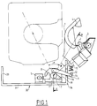
- a device for supplying ammunition 50 comprises a stretcher 1 of semi-circular shape whose concavity is directed upwards and which is provided with an anti-extraction device 4, known per se, which is intended to prevent the ejection of the shell 50 during the rotation of the stretcher 1.
- the stretcher 1 is movable in rotation about a single axis, which is the axis of rotation of a part cylindrical 11.
- a support comprising on the one hand a perforated plate 22 at 26 which extends radially from the cylindrical part 11 to the stretcher 1 and on the other hand two support elements lateral 24 and 25 orthogonal to the plate 22 and the ends 24 'and 25' of which enclose the stretcher 1 so as to constitute a rigid mechanical assembly.
- the stretcher 1 is rotated by a rotary actuator 6 with a helical piston.
- a chain repressor 2 driven by a hydraulic motor and a linear wedging cylinder 3 are mounted on the stretcher 1 and are integral with its rotation about the axis of the part 11.
- the whole is powered by an electro-hydraulic block, itself controlled by an electric control console.
- a lever 7 carrying a drive finger 18 is integral in rotation with the part 11, but its position along the latter is controlled by a fork 8 actuated by a stop cylinder 5.
- This drive in rotation of the lever 7, independently of its longitudinal position along the part 11, is obtained by complementary grooves 15 of an extension 11 'of the part 11, and of the lever 7, which are shown in FIGS. 8 and 9.
- the finger 18 of the lever 7 makes it possible to drive a second lever 9 in rotation as far as a damping stop 10. At its end 14 there is a stop finger 12.
- the fork 8, controlled by the stop cylinder 5, makes it possible to move the lever 7 longitudinally along the axis 11 between an active position in which the pin 18 is capable of rotating the lever 9 and an inactive position in which the rotation of the lever 7 cannot have any influence on the lever 9.
- the lever 9 is recalled by its own weight or by a spring (not shown) in a low position where it is released from the stop 10 and comes to rest in its bottom dead center on a lower edge 16 of an opening of one of the edges 34 of a support box 30 rigid U-shaped having a bottom plate 31 and a second flange 33.
- the box 30 stiffens the assembly and carries a U-shaped plate 36, the branches 37 and 38 of which support the rotary actuator 6, the mechanism retractable stop 5, 7, 8, 9 and one end of the part 11, the other end of which is held by a wing 39 forming an extension of the bottom plate 31, which adjoins the rim 34.
- the shift mechanism then operates according to the following cycle:
- a shell 50 is deposited in the stretcher 1, which is in the insertion position shown in FIGS. 1 and 2. In this position, the chain repressor 2 is at rest. The linear wedging cylinder 3 is retracted rod, the stop cylinder 5 is retracted rod (see Figure 7), which corresponds to the active position of the lever 7, and the rotary cylinder 6 is at rest. The anti-extraction device 4 prevents the shell from being ejected during the first rotation movement of the stretcher 1.
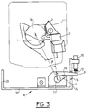
- a first angle rotation ⁇ of the stretcher 1 is carried out around the axis of the part 11 from the position shown in FIG. 1 to the position shown in FIG. 3, in which the arm 9, driven by the finger 18, is applied by its abutment finger 12 against the damping abutment 10.
- the shell 50 has its axis aligned with that of the breech chamber 40 of the barrel and the chain repressor 2 is in a position in which it can repress the shell 50 from the stretcher 1 to the breech chamber 40.
- This repression step is initiated by a position detector of the stretcher 1 which controls the advance of the chain repressor 2.
- a second position detector controls the output of the rod of the stop cylinder 5, which has the effect of releasing the finger 18 from its action on the lever 9, which returns to its bottom dead center, and release the grooved lever 7 to allow it to p continue its rotation without exerting any action on the lever 9.
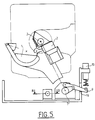
- the stretcher 1 then performs a second angle rotation ⁇ , still under the action of the rotary actuator 6 left under pressure from the position shown in Figure 3 to the position shown in Figure 5.
- the cylinder wedge 3 is brought into alignment with the cylinder head chamber 40 of the muzzle.
- a position detector of the stretcher 1 controls the output of the rod 23 of the wedging cylinder 3 and locks in the firing position the shell 50 in the forcing cone 60 of the chamber 40.
- An electro-hydraulic device hydraulically connected to the rod 23 of the jack 3 controls, as soon as the oil flow drops, the reentry of the rod 23.
- a reentry detector of the rod 23 then controls the return of the stretcher 1 in starting position (FIG. 1) as well as the return of the repressor 2.
- a last detector in the starting position controls the retraction of the stop cylinder 5, which again positions the lever 7 in the active position. The loading device is then ready for a new cycle.
- the device which has been described above, saves time, on the one hand due to the fact that the return of the repressor 2 can be done entirely in masked time and, on the other hand that the return time of rotation of the arm is faster than in the prior art thanks to the unique movement, which contributes to reducing the time of a complete cycle and consequently improves the rate of fire of the material.
- FIG. 7 shows the lever 7 in its active position where the pin 18 rotates the lever 9. This position corresponds to the rod 82 position retracted from the stop cylinder 5.
- the fork 8 has the general shape of an inverted U ( see Figure 9) which has an upper central branch 84 and two lateral branches 83 and 85 which extend downwards. At its upper part 88, which surmounts the central branch 84, is disposed a hinge 89 allowing the fork 8 to be movable in rotation about a horizontal axis perpendicular to the axis of rotation of the part 11.
- the lower part of the branch 83 has an extension 82 which ends with a finger 81 which engages in the rod 82, which makes it possible to control the movement of the fork 8.
- the middle part of the branches 83 and 85 carries extensions 83 and 87 engaging in a groove 71 of a cylindrical part 72 extending the lever 7 along the axis of the part 11.
- the fork 8 can thus be moved between the active position of the lever 7 (in solid lines in FIG. 10) in which the finger 18 can rotate the lever 9 and a second position making an angle with the vertical and in which, the jack 5 being in the rod 82 out position, the finger 18 is moved (to the right in FIG. 10) so as to be separated from the lever 9 (see the dotted lines in Figure 10).
- FIG. 8 also shows the various positions of the levers 7 and 9 and more particularly the three characteristic positions of the lever 7, namely the first starting position shown in solid lines, then, after the first rotation, the first position corresponding to the setting in stop of the lever 9 (also shown in dotted lines) then finally, the rotation pushing against the clockwise direction, the third position after second rotation in which a rear extension 19 of the lever 7 abuts on a stop 13 indicating the end of the second rotation.
Landscapes
- Engineering & Computer Science (AREA)
- General Engineering & Computer Science (AREA)
- Portable Nailing Machines And Staplers (AREA)
- Transmission Devices (AREA)
Abstract
Description
- La présente invention a pour objet un mécanisme de mise à poste d'une munition dans la chambre de culasse d'une arme de moyen ou de gros calibre, comportant d'une part un dispositif d'amenage de la munition qui est entraîné en rotation par un dispositif d'entraînement et d'autre part au moins un moyen de refoulement et un moyen de coincement de la munition opérant successivement, le moyen de refoulement et le moyen de coincement étant solidaires en rotation du dispositif d'amenage, ce dernier effectuant au cours d'un cycle de mise à poste de la munition successivement une première rotation positionnant d'une part la munition dans l'axe de la chambre de culasse et d'autre part le moyen de refoulement pour lui permettre d'effectuer un refoulement de la munition, et une deuxième rotation positionnant le moyen de coincement pour lui permettre d'effectuer le coincement de la munition dans le cône de forcement.
- Un tel mécanisme de mise à poste est connu de la Demande de Brevet français 2 448 121, déposée par l'Etat Français, le 5 février 1979.
- Dans celui-ci, la première et la deuxième rotations s'effectuent autour de deux axes différents, c'est-à-dire avec un mouvement complexe, d'où une complexité mécanique qui a pour corollaire une relative fragilité mécanique de l'ensemble, peu compatible avec les exigences des nouveaux types de matériels d'artillerie.
- La présente invention a pour objet un mécanisme de mise à poste du type précité, mais qui présente un mécanisme à la fois plus simple et plus robuste que dans l'Art Antérieur.
- L'idée de base de l'invention est d'effectuer les deux rotations autour d'un axe unique de manière à obtenir la simplicité souhaitée, et en conséquence, de gagner également sur le temps d'un cycle complet de chargement.
- Le mécanisme de mise à poste selon l'invention est caractérisé en ce qu'il comporte une pièce rotative permettant que la première et la deuxième rotations du dispositif d'amenage s'effectuent autour d'un même axe de rotation coopérant avec un moyen de butée escamotable permettant d'arrêter la rotation du dispositif d'amenage dans une position correspondant à la fin de la première rotation.
- Le moyen de butée escamotable peut comporter un dispositif d'escamotage déplaçant le moyen de butée entre deux positions, à savoir une première position, active, dans laquelle le moyen de butée est à même de provoquer l'arrêt de la rotation du dispositif d'amenage en fin de première rotation, et une deuxième position, inactive, dans laquelle le moyen de butée est effacé et n'agit pas sur la rotation du dispositif d'amenage.
- Le moyen de butée escamotable comporte avantageusement un premier levier de butée coulissant longitudinalement par rapport à ladite pièce rotative, mais solidaire en rotation de ladite pièce, le dispositif d'amenage comportant un moyen pour faire coulisser le premier levier de butée le long de ladite pièce rotative entre lesdites première et deuxième positions. Le premier levier de butée peut en particulier comporter une rainure périphérique, le moyen pour déplacer le premier levier comportant alors une fourchette s'engageant dans ladite rainure.
- Selon un mode de réalisation préféré, le moyen de butée escamotable comporte un deuxième levier de butée coopérant avec une butée de fin de première rotation, le premier levier de butée étant susceptible d'entraîner le deuxième levier de butée seulement lorsqu'il se trouve dans sa première position.
- La fourchette peut être articulée autour d'un axe d'articulation.
- La fourchette peut comporter une première et une deuxième branches dont chacune présente une région telle qu'un doigt s'engageant dans ladite rainure. La première branche peut comporter, à une extrémité, un doigt de commande constituant ledit moyen pour faire coulisser le premier levier de butée.
- Le mécanisme de mise à poste peut comporter un caisson rigide supportant le dispositif d'entraînement, le moyen de butée escamotable et ladite pièce rotative.
- Le mécanisme de mise à poste comporte avantageusement un dispositif de commande assurant le séquencement suivant de la rotation du dispositif d'amenage :
- a) déplacer le dispositif d'entraînement pour effectuer la première rotation, le moyen de butée escamotable étant dans sa première position ;
- b) placer le moyen de butée escamotable dans sa deuxième position ;
- c) déplacer le dispositif d'entraînement pour effectuer la deuxième rotation ;
- d) déplacer le dispositif d'entraînement pour effectuer le retour des deuxième et première rotations ;
- e) placer le moyen de butée escamotable dans sa première position.
- Le mécanisme peut comporter un moyen pour commander, entre les étapes a et c, un déplacement aller du moyen de refoulement de manière à effectuer ledit refoulement de la munition et pour commander, entre les étapes c et d, un déplacement aller du moyen de coincement de manière à effectuer ledit coincement de la munition, puis un déplacement retour du moyen de coincement.
- Selon un mode de réalisation préféré, le mécanisme comporte un moyen pour commander, au cours de l'étape d, un déplacement retour du moyen de refoulement.
- L'invention sera mieux comprise à la lecture de la description qui va suivre, en liaison avec les dessins ci-annexés, qui représentent un mode de réalisation préféré de l'invention et dans lesquels :
- les figures 1 et 2 représentent, respectivement en vue avant et en vue latérale droite (coupe partielle AA de la figure 1), un dispositif selon l'invention, en position d'introduction d'une munition ;
- la figure 3 représente le dispositif de la figure 1 après une première rotation du dispositif d'amenage ;
- la figure 4 représente, en vue de dessus, l'introduction d'une munition dans la chambre de culasse d'un canon ;
- la figure 5 représente le dispositif de la figure 3, après deuxième rotation du dispositif d'amenage pour mise en position du vérin de coincement ;
- la figure 6 représente, en vue de dessus, la fin de l'introduction et le coincement de la munition dans le cône de forcement d'un tube de bouche à feu ;
- la figure 7 représente, en vue de dessus avec coupe partielle BB de la figure 5, un mode de réalisation préféré du dispositif d'escamotage de la butée ;
- la figure 8 est une coupe transversale CC de la figure 7, illustrant deux positions caractéristiques du moyen de butée escamotable selon l'invention ;
- la figure 9 est une coupe transversale DD de la figure 7 ;
- la figure 10 est une vue latérale de la figure 9 illustrant deux positions caractéristiques du déplacement de la fourchette selon un mode de réalisation préféré de l'invention ;
- la figure 11 est une vue en perspective d'un dispositif selon l'invention, avec enlèvement du dispositif d'escamotage de la butée escamotable.
- Comme le montrent les figures 1 et 2, un dispositif d'amenage d'une munition 50 comporte une civière 1 de forme semi-circulaire dont la concavité est dirigée vers le haut et qui est pourvue d'un dispositif anti-extraction 4, connu en soi, qui est destiné à empêcher l'éjection de l'obus 50 lors de la rotation de la civière 1. La civière 1 est mobile en rotation autour d'un seul axe, qui est l'axe de rotation d'une pièce cylindrique 11. Elle est raccordée mécaniquement à la pièce 11 par un support comportant d'une part une plaque 22 ajourée en 26 qui s'étend radialement depuis la pièce cylindrique 11 jusqu'à la civière 1 et d'autre part deux éléments de support latéraux 24 et 25 orthogonaux à la plaque 22 et dont les extrémités 24' et 25' viennent enserrer la civière 1 de manière à constituer un ensemble mécanique rigide.
- La civière 1 est entraînée en rotation par un vérin rotatif 6 à piston hélicoïdal.
- Un refouloir à chaîne 2 mû par un moteur hydraulique et un vérin linéaire de coincement 3 sont montés sur la civière 1 et sont solidaires de sa rotation autour de l'axe de la pièce 11.
- L'ensemble est alimenté par un bloc électro-hydraulique, lui-même piloté par un pupitre de commande électrique.
- Un levier 7 portant un doigt d'entraînement 18 est solidaire en rotation de la pièce 11, mais sa position le long de celui-ci est commandée par une fourchette 8 actionnée par un vérin de butée 5. Cet entraînement en rotation du levier 7, indépendamment de sa position longitudinale le long de la pièce 11, est obtenu par des cannelures complémentaires 15 d'un prolongement 11' de la pièce 11, et du levier 7, qui sont représentées aux figures 8 et 9.
- Le doigt 18 du levier 7 permet d'entraîner en rotation jusqu'à une butée amortisseur 10 un deuxième levier 9 portant à son extrémité 14 un doigt de butée 12.
- La fourchette 8, commandée par le vérin de butée 5, permet de déplacer le levier 7 longitudinalement le long de l'axe 11 entre une position active dans laquelle le pion 18 est susceptible d'entraîner en rotation le levier 9 et une position inactive dans laquelle la rotation du levier 7 ne peut avoir aucune influence sur le levier 9. On remarquera par ailleurs que le levier 9 est rappelé par son propre poids ou bien par un ressort (non représenté) dans une position basse où il est dégagé de la butée 10 et vient reposer en son point mort bas sur un bord inférieur 16 d'une ouverture d'un des bords 34 d'un caisson support 30 rigide en forme de U présentant une plaque de fond 31 et un deuxième rebord 33. Le caisson 30 rigidifie l'ensemble et porte une platine 36 en forme de U, dont les branches 37 et 38 supportent le vérin rotatif 6, le mécanisme de butée escamotable 5, 7, 8, 9 et une extrémité de la pièce 11 dont l'autre extrémité est maintenue par une aile 39 formant un prolongement de la plaque de fond 31, qui jouxte le rebord 34.
- Le fonctionnement du mécanisme de mise à poste s'effectue alors selon le cycle suivant :
- Un obus 50 est déposé dans la civière 1, qui se trouve dans la position d'introduction représentée aux figures 1 et 2. Dans cette position, le refouloir à chaîne 2 est au repos. Le vérin linéaire de coincement 3 est tige rentrée, le vérin de butée 5 est tige rentrée (voir figure 7), ce qui correspond à la position active du levier 7, et le vérin rotatif 6 est au repos. Le dispositif anti-extraction 4 empêche l'éjection de l'obus lors du premier mouvement de rotation de la civière 1.
- Une première rotation d'angle α de la civière 1 est effectuée autour de l'axe de la pièce 11 depuis la position représentée à la figure 1 jusqu'à la position représentée à la figure 3, dans laquelle le bras 9, entraîné par le doigt 18, vient s'appliquer par son doigt de butée 12 contre la butée amortisseur 10. Dans cette position, l'obus 50 voit son axe aligné avec celui de la chambre de culasse 40 du canon et le refouloir à chaîne 2 est dans une position dans laquelle il peut effectuer un refoulement de l'obus 50 depuis la civière 1 jusqu'à la chambre de culasse 40. Cette étape de refoulement est initiée par un détecteur de position de la civière 1 qui commande l'avance du refouloir à chaîne 2. En outre, un deuxième détecteur de position commande la sortie de la tige du vérin de butée 5, ce qui a pour effet de dégager le doigt 18 de son action sur le levier 9, qui retombe à son point mort bas, et de libèrer le levier cannelé 7 pour lui permettre de poursuivre sa rotation sans exercer d'action sur le levier 9.
- La civière 1 effectue alors une deuxième rotation d'angle β, toujours sous l'action du vérin rotatif 6 laissé sous pression depuis la position représentée à la figure 3 jusqu'à la position représentée à la figure 5. Dans cette deuxième position (voir figure 5), le vérin de coincement 3 est mis en alignement avec la chambre de culasse 40 de la bouche à feu. Un détecteur de position de la civière 1 commande la sortie de la tige 23 du vérin de coincement 3 et bloque en position de tir l'obus 50 dans le cône de forcement 60 de la chambre 40.
- Un dispositif electro-hydraulique relié hydrauliquement à la tige 23 du vérin 3 commande, dès la chute de débit de l'huile, la rentrée de la tige 23. Un détecteur de rentrée de la tige 23 commande alors le retour de la civière 1 en position de départ (figure 1) ainsi que le retour du refouloir 2. Un dernier détecteur en position départ commande la rentrée du vérin de butée 5, ce qui postionne de nouveau le levier 7 en position active. Le dispositif de chargement est alors prêt pour un nouveau cycle.
- Le dispositif, qui a été décrit ci-dessus, permet un gain de temps, d'une part en raison du fait que le retour du refouloir 2 peut se faire intégralement en temps masqué et, d'autre part que le temps de retour de rotation du bras est plus rapide que dans l'Art Antérieur grâce au mouvement unique, ce qui contribue à la réduction du temps d'un cycle complet et améliore en conséquence la cadence de tir du matériel.
- On va maintenant décrire, en liaison avec les figures 7 à 10, un mode de réalisation préféré du dispositif d'escamotage de la butée escamotable.
- La figure 7 représente le levier 7 dans sa position active où le pion 18 entraîne en rotation le levier 9. Cette position correspond à la position tige 82 rentrée du vérin de butée 5. La fourchette 8 présente la forme générale d'un U inversé (voir la figure 9) qui présente une branche centrale supérieure 84 et deux branches latérales 83 et 85 qui s'étendent vers le bas. A sa partie supérieure 88, qui surmonte la branche centrale 84, est disposée une articulation 89 permettant à la fourchette 8 d'être mobile en rotation autour d'un axe horizontal perpendiculaire à l'axe de rotation de la pièce 11. La partie inférieure de la branche 83 comporte un prolongement 82 qui se termine par un doigt 81 qui s'engage dans la tige 82, ce qui permet de commander le déplacement de la fourchette 8. En outre, la partie médiane des branches 83 et 85 porte des prolongements 83 et 87 s'engageant dans une rainure 71 d'une pièce cylindrique 72 prolongeant le levier 7 le long de l'axe de la pièce 11.
- La fourchette 8 est ainsi déplaçable entre la position active du levier 7 (en traits pleins à la figure 10) dans laquelle le doigt 18 peut faire tourner le levier 9 et une deuxième position faisant un angle avec la verticale et dans laquelle, le vérin 5 étant en position tige 82 sortie, le doigt 18 est déplacé (vers la droite sur la figure 10) de manière à être écarté du levier 9 (voir les pointillés à la figure 10).
- La figure 8 montre également les diverses positions des leviers 7 et 9 et plus particulièrement les trois positions caractéristiques du levier 7 à savoir la première position de départ représentée en trait plein, puis, après la première rotation, la première position correspondant à la mise en butée du levier 9 (également représentée en pointillés) puis enfin, la rotation se pousuivant dans le sens contraire au sens des aiguilles d'une montre, la troisième position après deuxième rotation dans laquelle un prolongement arrière 19 du levier 7 vient en butée sur une butée 13 indiquant la fin de la deuxième rotation.
Claims (12)
Applications Claiming Priority (2)
| Application Number | Priority Date | Filing Date | Title |
|---|---|---|---|
| FR9407355A FR2721387B1 (fr) | 1994-06-16 | 1994-06-16 | Mécanisme de mise à poste d'une munition. |
| FR9407355 | 1994-06-16 |
Publications (2)
| Publication Number | Publication Date |
|---|---|
| EP0687882A1 true EP0687882A1 (fr) | 1995-12-20 |
| EP0687882B1 EP0687882B1 (fr) | 1999-05-19 |
Family
ID=9464272
Family Applications (1)
| Application Number | Title | Priority Date | Filing Date |
|---|---|---|---|
| EP95401376A Expired - Lifetime EP0687882B1 (fr) | 1994-06-16 | 1995-06-13 | Mécanisme de mise à poste d'une munition |
Country Status (4)
| Country | Link |
|---|---|
| US (1) | US5563363A (fr) |
| EP (1) | EP0687882B1 (fr) |
| DE (1) | DE69509703T2 (fr) |
| FR (1) | FR2721387B1 (fr) |
Families Citing this family (8)
| Publication number | Priority date | Publication date | Assignee | Title |
|---|---|---|---|---|
| US5773747A (en) * | 1996-05-07 | 1998-06-30 | United Defense, Lp | Two-piece ammunition flick ram |
| US6073534A (en) * | 1998-01-14 | 2000-06-13 | General Dynamics Armament Systems, Inc. | Transfer mechanism and method for uploading and downloading propellant charges and projectiles |
| FR2796713B1 (fr) * | 1999-07-22 | 2002-09-13 | Giat Ind Sa | Dispositif d'aide au chargement pour artillerie |
| US6513415B2 (en) * | 2001-03-22 | 2003-02-04 | United Defense Lp | Propellant retention device |
| EP2200677A1 (fr) | 2007-09-17 | 2010-06-30 | ICU Medical, Inc. | Dispositifs d'insertion pour dispositifs de perfusion |
| IT1400863B1 (it) * | 2010-06-22 | 2013-07-02 | Oto Melara Spa | Sistema di evacuazione bossoli |
| DE102017107442B4 (de) * | 2017-04-06 | 2021-03-18 | Krauss-Maffei Wegmann Gmbh & Co. Kg | Vorrichtung zum Laden einer Rohrwaffe mit Munitionskörpern |
| FR3157926B1 (fr) | 2024-01-02 | 2026-01-16 | Nexter Systems | Ensemble de positionnement et de maintien en position d’un projectile dans une civière et dispositif d’aide au chargement comportant un tel ensemble |
Citations (4)
| Publication number | Priority date | Publication date | Assignee | Title |
|---|---|---|---|---|
| FR2346667A1 (fr) * | 1976-03-31 | 1977-10-28 | Bofors Ab | Procede et mecanisme de chargement d'un canon |
| FR2448121A1 (fr) | 1979-02-05 | 1980-08-29 | France Etat | Dispositif de mise a poste de l'obus pour materiel d'artillerie |
| EP0051119A1 (fr) * | 1980-08-27 | 1982-05-12 | Fmc Corporation | Système de chargement automatique en munitions à gros calibre |
| DE3306935A1 (de) * | 1983-02-28 | 1984-08-30 | Rheinmetall GmbH, 4000 Düsseldorf | Ladeschalenanordnung an einer rohrwaffe |
Family Cites Families (4)
| Publication number | Priority date | Publication date | Assignee | Title |
|---|---|---|---|---|
| US1682323A (en) * | 1924-06-26 | 1928-08-28 | Thomas A Conlon | Mechanical loader for cannon |
| GB578742A (en) * | 1941-08-20 | 1946-07-10 | Desmond Walter Molins | Improvements in or relating to breech loading mechanism for ordnance |
| US4183281A (en) * | 1976-03-31 | 1980-01-15 | Aktiebolaget Bofors | Method of and device for loading a firearm |
| US4457209A (en) * | 1980-08-27 | 1984-07-03 | Fmc Corporation | Automated large caliber ammunition handling system |
-
1994
- 1994-06-16 FR FR9407355A patent/FR2721387B1/fr not_active Expired - Fee Related
-
1995
- 1995-06-06 US US08/471,727 patent/US5563363A/en not_active Expired - Lifetime
- 1995-06-13 DE DE69509703T patent/DE69509703T2/de not_active Expired - Lifetime
- 1995-06-13 EP EP95401376A patent/EP0687882B1/fr not_active Expired - Lifetime
Patent Citations (4)
| Publication number | Priority date | Publication date | Assignee | Title |
|---|---|---|---|---|
| FR2346667A1 (fr) * | 1976-03-31 | 1977-10-28 | Bofors Ab | Procede et mecanisme de chargement d'un canon |
| FR2448121A1 (fr) | 1979-02-05 | 1980-08-29 | France Etat | Dispositif de mise a poste de l'obus pour materiel d'artillerie |
| EP0051119A1 (fr) * | 1980-08-27 | 1982-05-12 | Fmc Corporation | Système de chargement automatique en munitions à gros calibre |
| DE3306935A1 (de) * | 1983-02-28 | 1984-08-30 | Rheinmetall GmbH, 4000 Düsseldorf | Ladeschalenanordnung an einer rohrwaffe |
Also Published As
| Publication number | Publication date |
|---|---|
| DE69509703D1 (de) | 1999-06-24 |
| FR2721387B1 (fr) | 1996-08-14 |
| EP0687882B1 (fr) | 1999-05-19 |
| FR2721387A1 (fr) | 1995-12-22 |
| DE69509703T2 (de) | 1999-10-14 |
| US5563363A (en) | 1996-10-08 |
Similar Documents
| Publication | Publication Date | Title |
|---|---|---|
| EP0687882B1 (fr) | Mécanisme de mise à poste d'une munition | |
| FR2738059A1 (fr) | Mortier avec une culasse disposee a l'arriere | |
| FR2463379A1 (fr) | Arme de tir a air precomprime | |
| EP1070932B1 (fr) | Dispositif d'aide au chargement d'une arme dotée d'une culasse à vis | |
| EP0571285B1 (fr) | Arme automatique à chambre basculante pour le tir de munitions cylindriques télescopées | |
| FR2647892A1 (fr) | Aileron deployable de missile | |
| BE1012500A3 (fr) | Arme a feu avec ejection vers l'avant ou reportee vers l'avant de l'arme. | |
| EP4579169A1 (fr) | Dispositif de récupération de culots et arme équipée d'un tel dispositif | |
| EP0868979A1 (fr) | Appareil de scellement de tampon à retenue de canon effaçable | |
| EP0321345B1 (fr) | Coin de culasse pour canon d'artillerie | |
| EP0684442B1 (fr) | Dispositif d'alimentation en munitions pour armes automatiques | |
| LU82629A1 (fr) | Mecanisme de surete pour mitrailleuse rotative a tir tres rapide | |
| FR2547042A1 (fr) | Double alimentation en munitions pour armes automatiques | |
| EP0744016B1 (fr) | Systeme d'arret de tir et de securite long feu pour une arme a feu automatique multitubes de petit ou moyen calibre | |
| FR2718837A1 (fr) | Arme à feu automatique multitubes de petit ou moyen calibre du type GATLING, notamment destinée au tir de munitions télescopées. | |
| EP0571266A1 (fr) | Système de chargement d'une munition dans une chambre pivotante d'une arme | |
| EP0153242A1 (fr) | Dispositif pour le chargement automatique de munitions dans un canon | |
| EP0599683A1 (fr) | Méthode de chargement d'une munition dans une chambre pivotante d'une arme, et système de mise en oeuvre | |
| FR2472161A1 (fr) | Mecanisme de guidage du mouvement pivotant transversal du bourroir d'un refouloir d'une piece d'artillerie | |
| EP0822009A1 (fr) | Appareil d'application d'un produit non solide | |
| FR2623608A1 (fr) | Arme a tube automatique a entrainement independant | |
| EP0664430B1 (fr) | Dispositif de chargement de munitions dans une arme montée en tourelle | |
| FR2726637A1 (fr) | Dispositif pour refouler une munition dans le tube d'un canon, et pour effectuer l'operation inverse | |
| FR2800650A1 (fr) | Machine a former des extremites de tubes | |
| FR2704943A1 (fr) | Dispositif de chargement semi-automatique de canons, notamment de canons équipant des tourelles de chars. |
Legal Events
| Date | Code | Title | Description |
|---|---|---|---|
| PUAI | Public reference made under article 153(3) epc to a published international application that has entered the european phase |
Free format text: ORIGINAL CODE: 0009012 |
|
| AK | Designated contracting states |
Kind code of ref document: A1 Designated state(s): DE GB IT NL SE |
|
| 17P | Request for examination filed |
Effective date: 19960201 |
|
| 17Q | First examination report despatched |
Effective date: 19970926 |
|
| GRAG | Despatch of communication of intention to grant |
Free format text: ORIGINAL CODE: EPIDOS AGRA |
|
| GRAG | Despatch of communication of intention to grant |
Free format text: ORIGINAL CODE: EPIDOS AGRA |
|
| GRAH | Despatch of communication of intention to grant a patent |
Free format text: ORIGINAL CODE: EPIDOS IGRA |
|
| GRAH | Despatch of communication of intention to grant a patent |
Free format text: ORIGINAL CODE: EPIDOS IGRA |
|
| GRAA | (expected) grant |
Free format text: ORIGINAL CODE: 0009210 |
|
| AK | Designated contracting states |
Kind code of ref document: B1 Designated state(s): DE GB IT NL SE |
|
| PG25 | Lapsed in a contracting state [announced via postgrant information from national office to epo] |
Ref country code: NL Free format text: LAPSE BECAUSE OF FAILURE TO SUBMIT A TRANSLATION OF THE DESCRIPTION OR TO PAY THE FEE WITHIN THE PRESCRIBED TIME-LIMIT Effective date: 19990519 |
|
| PGFP | Annual fee paid to national office [announced via postgrant information from national office to epo] |
Ref country code: SE Payment date: 19990526 Year of fee payment: 5 |
|
| GBT | Gb: translation of ep patent filed (gb section 77(6)(a)/1977) |
Effective date: 19990519 |
|
| REF | Corresponds to: |
Ref document number: 69509703 Country of ref document: DE Date of ref document: 19990624 |
|
| PLBE | No opposition filed within time limit |
Free format text: ORIGINAL CODE: 0009261 |
|
| STAA | Information on the status of an ep patent application or granted ep patent |
Free format text: STATUS: NO OPPOSITION FILED WITHIN TIME LIMIT |
|
| 26N | No opposition filed | ||
| PG25 | Lapsed in a contracting state [announced via postgrant information from national office to epo] |
Ref country code: SE Free format text: LAPSE BECAUSE OF NON-PAYMENT OF DUE FEES Effective date: 20000614 |
|
| EUG | Se: european patent has lapsed |
Ref document number: 95401376.9 |
|
| REG | Reference to a national code |
Ref country code: GB Ref legal event code: IF02 |
|
| PG25 | Lapsed in a contracting state [announced via postgrant information from national office to epo] |
Ref country code: IT Free format text: LAPSE BECAUSE OF NON-PAYMENT OF DUE FEES;WARNING: LAPSES OF ITALIAN PATENTS WITH EFFECTIVE DATE BEFORE 2007 MAY HAVE OCCURRED AT ANY TIME BEFORE 2007. THE CORRECT EFFECTIVE DATE MAY BE DIFFERENT FROM THE ONE RECORDED. Effective date: 20050613 |
|
| REG | Reference to a national code |
Ref country code: GB Ref legal event code: 732E Free format text: REGISTERED BETWEEN 20090625 AND 20090701 |
|
| PGFP | Annual fee paid to national office [announced via postgrant information from national office to epo] |
Ref country code: DE Payment date: 20120524 Year of fee payment: 18 |
|
| PGFP | Annual fee paid to national office [announced via postgrant information from national office to epo] |
Ref country code: GB Payment date: 20120525 Year of fee payment: 18 |
|
| GBPC | Gb: european patent ceased through non-payment of renewal fee |
Effective date: 20130613 |
|
| REG | Reference to a national code |
Ref country code: DE Ref legal event code: R119 Ref document number: 69509703 Country of ref document: DE Effective date: 20140101 |
|
| PG25 | Lapsed in a contracting state [announced via postgrant information from national office to epo] |
Ref country code: GB Free format text: LAPSE BECAUSE OF NON-PAYMENT OF DUE FEES Effective date: 20130613 Ref country code: DE Free format text: LAPSE BECAUSE OF NON-PAYMENT OF DUE FEES Effective date: 20140101 |