EP0688521A1 - Sitzmöbel mit zahlreichen Einstellmöglichkeiten - Google Patents
Sitzmöbel mit zahlreichen Einstellmöglichkeiten Download PDFInfo
- Publication number
- EP0688521A1 EP0688521A1 EP95480077A EP95480077A EP0688521A1 EP 0688521 A1 EP0688521 A1 EP 0688521A1 EP 95480077 A EP95480077 A EP 95480077A EP 95480077 A EP95480077 A EP 95480077A EP 0688521 A1 EP0688521 A1 EP 0688521A1
- Authority
- EP
- European Patent Office
- Prior art keywords
- seat
- plane
- backrest
- adjustment
- relative
- Prior art date
- Legal status (The legal status is an assumption and is not a legal conclusion. Google has not performed a legal analysis and makes no representation as to the accuracy of the status listed.)
- Granted
Links
Images


Classifications
-
- A—HUMAN NECESSITIES
- A47—FURNITURE; DOMESTIC ARTICLES OR APPLIANCES; COFFEE MILLS; SPICE MILLS; SUCTION CLEANERS IN GENERAL
- A47C—CHAIRS; SOFAS; BEDS
- A47C1/00—Chairs adapted for special purposes
- A47C1/02—Reclining or easy chairs
- A47C1/022—Reclining or easy chairs having independently-adjustable supporting parts
-
- A—HUMAN NECESSITIES
- A47—FURNITURE; DOMESTIC ARTICLES OR APPLIANCES; COFFEE MILLS; SPICE MILLS; SUCTION CLEANERS IN GENERAL
- A47C—CHAIRS; SOFAS; BEDS
- A47C1/00—Chairs adapted for special purposes
- A47C1/02—Reclining or easy chairs
- A47C1/022—Reclining or easy chairs having independently-adjustable supporting parts
- A47C1/024—Reclining or easy chairs having independently-adjustable supporting parts the parts, being the back-rest, or the back-rest and seat unit, having adjustable inclination
- A47C1/0246—Reclining or easy chairs having independently-adjustable supporting parts the parts, being the back-rest, or the back-rest and seat unit, having adjustable inclination by means of screw-and-nut mechanism
-
- A—HUMAN NECESSITIES
- A47—FURNITURE; DOMESTIC ARTICLES OR APPLIANCES; COFFEE MILLS; SPICE MILLS; SUCTION CLEANERS IN GENERAL
- A47C—CHAIRS; SOFAS; BEDS
- A47C1/00—Chairs adapted for special purposes
- A47C1/02—Reclining or easy chairs
- A47C1/022—Reclining or easy chairs having independently-adjustable supporting parts
- A47C1/024—Reclining or easy chairs having independently-adjustable supporting parts the parts, being the back-rest, or the back-rest and seat unit, having adjustable inclination
- A47C1/026—Reclining or easy chairs having independently-adjustable supporting parts the parts, being the back-rest, or the back-rest and seat unit, having adjustable inclination by means of a peg-and-notch or pawl-and-ratchet mechanism
-
- A—HUMAN NECESSITIES
- A47—FURNITURE; DOMESTIC ARTICLES OR APPLIANCES; COFFEE MILLS; SPICE MILLS; SUCTION CLEANERS IN GENERAL
- A47C—CHAIRS; SOFAS; BEDS
- A47C7/00—Parts, details, or accessories of chairs or stools
- A47C7/02—Seat parts
- A47C7/024—Seat parts with double seats
-
- A—HUMAN NECESSITIES
- A47—FURNITURE; DOMESTIC ARTICLES OR APPLIANCES; COFFEE MILLS; SPICE MILLS; SUCTION CLEANERS IN GENERAL
- A47C—CHAIRS; SOFAS; BEDS
- A47C7/00—Parts, details, or accessories of chairs or stools
- A47C7/02—Seat parts
- A47C7/14—Seat parts of adjustable shape; elastically mounted ; adaptable to a user contour or ergonomic seating positions
Definitions
- the present invention relates to a device for sitting, such as a seat, an armchair, a chair, a bench.
- the essential object of this device is to make it possible to ensure the best possible grip of the spine of a user, and therefore to reduce back pain by sitting in an orthorachism of the spine.
- This object is achieved due, on the one hand, to the specific structure of the seat and, on the other hand, to the multiple possibilities of adjusting the seat and the backrest.
- the posterior curve pushes back the column in lordosis without avoiding the specific supports. If the user tries to reach the file with the sacrum, it accentuates the lordosis.
- the supports of the body being made by the ischial tuberosities on the horizontal part of the seat and by a point of the dorsal column on the vertical part, the lumbar column does not have direct support.
- Document FR-A-2,072,977 proposes a tilting chair comprising a part forming a seat, a back fixedly connected to the latter and provided with a part forming a head restraint as well as a tubular upright carrying the seat and the back , a person seated in the chair being able to lean back to tilt the seat and the backrest around a horizontal axis placed in the tubular upright, characterized in that a control device capable of being actuated by the tilting movement of the seat part makes it possible to pivot on the one hand a front part, provided on the front side of the seat part, relative to this part about a horizontal axis disposed on the latter and on the other hand, to the by means of an intermediate member capable of being put into action and out of action, the part forming a headrest relative to the backrest around a second horizontal axis disposed on the latter.
- This document is a tilting chair whose backrest can be tilted so that the spine is applied to it by the weight of the body.
- the part forming the seat is in a single part, including a single plane.
- the front part is only used for the legs.
- the seat / backrest angle is fixed at 90 °.
- Document FR-A-2,651,657 of the Applicant relates to a seat which is formed by a frame which forms a support for the seat part, feet, and a vertical stem which forms the support for the folder. Hanging from this vertical bracket is the backrest which is articulated at its lower end or base with the seat part.
- the seat part consists of two seat planes hinged together and the support plane in counterpente is articulated, also, at the base of the hanging file.
- the first support plane which is substantially horizontal is slidably mounted in a slide on the support formed by the chassis; a fixing means makes it possible to block it in the desired position.
- the main object of the present invention is to propose a seat comprising two planes and a backrest, the respective positions of which can be modified independently, in order to adapt to the morphology of any user.
- the backrest is adjustable in depth so that the horizontal plane of the seat is always located under the femurs of the user, while the counter-plan is adjustable angularly depending on the position of the ischial tuberosities.
- the present invention relates to a device, intended to allow a person to sit down, such as a seat, an armchair, a chair or a bench, of the type which comprises a backrest and a seat made up of two planes of support forming, between them, an obtuse angle ⁇ downwards, the first plane of the seat being in a substantially horizontal position and the second plane of the seat being inclined in a slope against the backrest with which it cooperates, the backrest forming an acute angle ⁇ with respect to the vertical;
- the first plane of the seat is intended to receive the femurs of a user, the second plane to receive the ischia, the first plane being of a length less than the second plane, characterized in that it comprises means of depth adjustment of the backrest position by relative to the seat and means for angular adjustment of the second plane of the seat relative to the first plane of said seat, which allows the tilting of the pelvis of the user of the device, so as to place the spine in position orthorachism by adjusting the angles
- the angular adjustment of the second plane of the seat relative to the foreground of said seat and / or the depth adjustment of the backrest and / or the angular adjustment of said backrest is ensured, for each adjustment, by at at least one adjustment screw, the free end of which is in abutment or secured, while remaining mobile in rotation about its longitudinal axis, to the element to be adjusted, and the threaded body of which cooperates with a tapped fixed point on the chassis of the device .
- the angular adjustment of the second plane of the seat relative to the first plane of said seat and / or the depth adjustment of the backrest and / or the angular adjustment of said backrest is ensured, for each adjustment, by at least one link, one end of which is articulated on the element to be adjusted and the other end of which is movable in a fixed window of the chassis of the device, the assembly being locked in position by a clamping means.
- the angular adjustment of the second plane of the seat relative to the foreground of said seat and / or the depth adjustment of the backrest and / or the angular adjustment of said backrest is ensured, for each adjustment, by at least one rack link rod articulated by one of its ends on the element to be adjusted, the rack link rod cooperating with a fixed lug, locking in position, carried by the chassis of the device.
- the angular adjustment of the second plane of the seat relative to the foreground of said seat and / or the depth adjustment of the backrest and / or the angular adjustment of said backrest is provided by a shaped spar of inverted V, articulated along an axis to the chassis of the device, one of the arms of the spar being in contact or integral with the element to be adjusted the other arm comprising a lug fixed, said spar and the lug being movable in a window carried by said chassis, the spar and said lug being locked in position by a locking screw.
- the depth adjustment of the backrest is ensured by at least two concentric tubes which can slide one inside the other and be locked in position relative to one another by means of locking screw, one of the tubes constituting the chassis of the device, the other tube being integral with the back of said device.
- the angle ⁇ is substantially 130 degrees (°) and the angle ⁇ is substantially 15 °, which creates an angle ⁇ close to 35 ° (between the second plane of the seat and the backrest) which is specific to each user.
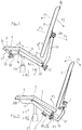
- Figure 1 shows an overall perspective view of a seat according to the invention.
- FIG. 2 represents a side view of a first embodiment of the invention.
- Figure 3 shows a side view of a second embodiment of the invention.
- Figure 4 shows a side view of a third embodiment of the invention.
- FIG. 5 represents a side view of a fourth embodiment of the invention.
- the present invention relates to a device 1 intended to allow a person to sit.
- This device 1 is represented in FIGS. 1 to 5 by a chair 1.
- This chair 1 is of the conventional type since it has a back 2 and a seat 3.
- This seat 3 also has characteristics which are known and clearly visible in FIG. 2.
- This seat 3 consists of two support planes forming between them an obtuse angle ⁇ downwards.
- This angle ⁇ corresponds to the inclination of the second plane 5 of the seat 3 with the horizontal.
- the foreground 4 of the seat 3 has a position which is substantially horizontal. It is intended to receive the femurs of a user.
- the second plane 5 of the seat 3 is, in turn, inclined against the backrest with respect to the backrest 2. This second plane 5 is intended to receive the user's ischia.
- the second plane 5 forms with the backrest 2 an acute angle ⁇ .
- the backrest 2 forms, for its part, an acute angle ⁇ with respect to the vertical.
- the two angles ⁇ and ⁇ can therefore be adjusted in order to obtain an angle a that is well suited to the morphology of the user.
- the adjustment of the angles ⁇ and ⁇ also allows the depth adjustment of the second plane 5 relative to the backrest 2, always with the aim of marrying the shapes of the pelvis of said user as well as possible.
- This figure 2 shows four adjustment possibilities.
- the backrest 2 can also be adjusted in depth with respect to the seat 3. This adjustment when carried out for the entire backrest 2, is done according to F3. When the adjustment is made, on the contrary, towards the rear, it is carried out according to F4. This adjustment makes it possible to increase or decrease the length of the second plane 5 of the seat 3.
- This adjustment is made according to F5 when the rear end of the second plane 5 is directed upwards and according to F6 when this rear end is directed downwards.
- These adjustment means can be angular as regards the position of the backrest 2 relative to the seat 3 but also as regards the second plane 5 of the seat 3 relative to the first plane 4.
- the adjustment means can also be in depth as regards the position of the backrest 2 relative to the seat 3 but also means for adjusting the height of all of said seat 3 or of all of the chair 1.
- the two adjustment angles are ⁇ and ⁇ , made up on the one hand, by a movable segment (second plane 5 for ⁇ and backrest 2 for ⁇ ) and on the other hand, by a fixed reference (the horizontal for ⁇ and the vertical for ⁇ ).
- ⁇ is the angle of adjustment of the seat 3 and ⁇ is that of the backrest 2.
- the two mobile segments previously described, define the angle ⁇ .
- FIGS. 2 to 5 which are four different embodiments of the invention, there are common points.
- the most important point consists in the presence of a hinge pin 6 or 16 at the level of the frame 27, 28, 29 or 30 of the device 1.
- This articulation axis 6 or 16 is present at the interface between the first plane 4 and the second plane 5 of said seat 3.
- the adjustment can be carried out using adjustment screws referenced 7 to 12 which have a free end which can either be supported or secured while remaining movable in rotation about its longitudinal axis at l element to be adjusted and whose threaded body of said screw 7 to 12 cooperates with a threaded fixed point located at the frame 27 to 30 constituting the device 1.
- the screw 7 also allows the angular adjustment according to F1 or F2 of the backrest 2.
- the screw 8 allows the angular adjustment according to F1 or F2 of the backrest 2 while the screw 9 allows the angular adjustment of the second plane 5 of the seat 3 according to F5 or F6.
- the angular adjustment according to F1 or F2 are carried out using two screws 10 and 11 which cooperate.
- the angular adjustment of the second plane 5 of the seat 3 relative to the first plane 4 of said seat 3 is ensured for each adjustment by at least one link 13, one of the ends of which is articulated on the element to be adjusted, that is to say the second plane 5, and the other end of which is movable in a fixed window 14 of the chassis 30, the assembly being able to be locked in position by a clamping means 15.
- This mode embodiment of the invention allows an angular adjustment of the second plane 5 according to F5 or F6.
- the angular adjustment of the second plane 5 of the seat 3 relative to the first plane 4 is provided for each adjustment by a rack rod 17 articulated by one of its ends on the second plan 5 which must be set according to F5 or F6.
- the rack rod 17 cooperates with a fixed lug 18 allowing the blocking in position on the chassis 28.
- the angular adjustment of the second plane 5 of the seat 3 relative to the first plane 4 is provided by another embodiment.
- This is provided by an inverted V-shaped beam 22 which is articulated along an axis 16 relative to the chassis 27 of the device 1.
- One of the arms of the beam 22 is supported or is integral with the second plane 5 of the seat 3 while the other arm comprises a fixed lug 31 which is movable inside a window 32 formed on the frame 27.
- This window 32 longitudinal, extends vertically and delimits the amplitude of adjustment of the second plane 5 relative to the first plane 4.
- the assembly is immobilized in position by means of a locking screw 33.
- the depth adjustment of the backrest 2 is provided by two concentric tubes 19 and 20 which can slide one into the other 20. These two tubes 19 and 20 are locked in position one by 19 relative to the other 20 by means of locking screws 21.
- the tube 20 is in fact made up in the figures by the chassis 28 or 29.
- the other tube 19, for its part, is integral with the backrest 2.
- the height adjustment of the seat 3 is provided in a fairly conventional manner by a jack 23 connecting the frame 27 to 30 to the foot 24 of the device 1 clearly visible in FIG. 1. This allows the adjustment according to F7 or F8.
- the support tube 34 of the backrest 2 and said backrest 2 are articulated together to allow adjustment according to F1 or F2 and are locked in position by means of a simple screw. tightening 26.
- This chair 1 is particularly intended for long-term sitting situations.
Landscapes
- Health & Medical Sciences (AREA)
- Dentistry (AREA)
- General Health & Medical Sciences (AREA)
- Chair Legs, Seat Parts, And Backrests (AREA)
Applications Claiming Priority (2)
| Application Number | Priority Date | Filing Date | Title |
|---|---|---|---|
| FR9407759 | 1994-06-22 | ||
| FR9407759A FR2721488B1 (fr) | 1994-06-22 | 1994-06-22 | Dispositif destiné à s'asseoir comportant de nombreuses possibilités de réglage. |
Publications (2)
| Publication Number | Publication Date |
|---|---|
| EP0688521A1 true EP0688521A1 (de) | 1995-12-27 |
| EP0688521B1 EP0688521B1 (de) | 1999-04-28 |
Family
ID=9464602
Family Applications (1)
| Application Number | Title | Priority Date | Filing Date |
|---|---|---|---|
| EP19950480077 Expired - Lifetime EP0688521B1 (de) | 1994-06-22 | 1995-06-20 | Sitzmöbel mit zahlreichen Einstellmöglichkeiten |
Country Status (3)
| Country | Link |
|---|---|
| EP (1) | EP0688521B1 (de) |
| DE (1) | DE69509302D1 (de) |
| FR (1) | FR2721488B1 (de) |
Cited By (2)
| Publication number | Priority date | Publication date | Assignee | Title |
|---|---|---|---|---|
| GB2342037A (en) * | 1996-05-18 | 2000-04-05 | Slipcatch Ltd | Vehicle safety seat |
| CN112386764A (zh) * | 2020-12-04 | 2021-02-23 | 薛峰 | 一种儿科输液用座椅 |
Citations (6)
| Publication number | Priority date | Publication date | Assignee | Title |
|---|---|---|---|---|
| FR2072977A5 (de) | 1969-12-17 | 1971-09-24 | Giroflex Entwicklungs Ag | |
| US4099774A (en) * | 1977-01-24 | 1978-07-11 | Leggett & Platt, Incorporated | Stenographer's chair |
| DE3138123A1 (de) | 1980-09-29 | 1982-05-27 | Ackermann AB, 11436 Stockholm | Sitzmoebel |
| EP0167435A1 (de) | 1984-06-19 | 1986-01-08 | Albert Palanque | Sitz |
| DE8711717U1 (de) * | 1987-02-17 | 1987-12-23 | Butler, Robert George, Allschwil | Stuhl zur anatomischen Aufrichtung seines Benutzers |
| FR2651657A1 (fr) | 1989-09-08 | 1991-03-15 | Palanque Albert | Siege du type dont la partie d'assise presente deux plans d'appui, le premier est horizontal, le second est en plan incline en contre-pente vers la base du dossier. |
-
1994
- 1994-06-22 FR FR9407759A patent/FR2721488B1/fr not_active Expired - Fee Related
-
1995
- 1995-06-20 EP EP19950480077 patent/EP0688521B1/de not_active Expired - Lifetime
- 1995-06-20 DE DE69509302T patent/DE69509302D1/de not_active Expired - Lifetime
Patent Citations (6)
| Publication number | Priority date | Publication date | Assignee | Title |
|---|---|---|---|---|
| FR2072977A5 (de) | 1969-12-17 | 1971-09-24 | Giroflex Entwicklungs Ag | |
| US4099774A (en) * | 1977-01-24 | 1978-07-11 | Leggett & Platt, Incorporated | Stenographer's chair |
| DE3138123A1 (de) | 1980-09-29 | 1982-05-27 | Ackermann AB, 11436 Stockholm | Sitzmoebel |
| EP0167435A1 (de) | 1984-06-19 | 1986-01-08 | Albert Palanque | Sitz |
| DE8711717U1 (de) * | 1987-02-17 | 1987-12-23 | Butler, Robert George, Allschwil | Stuhl zur anatomischen Aufrichtung seines Benutzers |
| FR2651657A1 (fr) | 1989-09-08 | 1991-03-15 | Palanque Albert | Siege du type dont la partie d'assise presente deux plans d'appui, le premier est horizontal, le second est en plan incline en contre-pente vers la base du dossier. |
Cited By (3)
| Publication number | Priority date | Publication date | Assignee | Title |
|---|---|---|---|---|
| GB2342037A (en) * | 1996-05-18 | 2000-04-05 | Slipcatch Ltd | Vehicle safety seat |
| GB2342037B (en) * | 1996-05-18 | 2000-07-05 | Slipcatch Ltd | Improvements in or relating to seats |
| CN112386764A (zh) * | 2020-12-04 | 2021-02-23 | 薛峰 | 一种儿科输液用座椅 |
Also Published As
| Publication number | Publication date |
|---|---|
| FR2721488A1 (fr) | 1995-12-29 |
| DE69509302D1 (de) | 1999-06-02 |
| EP0688521B1 (de) | 1999-04-28 |
| FR2721488B1 (fr) | 1996-09-06 |
Similar Documents
| Publication | Publication Date | Title |
|---|---|---|
| EP0258156B1 (de) | Klappstuhl mit verstellbarer Rückenlehne und Fussstütze | |
| EP0689784B1 (de) | Ruhesessel | |
| CH626522A5 (en) | Tilting mounting for a chair seat | |
| EP0670241B1 (de) | Sitz mit umklappbarer Armlehne | |
| EP0816160A1 (de) | Kindersitz mit neigbarer Rückenlehne | |
| FR2616307A1 (fr) | Agencement de controle d'inclinaison pour sieges de bureau | |
| EP0077280B1 (de) | Aufrichtstuhl | |
| EP1488770B1 (de) | Hebestuhl mit automatisch veränderlicher Neigung der Rückenlehne | |
| FR2481091A1 (fr) | Dispositif de montage pour siege du type fauteuil | |
| EP0688521B1 (de) | Sitzmöbel mit zahlreichen Einstellmöglichkeiten | |
| CH638102A5 (fr) | Appareil de sustentation pour supporter une personne dans l'eau. | |
| WO2002047513A1 (fr) | Fauteuil multi-positions | |
| WO2018104595A1 (fr) | Dispositif d'appui antérieur pour les membres inférieurs | |
| FR2555877A3 (fr) | Fauteuil reglable | |
| EP0531208B1 (de) | Steharbeitssitz | |
| CH618331A5 (en) | Chair with movable back and seat | |
| EP0572345B1 (de) | Armlehne für einen Vordersitz eines Fahrzeuges | |
| EP1530928B1 (de) | Zusammenklappbarer Stuhl mit einem niedrigen Profil in der zusammengeklappten Position | |
| FR2730146A1 (fr) | Fauteuil de relaxation | |
| EP1722657B1 (de) | Sitz mit getrennt verstellbarer rückenlehne und sitzteil und einer verstellbaren sitztiefe | |
| FR2490086A1 (fr) | Fauteuil transformable en transatlantique avec soutien tournant et appuis-tete separes rabattables | |
| FR2641453A1 (fr) | Fauteuil de repos | |
| FR2847211A1 (fr) | Siege de vehicule automobile | |
| FR3079119A1 (fr) | Dispositif d’aide au passage de la position assise a la position debout, et inversement, plateforme de mobilite pour siege comprenant un tel dispositif, et siege roulant | |
| EP0774222A1 (de) | Stuhl, welcher an die Körperform des Benutzers anpassbar ist |
Legal Events
| Date | Code | Title | Description |
|---|---|---|---|
| PUAI | Public reference made under article 153(3) epc to a published international application that has entered the european phase |
Free format text: ORIGINAL CODE: 0009012 |
|
| AK | Designated contracting states |
Kind code of ref document: A1 Designated state(s): DE FR GB IT |
|
| 17P | Request for examination filed |
Effective date: 19960116 |
|
| 17Q | First examination report despatched |
Effective date: 19970402 |
|
| GRAG | Despatch of communication of intention to grant |
Free format text: ORIGINAL CODE: EPIDOS AGRA |
|
| GRAG | Despatch of communication of intention to grant |
Free format text: ORIGINAL CODE: EPIDOS AGRA |
|
| GRAH | Despatch of communication of intention to grant a patent |
Free format text: ORIGINAL CODE: EPIDOS IGRA |
|
| GRAH | Despatch of communication of intention to grant a patent |
Free format text: ORIGINAL CODE: EPIDOS IGRA |
|
| GRAA | (expected) grant |
Free format text: ORIGINAL CODE: 0009210 |
|
| AK | Designated contracting states |
Kind code of ref document: B1 Designated state(s): DE FR GB IT |
|
| PG25 | Lapsed in a contracting state [announced via postgrant information from national office to epo] |
Ref country code: IT Free format text: LAPSE BECAUSE OF FAILURE TO SUBMIT A TRANSLATION OF THE DESCRIPTION OR TO PAY THE FEE WITHIN THE PRESCRIBED TIME-LIMIT;WARNING: LAPSES OF ITALIAN PATENTS WITH EFFECTIVE DATE BEFORE 2007 MAY HAVE OCCURRED AT ANY TIME BEFORE 2007. THE CORRECT EFFECTIVE DATE MAY BE DIFFERENT FROM THE ONE RECORDED. Effective date: 19990428 Ref country code: GB Free format text: LAPSE BECAUSE OF FAILURE TO SUBMIT A TRANSLATION OF THE DESCRIPTION OR TO PAY THE FEE WITHIN THE PRESCRIBED TIME-LIMIT Effective date: 19990428 Ref country code: FR Free format text: THE PATENT HAS BEEN ANNULLED BY A DECISION OF A NATIONAL AUTHORITY Effective date: 19990428 |
|
| REF | Corresponds to: |
Ref document number: 69509302 Country of ref document: DE Date of ref document: 19990602 |
|
| PG25 | Lapsed in a contracting state [announced via postgrant information from national office to epo] |
Ref country code: DE Free format text: LAPSE BECAUSE OF FAILURE TO SUBMIT A TRANSLATION OF THE DESCRIPTION OR TO PAY THE FEE WITHIN THE PRESCRIBED TIME-LIMIT Effective date: 19990729 |
|
| GBV | Gb: ep patent (uk) treated as always having been void in accordance with gb section 77(7)/1977 [no translation filed] |
Effective date: 19990428 |
|
| PLBE | No opposition filed within time limit |
Free format text: ORIGINAL CODE: 0009261 |
|
| STAA | Information on the status of an ep patent application or granted ep patent |
Free format text: STATUS: NO OPPOSITION FILED WITHIN TIME LIMIT |
|
| 26N | No opposition filed | ||
| REG | Reference to a national code |
Ref country code: FR Ref legal event code: ST |