EP0688729B1 - Müllsammelfahrzeug - Google Patents
Müllsammelfahrzeug Download PDFInfo
- Publication number
- EP0688729B1 EP0688729B1 EP19950890114 EP95890114A EP0688729B1 EP 0688729 B1 EP0688729 B1 EP 0688729B1 EP 19950890114 EP19950890114 EP 19950890114 EP 95890114 A EP95890114 A EP 95890114A EP 0688729 B1 EP0688729 B1 EP 0688729B1
- Authority
- EP
- European Patent Office
- Prior art keywords
- truncated cone
- hollow truncated
- pressure plate
- refuse collection
- collection vehicle
- Prior art date
- Legal status (The legal status is an assumption and is not a legal conclusion. Google has not performed a legal analysis and makes no representation as to the accuracy of the status listed.)
- Expired - Lifetime
Links
- 230000007704 transition Effects 0.000 claims description 4
- 230000000630 rising effect Effects 0.000 claims 2
- 230000006835 compression Effects 0.000 description 12
- 238000007906 compression Methods 0.000 description 12
- 238000000034 method Methods 0.000 description 4
- 238000003825 pressing Methods 0.000 description 4
- 239000002699 waste material Substances 0.000 description 4
- 229910000831 Steel Inorganic materials 0.000 description 3
- 239000010959 steel Substances 0.000 description 3
- 238000004519 manufacturing process Methods 0.000 description 2
- 230000001154 acute effect Effects 0.000 description 1
- 230000003247 decreasing effect Effects 0.000 description 1
- 230000000694 effects Effects 0.000 description 1
- 238000003780 insertion Methods 0.000 description 1
- 230000037431 insertion Effects 0.000 description 1
- 238000003754 machining Methods 0.000 description 1
- 239000000203 mixture Substances 0.000 description 1
- 230000000717 retained effect Effects 0.000 description 1
- 238000003466 welding Methods 0.000 description 1
Images
Classifications
-
- B—PERFORMING OPERATIONS; TRANSPORTING
- B65—CONVEYING; PACKING; STORING; HANDLING THIN OR FILAMENTARY MATERIAL
- B65F—GATHERING OR REMOVAL OF DOMESTIC OR LIKE REFUSE
- B65F3/00—Vehicles particularly adapted for collecting refuse
- B65F3/14—Vehicles particularly adapted for collecting refuse with devices for charging, distributing or compressing refuse in the interior of the tank of a refuse vehicle
- B65F3/22—Vehicles particularly adapted for collecting refuse with devices for charging, distributing or compressing refuse in the interior of the tank of a refuse vehicle with screw conveyors, rotary tanks
Definitions
- the invention relates to a refuse collection vehicle with a collection container which can be driven in rotation in the form of a rotating drum on the vehicle about a horizontal axis and with a cover which is fixed on the rear side of the vehicle on a rigid frame but is arranged in a rotationally fixed but pivotable manner and which has a hollow truncated cone directed into the interior of the rotary drum with a pouring opening and on its lateral surface it has baffle plates and / or its end face compacting devices which, together with helically arranged ribs on the inner wall of the rotary drum, press the garbage into the rotary drum.
- the document AT-PS 361 854 shows such a refuse collection vehicle.
- So-called compact garbage trucks work with rotating rotary drums into which the garbage is introduced and conveyed in the longitudinal direction of the rotary drum by inner ribs.
- a hollow cone with baffles inside the end cover is known, which directs and compactes the garbage from the insertion side into the inside of the drum.
- a screw extending the truncated cone in the direction of the apex is provided as a compression device either as a spiral screw or as a screw with a decreasing pitch towards the tip. Screw surfaces or spiral screws are not easy to manufacture and are therefore expensive.
- the garbage is not optimally compacted due to the inhomogeneous garbage composition with a uniform pressing process, because the position of the individual components does not change substantially and a skeletal structure of the garbage is retained even in a compacted phase.
- a compression unit for a rotating drum waste truck is known, which is based on the design according to AT-PS 361 854 and accordingly has a hollow truncated cone on the inside of a container closing the rotating drum with a baffle plate running helically on the lateral surface.
- This compression unit provides a flat spiral on the end face of the hollow truncated cone, in particular arranged in a continuation of the helical guide plate.
- the end face of the hollow truncated cone constitutes an ellipse as a conic section The end face is thus inclined to the orthogonal bottom surface.
- the invention aims to provide a compacting device of a completely different design, which causes an intermittent pressing process without curved surfaces.
- the compression device comprises flat press plates in the end region of the hollow truncated cone, that the planes of each press plate are oriented so as to rise flatly in relation to a normal plane to the central axis of the hollow cone, that the press plates are lined up in the circumferential direction of the hollow truncated cone and in the transition region from press plate to press plate one step each is provided, the approximately radially oriented end edge of a press plate being higher than the start of the subsequent press plate and the outer edges of the press plates, viewed in the direction of the central axis of the hollow truncated cone, running essentially circularly in the increasing direction.
- the press plates are cut from flat steel sheets and arranged in the manner of desk planes in steps around the central axis of the truncated cone.
- the steps lead to intermittent tensioning and partial relaxation and to the constant dynamic reorientation of the garbage components in the rear area of the garbage truck. This results in a pulsating pressing process, which favors particularly good use of space.
- the pressure plates have essentially the same rise, that is, a constant angle to the central axis of the hollow truncated cone.
- the press plates arranged one behind the other can have end edges that are increasingly higher in the axial direction.
- a cylinder jacket connects in the end region of the hollow truncated cone, which supports the pressure plates on their side facing the jacket of the hollow truncated cone, preferably in the center.
- the end face of the hollow truncated cone corresponds approximately to a drill bit with the appearance of a flat toothing (shepherd toothing).
- the rear that is to say the region of the steps facing the jacket of the hollow truncated cone or also the end cover, is covered by ramp plates arranged in the manner of ramps. Lateral openings are clad by cylindrical sheets, so that there is a closed area over the entire compression device in the end region of the hollow truncated cone.
- a known spiral-shaped guide plate on the jacket of the hollow truncated cone opens with its end lying approximately radially to the central axis of the hollow truncated cone and in its end region in a region of the circumferentially spaced first and last press plate and an axial step to the first press plate , whose starting area is outstanding.
- a flat end plate adjoins the press plate lying on the end face at the outermost end of the compression device and has a greater steepness than the end plate. Your rise in the tangential direction is therefore greater than that of the last press plate.
- the outside diameter of the fixed press plates adjoins the inside wall of the rotating drum, taking into account the web height of the inwardly directed ribs.
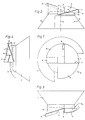
- FIG. 1 shows a top view of a hollow truncated cone with compression device
- FIG. 2 shows a front view
- FIG. 3 shows a rear view
- FIG. 4 shows a side view.
- a fixed cover which closes the rotating drum at the rear, is provided, which carries a hollow truncated cone 1 made of sheet steel, which projects into the interior of the rotating drum.
- Garbage is brought into the interior of the rotary drum through an opening 2 in the jacket of the hollow truncated cone 1, which has ribs on its inner circumferential surface in order to bring the garbage axially away from the opening 2.
- the hollow truncated cone 1 carries in its end region three flat press plates 3, 4, 5, each of which is defined by two intersecting straight lines, one straight line each radial to the central axis 6 of the hollow truncated cone 1 and the other at right angles thereto and at an acute angle to the direction of the Center axis 6 are aligned.
- These press plates 3, 4 and 5 represent desk levels which are arranged around the central axis 6 and each merge into one another by a step 7, 8. This results in a kind of face toothing on the end face of the hollow truncated cone 1.
- the waste reaches the pressing surfaces 3, 4, 5 from a certain degree of filling of the rotary drum and is guided along these surfaces. Compression and relaxation alternate.
- the waste components can be rearranged after a first compression, in order then to be compressed again along the next press plate. This process is repeated again.
- This pulsating compression enables a particularly good compression in cooperation with the rotary drum.
- Wear plates in the form of strips, which follow the edge contour and protrude slightly beyond it, can be screwed or welded onto the quarter-circle-like outer edges of the press plates 3, 4 and 5 made of sheet steel.
- the last press plate 5 in the row carries at the end a flat end plate 9, the rise in the tangential direction of which is greater than that of the press plate 5.
- the pressure plates 3, 4 and 5 and the end plate 9 are connected to a cylinder jacket 10 by welding, which sits centrally on the jacket or on the end face of the truncated cone 1.
- the cylinder jacket 10 supports the pressure plates 3, 4, 5 and the end plate 9 on the underside, that is to say the side facing away from the pressure side.
- the base circle of the cylinder jacket 10 follows a circumferential circle of the truncated cone 1, which is the upper contour of the cylinder jacket 10 the inclination of the pressure plates 3, 4, 5 sawtooth-like.
- the steps 7, 8 are covered in a ramp-like manner by transition plates 11, 12, so that the step effect is primarily shown on the end face of the compression device. Garbage components that get behind the compacting device are transported onwards through the cover plates 11, 12 without the risk of jamming on the rear sides of steps 7, 8.
Landscapes
- Engineering & Computer Science (AREA)
- Mechanical Engineering (AREA)
- Processing Of Solid Wastes (AREA)
- Refuse Receptacles (AREA)
Description
- Die Erfindung betrifft ein Müllsammelfahrzeug mit einem auf dem Fahrzeug um eine horizontale Achse rotierend antreibbaren Sammelbehälter in Form einer Drehtrommel und mit heckseitig auf dem Fahrzeug an einem starren Rahmen rotationsfest, jedoch schwenkbar angeordneten Abschlußdeckel, der einen in das Innere der Drehtrommel gerichteten Hohlkegelstumpf mit einer Einschüttöffnung und an seiner Mantelfläche Leitbleche und bzw. oder seiner Stirnfläche Verdichtungseinrichtungen aufweist, die zusammen mit schraubenlinienförmig angeordneten Rippen an der Innenwand der Drehtrommel den Müll in die Drehtrommel hineindrücken. Das Dokument AT-PS 361 854 zeigt ein solches Müllsammelfahrzeug.
- Sogenannte Preßmüllwagen arbeiten mit rotierenden Drehtrommeln, in welchen der Müll eingebracht und durch innere Rippen in Längsrichtung der Drehtrommel gefördert wird. Ergänzend ist noch ein Hohlkegel mit Leitflächen im Inneren des Abschlußdeckels bekannt, der den Müll von der Einwurfseite in das Trommelinnere leitet und kompaktiert. Dazu ist gemäß der AT-PS 361 854 als Verdichtungseinrichtung eine den Kegelstumpf in Richtung auf den Scheitel verlängernde Schnecke entweder als Spiralschnecke oder als Schraube mit zur Spitze hin abnehmender Ganghöhe vorgesehen. Schraubenflächen oder Spiralschnecken sind nicht leicht herstellbar und demnach teuer. Ferner hat sich gezeigt, daß der Müll infolge der inhomogenen Müllzusammensetzung bei einem gleichmäßigen Preßvorgang nicht optimal kompaktiert wird, weil sich die Position der einzelnen Komponenten zueinander im wesentlichen nicht geändert und eine Skelettstruktur des Mülls auch in einer verdichteten Phase erhalten bleibt.
- Aus der AT-PS 396 915 ist eine Verdichtungseinheit für einen Drehtrommelmüllwagen bekannt, der von der Ausführung nach der AT-PS 361 854 ausgeht und demnach an der Innenseite eines die Drehtrommel abschließenden Behälters einen Hohlkegelstumpf mit einem schraubenlinienförmig auf der Mantelfläche verlaufenden Leitblech aufweist. Diese Verdichtungseinheit sieht an der Stirnfläche des Hohlkegelstumpfes eine ebene, insbesondere in Fortsetzung des schraubenlinienförmig verlaufenden Leitbleches angeordnete Spirale vor. Ferner stellt die Stirnfläche des Hohlkegelstumpfes als Kegelschnitt eine Ellipse dar. Die Stirnfläche ist also zur orthogonalen Bodenfläche schräggestellt. Die Herstellung einer Spirale, auch wenn sie in der Ebene liegt, ist aufwendig, weil Schraubenflächen einer komplexen Bearbeitung bedürfen. Dies trifft auch in besonderem Maße dann zu, wenn Bereiche der ebenen Spirale abgenützt sind und nachbearbeitet oder ausgetauscht werden müssen.
- Diese Aufgabe wird durch die im Anspruch 1 angegebene Erfindung gelöst.
- Die Erfindung zielt darauf ab, eine Verdichtungseinrichtung völlig anderer Bauart anzugeben, die ohne gekrümmte Flächen einen intermittierenden Preßvorgang bewirkt. Dies wird dadurch erreicht, daß die Verdichtungseinrichtung ebene Preßplatten im Stirnbereich des Hohlkegelstumpfes umfaßt, daß die Ebenen jeder Preßplatte gegenüber einer Normalebene zur Mittelachse des Hohlkegels gleichsinnig flach ansteigend orientiert sind, daß die Preßplatten in Umfangsrichtung des Hohlkegelstumpfes aneinandergereiht sind und im Übergangsbereich von Preßplatte zu Preßplatte jeweils eine Stufe vorgesehen ist, wobei in ansteigender Richtung die etwa radial ausgerichtete Endkante einer Preßplatte höher liegt als der Anfang der anschließenden Preßplatte und die Außenkanten der Preßplatten, in Richtung der Mittelachse des Hohlkegelstumpfes gesehen, im wesentlichen kreisförmig verlaufen. Die Preßplatten sind aus ebenen Stahlblechen ausgeschnitten und in der Art von Pultebenen stufenartig um die Mittelachse des Hohlkegelstumpfes herum angeordnet. Die Stufen führen zu einem intermittierenden Spannen und teilweisen Entspannen und zur ständigen dynamischen Neuorientierung der Müllkomponenten im Heckbereich des Müllwagens. Daraus resultiert ein pulsierender Preßvorgang, der eine besonders gute Raumausnutzung begünstigt. Die Preßplatten weisen im wesentlichen gleichen Anstieg, also einen gleichbleibenden Winkel zur Mittelachse des Hohlkegelstumpfes auf. Die hintereinander angeordneten Preßplatten können in axialer Richtung zunehmend höher liegende Endkanten aufweisen. Es ist zweckmäßig, wenn im Stirnbereich des Hohlkegelstumpfes ein Zylindermantel anschließt, der die Preßplatten an ihrer dem Mantel des Hohlkegelstumpfes zugewandten Seite, vorzugsweise mittig, unterstützt. Dadurch entspricht die Stirnseite des Hohlkegelstumpfes etwa einer Bohrkrone mit dem Erscheinungsbild einer flächigen Verzahnung (Hirt-Verzahnung). Die Rückseite, also der dem Mantel des Hohlkegelstumpfes oder auch dem Abschlußdeckel zugewandte Bereich der Stufen ist durch rampenartig angeordnete Übergangsbleche abgedeckt. Seitliche Öffnungen sind durch zylindrische Bleche verkleidet, sodaß sich eine geschlossene Fläche über die gesamte Verdichtungseinrichtung im Stirnbereich des Hohlkegelstumpfes ergibt. Es ist zweckmäßig, wenn ein an sich bekanntes spiralförmig verlaufendes Leitblech auf dem Mantel des Hohlkegelstumpfes mit seinem etwa radial zur Mittelachse des Hohlkegelstumpfes und in dessen Stirnbereich liegenden Ende in einen Bereich der in Umfangsrichtung beabstandeten ersten und letzten Preßplatte einmündet und eine axiale Stufe zur ersten Preßplatte, deren Anfangsbereich überragend, bildet.
- In einer Weiterbildung der Erfindung ist vorgesehen, daß an die stirnseitig am äußersten Ende der Verdichtungseinrichtung liegenden Preßplatte eine ebene Endplatte stufenlos anschließt und eine größere Steilheit als die Endplatte aufweist. Ihr Anstieg in tangentialer Richtung ist also größer als jener der letzten Preßplatte. Der Außendurchmesser der feststehenden Preßplatten grenzt an die Innenwand der Drehtrommel unter Berücksichtigung der Steghöhe der nach innen gerichteten Rippen an.
- Ein Ausführungsbeispiel des Erfindungsgegenstandes ist in den Zeichnungen dargestellt. Fig. 1 zeigt eine Draufsicht auf einen Hohlkegelstumpf mit Verdichtungseinrichtung, Fig. 2 eine Vorderansicht, Fig. 3 eine Rückansicht und Fig. 4 eine Seitenansicht. Es handelt sich jeweils um Prinzipdarstellungen, wobei beispielsweise ein Anschlußflansch an den Abschlußdeckel der Drehtrommel oder ein Leitblech am Hohlkegelstumpfmantel weggelassen wurden.
- Zum Kompaktierung von Müll in einer Drehtrommel eines Müllsammelfahrzeuges ist ein die Drehtrommel heckseitig abschließender, feststehender Deckel vorgesehen, der einen Hohlkegelstumpf 1 aus Stahlblech trägt, der in das Innere der Drehtrommel hineinragt. Durch eine Öffnung 2 im Mantel des Hohlkegelstumpfes 1 wird Müll in das Innere der Drehtrommel gebracht, die an ihrer inneren Mantelfläche Rippen aufweist, um den Müll axial von der Öffnung 2 wegzubringen. Der Hohlkegelstumpf 1 trägt in seinem Stirnbereich drei ebene Preßplatten 3, 4, 5, die jeweils durch zwei einander schneidende Gerade definiert sind, wobei eine Gerade jeweils radial zur Mittelachse 6 des Hohlkegelstumpfes 1 und die andere rechtwinkelig dazu und in einem spitzen Winkel zur Richtung der genannten Mittelachse 6 ausgerichtet sind. Diese Preßplatten 3, 4 und 5 stellen Pultebenen dar, die rings um die Mittelachse 6 angeordnet sind und jeweils durch eine Stufe 7, 8 ineinander übergehen. Es ergibt sich eine Art Planverzahnung auf der Stirnfläche des Hohlkegelstumpfes 1. Der Müll gelangt ab einem gewissen Füllungsgrad der Drehtrommel auf die Preßflächen 3, 4, 5 und wird entlang dieser Flächen geführt. Kompression und Entspannung wechseln einander ab. Durch die Drehbewegung der Drehtrommel und damit der Komponenten des Mülls und durch die Freiräume im Bereich der Stufen 7, 8 können sich die Müllkomponenten nach einer ersten Kompression neu ordnen, um sodann neuerlich längs der nächsten Preßplatte komprimiert zu werden. Dieser Vorgang wiederholt sich nochmals. Durch diese pulsierende Kompression kann eine besonders gute Verdichtung im Zusammenwirken mit der Drehtrommel erzielt werden.
- An den viertelkreisartigen Außenrändern der aus Stahlblech gefertigten Preßplatten 3, 4, und 5 können Verschleißbleche in Form von Streifen, die der Randkontur folgen und diese etwas überragen, aufgeschraubt oder aufgeschweißt werden. Die letzte Preßplatte 5 in der Reihe trägt am Ende eine ebene Endplatte 9, deren Anstieg in tangentialer Richtung größer ist als der der Preßplatte 5.
- Die Preßplatten 3, 4 und 5 sowie die Endplatte 9 sind mit einem Zylindermantel 10 durch Aufschweißen verbunden, der zentrisch auf dem Mantel oder auf der Stirnfläche des Hohlkegelstumpfes 1 sitzt. Der Zylindermantel 10 unterstützt die Preßplatten 3, 4, 5 und die Endplatte 9 an der Unterseite, also der der Druckseite abgewendeten Seite. Der Basiskreis des Zylindermantels 10 folgt einem Umfangskreis des Hohlkegelstumpfes 1, die obere Kontur des Zylindermantels 10 ist der Neigung der Preßplatten 3, 4, 5 sägezahnartig ausgebildet.
- An der Unterseite der Preßplatten 3, 4, 5 sind die Stufen 7, 8 durch Übergangsbleche 11, 12 rampenartige abgedeckt, sodaß sich der Stufeneffekt in erster Linie an der Stirnseite der Verdichtungseinrichtung zeigt. Müllkomponenten, die hinter der Verdichtungseinrichtung gelangt, werden infolge der Abdeckung durch die Übergangsbleche 11, 12 ohne Staugefahr an den Rückseiten der Stufen 7, 8 weitertransportiert.
Claims (6)
- Müllsammelfahrzeug mit einem auf dem Fahrzeug um eine horizontale Achse rotierend antreibbaren Sammelbehälter in Form einer Drehtrommel und mit heckseitig auf dem Fahrzeug an einem starren Rahmen rotationsfest, jedoch schwenkbar angeordneten Abschlußdeckel, der einen in das Innere der Drehtrommel gerichteten Hohlkegelstumpf (1) mit einer Einschüttöffnung (2) und an seiner Mantelfläche Leitbleche und bzw. oder seiner Stirnfläche Verdichtungseinrichtungen (3, 4, 5) aufweist, die zusammen mit schraubenlinienförmig angeordneten Rippen an der Innenwand der Drehtrommel den Müll in die Drehtrommel hineindrücken, dadurch gekennzeichnet, daß die Verdichtungseinrichtung ebene Preßplatten (3, 4, 5) im Stirnbereich des Hohlkegelstumpfes (1) umfaßt, daß die Ebenen jeder Preßplatte (3, 4, 5) gegenüber einer Normalebene zur Mittelachse des Hohlkegels gleichsinnig flach ansteigend orientiert sind, daß die Preßplatten (3, 4, 5) in Umfangsrichtung des Hohlkegelstumpfes (1) aneinandergereiht sind und im Übergangsbereich von Preßplatte (3, 4, 5) zu Preßplatte (3, 4, 5) jeweils eine Stufe (7, 8) vorgesehen ist, wobei in ansteigender Richtung die etwa radial ausgerichtete Endkante einer Preßplatte (3, 4, 5) höher liegt als der Anfang der anschließenden Preßplatte (3, 4, 5) und die Außenkanten der Preßplatten (3, 4, 5), in Richtung der Mittelachse des Hohlkegelstumpfes (1) gesehen, im wesentlichen kreisförmig verlaufen.
- Müllsammelfahrzeug nach Anspruch 1, dadurch gekennzeichnet, daß die Preßplatten (3, 4, 5) im wesentlichen gleichen Anstieg aufweisen.
- Müllsammelfahrzeug nach den Ansprüchen 1 oder 2, dadurch gekennzeichnet, daß im Stirnbereich des Hohlkegelstumpfes (1) ein Zylindermantel (10) anschließt, der die Preßplatten (3, 4, 5) an ihrer dem Mantel des Hohlkegelstumpfes (1) zugewandten Seite, vorzugsweise mittig, unterstützt.
- Müllsammelfahrzeug nach einem der Ansprüche 1 bis 3, dadurch gekennzeichnet, daß der dem äußeren Mantel des Hohlkegelstumpfes (1) zugewandte Bereich der Stufen (7, 8) durch rampenartig angeordnete Übergangsbleche (11, 12) abgedeckt ist.
- Müllsammelfahrzeug nach einem der Ansprüche 1 bis 4, dadurch gekennzeichnet, daß ein an sich bekanntes spiralförmig verlaufendes Leitblech auf dem Mantel des Hohlkegelstumpfes (1) mit seinem etwa radial zur Mittelachse (6) des Hohlkegelstumpfes (1) und in dessen Stirnbereich liegenden Ende in einen Bereich der in Umfangsrichtung beabstandeten ersten und letzten Preßplatte (3, 5) einmündet und eine axiale Stufe zur ersten Preßplatte (3), deren Anfangsbereich überragend, bildet.
- Müllsammelfahrzeug nach einem der Ansprüche 1 bis 5, dadurch gekennzeichnet, daß an die vom Hohlkegelstumpf (1) stirnseitig am weitesten entfernte Preßplatte (5) eine ebene Endplatte (9) stufenlos anschließt und eine größere Steilheit als die Preßplatte (5) aufweist.
Applications Claiming Priority (2)
| Application Number | Priority Date | Filing Date | Title |
|---|---|---|---|
| AT123394A AT401041B (de) | 1994-06-22 | 1994-06-22 | Müllsammelfahrzeug |
| AT1233/94 | 1994-06-22 |
Publications (2)
| Publication Number | Publication Date |
|---|---|
| EP0688729A1 EP0688729A1 (de) | 1995-12-27 |
| EP0688729B1 true EP0688729B1 (de) | 1997-09-10 |
Family
ID=3509486
Family Applications (1)
| Application Number | Title | Priority Date | Filing Date |
|---|---|---|---|
| EP19950890114 Expired - Lifetime EP0688729B1 (de) | 1994-06-22 | 1995-06-21 | Müllsammelfahrzeug |
Country Status (6)
| Country | Link |
|---|---|
| EP (1) | EP0688729B1 (de) |
| AT (1) | AT401041B (de) |
| CZ (1) | CZ162795A3 (de) |
| DE (1) | DE59500632D1 (de) |
| ES (1) | ES2109801T3 (de) |
| SK (1) | SK280037B6 (de) |
Families Citing this family (1)
| Publication number | Priority date | Publication date | Assignee | Title |
|---|---|---|---|---|
| CN106742986A (zh) * | 2017-04-01 | 2017-05-31 | 扬州川机械有限公司 | 一种后装旋转压缩式垃圾车 |
Family Cites Families (4)
| Publication number | Priority date | Publication date | Assignee | Title |
|---|---|---|---|---|
| US3104022A (en) * | 1960-09-07 | 1963-09-17 | Keller & Knappich Gmbh | Garbage disposal means |
| DE2802653C3 (de) | 1978-01-21 | 1981-11-05 | Industrie-Werke Karlsruhe Augsburg Ag, 7500 Karlsruhe | Fahrzeug zur Beförderung von Müll oder anderem Schüttgut |
| DE3930967A1 (de) * | 1988-09-19 | 1990-03-29 | Mut Maschinen Umwelttechnik | Muellfahrzeug mit rotierendem sammelbehaelter |
| AT396915B (de) * | 1991-07-19 | 1993-12-27 | Pickart Josef | Fahrzeug zum transport von müll od. dgl. |
-
1994
- 1994-06-22 AT AT123394A patent/AT401041B/de not_active IP Right Cessation
-
1995
- 1995-06-20 CZ CZ951627A patent/CZ162795A3/cs unknown
- 1995-06-21 EP EP19950890114 patent/EP0688729B1/de not_active Expired - Lifetime
- 1995-06-21 ES ES95890114T patent/ES2109801T3/es not_active Expired - Lifetime
- 1995-06-21 DE DE59500632T patent/DE59500632D1/de not_active Expired - Fee Related
- 1995-06-21 SK SK817-95A patent/SK280037B6/sk unknown
Also Published As
| Publication number | Publication date |
|---|---|
| ATA123394A (de) | 1995-10-15 |
| ES2109801T3 (es) | 1998-01-16 |
| CZ162795A3 (en) | 1996-01-17 |
| SK280037B6 (sk) | 1999-07-12 |
| AT401041B (de) | 1996-05-28 |
| EP0688729A1 (de) | 1995-12-27 |
| SK81795A3 (en) | 1996-05-08 |
| DE59500632D1 (de) | 1997-10-16 |
Similar Documents
| Publication | Publication Date | Title |
|---|---|---|
| DE69123601T2 (de) | Spindelpresse | |
| DE69612740T2 (de) | Fraktioniervorrichtung | |
| DE3047013C2 (de) | Dispergervorrichtung für die Aufbereitung von Altpapierstoff | |
| DE102008057137B4 (de) | Kompaktiervorrichtung | |
| DE69519862T2 (de) | Mühle, verfahren für die herstellung von knochentransplantationsmaterial und verwendung einer mühle für solch eine herstellung | |
| DE4446244A1 (de) | Entsafter | |
| WO2015032596A1 (de) | Vorrichtung und verfahren zum aufbereiten von faserhaltigen verbundwerkstoffen | |
| DE102014105672B4 (de) | Vorrichtung zum Zusammendrücken von Behältern | |
| EP0529221A1 (de) | Zerkleinerungsvorrichtung | |
| DE20214115U1 (de) | Siebmaschine | |
| DE69924416T2 (de) | Entwässerungsschneckenpresse für Feuchtigkeit enthaltende Produkte | |
| DE2918519C2 (de) | ||
| DE3834206A1 (de) | Vorrichtung zum zerkleinern von haus- und gartenabfaellen, von stroh, von obst usw. | |
| EP0565823B1 (de) | Entwässerungspresse für durch Komprimieren entwässerbare Stoffe | |
| DE60002974T2 (de) | Vorrichtung zum Aufreissen von Säcken für einmalige Verwendung | |
| AT401041B (de) | Müllsammelfahrzeug | |
| DE2810359A1 (de) | Vorrichtung zum selektiven sortieren von materialschnitzeln | |
| EP0037036B1 (de) | Rotorenschere für die Abfallzerkleinerung | |
| EP0211230B1 (de) | Vorrichtung zum Mischen von Feststoffen und Flüssigkeiten | |
| DE2802653A1 (de) | Drehtrommel-sammelbehaelter mit ausraeum- und presschnecke | |
| DE3012090A1 (de) | Rohrpresse zur herstellung eines betonrohres | |
| DE60120229T2 (de) | Vorrichtung zum desintegrieren und kompaktieren von cellulosehaltigem material | |
| DE2655314A1 (de) | Abfallverdichter | |
| DE19652323A1 (de) | Schneidsatz für eine Schneckenfördereinrichtung | |
| DE4122918B4 (de) | Vorrichtung zum Quetschen und/oder Mahlen von Körnern |
Legal Events
| Date | Code | Title | Description |
|---|---|---|---|
| PUAI | Public reference made under article 153(3) epc to a published international application that has entered the european phase |
Free format text: ORIGINAL CODE: 0009012 |
|
| AK | Designated contracting states |
Kind code of ref document: A1 Designated state(s): DE ES FR IT |
|
| 17P | Request for examination filed |
Effective date: 19960503 |
|
| GRAG | Despatch of communication of intention to grant |
Free format text: ORIGINAL CODE: EPIDOS AGRA |
|
| 17Q | First examination report despatched |
Effective date: 19961031 |
|
| GRAH | Despatch of communication of intention to grant a patent |
Free format text: ORIGINAL CODE: EPIDOS IGRA |
|
| GRAH | Despatch of communication of intention to grant a patent |
Free format text: ORIGINAL CODE: EPIDOS IGRA |
|
| GRAA | (expected) grant |
Free format text: ORIGINAL CODE: 0009210 |
|
| AK | Designated contracting states |
Kind code of ref document: B1 Designated state(s): DE ES FR IT |
|
| REF | Corresponds to: |
Ref document number: 59500632 Country of ref document: DE Date of ref document: 19971016 |
|
| ET | Fr: translation filed | ||
| ITF | It: translation for a ep patent filed | ||
| REG | Reference to a national code |
Ref country code: ES Ref legal event code: FG2A Ref document number: 2109801 Country of ref document: ES Kind code of ref document: T3 |
|
| PLBE | No opposition filed within time limit |
Free format text: ORIGINAL CODE: 0009261 |
|
| STAA | Information on the status of an ep patent application or granted ep patent |
Free format text: STATUS: NO OPPOSITION FILED WITHIN TIME LIMIT |
|
| 26N | No opposition filed | ||
| REG | Reference to a national code |
Ref country code: FR Ref legal event code: TP |
|
| PGFP | Annual fee paid to national office [announced via postgrant information from national office to epo] |
Ref country code: FR Payment date: 20010622 Year of fee payment: 7 |
|
| PGFP | Annual fee paid to national office [announced via postgrant information from national office to epo] |
Ref country code: DE Payment date: 20010626 Year of fee payment: 7 |
|
| PGFP | Annual fee paid to national office [announced via postgrant information from national office to epo] |
Ref country code: ES Payment date: 20010731 Year of fee payment: 7 |
|
| REG | Reference to a national code |
Ref country code: ES Ref legal event code: PC2A |
|
| PG25 | Lapsed in a contracting state [announced via postgrant information from national office to epo] |
Ref country code: ES Free format text: LAPSE BECAUSE OF NON-PAYMENT OF DUE FEES Effective date: 20020622 |
|
| PG25 | Lapsed in a contracting state [announced via postgrant information from national office to epo] |
Ref country code: DE Free format text: LAPSE BECAUSE OF NON-PAYMENT OF DUE FEES Effective date: 20030101 |
|
| PG25 | Lapsed in a contracting state [announced via postgrant information from national office to epo] |
Ref country code: FR Free format text: LAPSE BECAUSE OF NON-PAYMENT OF DUE FEES Effective date: 20030228 |
|
| REG | Reference to a national code |
Ref country code: FR Ref legal event code: ST |
|
| REG | Reference to a national code |
Ref country code: ES Ref legal event code: FD2A Effective date: 20030711 |
|
| PG25 | Lapsed in a contracting state [announced via postgrant information from national office to epo] |
Ref country code: IT Free format text: LAPSE BECAUSE OF NON-PAYMENT OF DUE FEES Effective date: 20050621 |