EP0688906A1 - Grundwasserdrainagevorrichtung - Google Patents
Grundwasserdrainagevorrichtung Download PDFInfo
- Publication number
- EP0688906A1 EP0688906A1 EP94304620A EP94304620A EP0688906A1 EP 0688906 A1 EP0688906 A1 EP 0688906A1 EP 94304620 A EP94304620 A EP 94304620A EP 94304620 A EP94304620 A EP 94304620A EP 0688906 A1 EP0688906 A1 EP 0688906A1
- Authority
- EP
- European Patent Office
- Prior art keywords
- drainage
- strip
- network
- ground
- ground water
- Prior art date
- Legal status (The legal status is an assumption and is not a legal conclusion. Google has not performed a legal analysis and makes no representation as to the accuracy of the status listed.)
- Granted
Links
- 239000003673 groundwater Substances 0.000 title claims abstract description 12
- XLYOFNOQVPJJNP-UHFFFAOYSA-N water Substances O XLYOFNOQVPJJNP-UHFFFAOYSA-N 0.000 claims abstract description 24
- 239000000835 fiber Substances 0.000 claims abstract description 21
- 239000000463 material Substances 0.000 claims abstract description 15
- 238000000465 moulding Methods 0.000 claims abstract description 8
- 238000000034 method Methods 0.000 claims abstract description 5
- 238000009434 installation Methods 0.000 claims description 3
- 238000010276 construction Methods 0.000 description 14
- 229920000728 polyester Polymers 0.000 description 11
- -1 polyethylene Polymers 0.000 description 8
- 239000004698 Polyethylene Substances 0.000 description 7
- 229920000573 polyethylene Polymers 0.000 description 7
- 229910000831 Steel Inorganic materials 0.000 description 2
- 239000011148 porous material Substances 0.000 description 2
- 239000010959 steel Substances 0.000 description 2
- 239000004743 Polypropylene Substances 0.000 description 1
- 230000006750 UV protection Effects 0.000 description 1
- 230000035508 accumulation Effects 0.000 description 1
- 238000009825 accumulation Methods 0.000 description 1
- 230000002411 adverse Effects 0.000 description 1
- 230000000694 effects Effects 0.000 description 1
- 239000004744 fabric Substances 0.000 description 1
- 239000006260 foam Substances 0.000 description 1
- 239000012466 permeate Substances 0.000 description 1
- 229920001155 polypropylene Polymers 0.000 description 1
- 239000011178 precast concrete Substances 0.000 description 1
- 239000011347 resin Substances 0.000 description 1
- 229920005989 resin Polymers 0.000 description 1
- 230000000717 retained effect Effects 0.000 description 1
- 239000002689 soil Substances 0.000 description 1
- 239000000126 substance Substances 0.000 description 1
- 239000002352 surface water Substances 0.000 description 1
- 238000003466 welding Methods 0.000 description 1
Images


Classifications
-
- E—FIXED CONSTRUCTIONS
- E02—HYDRAULIC ENGINEERING; FOUNDATIONS; SOIL SHIFTING
- E02D—FOUNDATIONS; EXCAVATIONS; EMBANKMENTS; UNDERGROUND OR UNDERWATER STRUCTURES
- E02D31/00—Protective arrangements for foundations or foundation structures; Ground foundation measures for protecting the soil or the subsoil water, e.g. preventing or counteracting oil pollution
- E02D31/02—Protective arrangements for foundations or foundation structures; Ground foundation measures for protecting the soil or the subsoil water, e.g. preventing or counteracting oil pollution against ground humidity or ground water
-
- E—FIXED CONSTRUCTIONS
- E02—HYDRAULIC ENGINEERING; FOUNDATIONS; SOIL SHIFTING
- E02B—HYDRAULIC ENGINEERING
- E02B11/00—Drainage of soil, e.g. for agricultural purposes
-
- E—FIXED CONSTRUCTIONS
- E02—HYDRAULIC ENGINEERING; FOUNDATIONS; SOIL SHIFTING
- E02D—FOUNDATIONS; EXCAVATIONS; EMBANKMENTS; UNDERGROUND OR UNDERWATER STRUCTURES
- E02D3/00—Improving or preserving soil or rock, e.g. preserving permafrost soil
- E02D3/02—Improving by compacting
- E02D3/10—Improving by compacting by watering, draining, de-aerating or blasting, e.g. by installing sand or wick drains
Definitions
- This invention relates to a ground water drainage system using an underground network with drainage strips by which a three-dimensional drainage network for diverting water can be formed in the ground, thereby allowing rain water and underground water accumulated in the ground a means of drainage for the purposes of alleviating hydraulic pressure exerted in the ground, increasing ground stability and preventing earth movements from occurring in a construction site, as example.
- Network materials used for ground constructions comprise a synthetic polymeric material forming a network or mesh configuration, wherein said synthetic network material is formed by elongating thin strips of polymeric material using a prestressing machine as shown in Figure 1 or fabricated from high tensile-strength polyester fibre bundles wrapped with a polyethylene layer as shown in Figures 2 and 3. The friction generated between the ground and the network prevents deformation of the ground and earth movements from occurring in a construction site.
- the conventional systems installed in the ground structure in conjunction with a ground construction project allowing rain water and underground water accumulated in the ground to be drained for the purposes of alleviating hydraulic pressure exerted on the ground, increasing ground stability and preventing earth movements from occurring in the construction site typically involve the employment of underground drainage devices as shown, for example, in Figure 4, used at the bottom of said ground structure, so that water can be effectively drained from the ground system.
- the drainage pipes installed in the ground system are typically three to four meters apart, which is undesirable in that the process of installing these pipes is tedious and water cannot be effectively removed by these pipes because of the distance between them. This causes the ground to become muddy and the ground pressure to build up quickly, resulting in earth movements in a construction site.
- the present invention seeks to provide a drainage network in which each strip forming the network for use in a ground construction has one or more drainage belts for embedding in the soil to form a three-dimensional drainage network system in the ground structure for draining rain water and underground water accumulated in the ground and to thereby alleviate hydraulic pressure exerted on the ground thus increasing ground stability and preventing earth movement from occurring in a construction site.
- the principal object of this invention is to provide a drainage network by means of which an effective three-dimensional drainage system can be established in ground structures.
- Another object of this invention is to provide a drainage network that can be installed efficiently to replace typical conventional piping systems such as the so-called “French pipe” systems and by which rain water and underground water will be drained substantially completely and quickly.
- a ground water drainage network comprising a number of strips for embedding in the ground and forming a water permeable network or mesh structure characterised in that each drainage strip comprises one or more high tensile-strength fibre bundles and one or more drainage belts, said one or more high tensile-strength fibre bundles being embedded in a polymeric material by a moulding process thereby forming said strip, the said strip having a recessed or channelled portion with one or more water permeable drainage belts inserted therein.
- the drainage network 5 is formed from a multiple number of drainage strips 50 in a network configuration, each strip being in parallel spaced configuration and forming a coplanar mat-like structure with transverse support backing slats 51 forming cross-bearers which may be connected to the strips 50 at the cross-over points; the connection here may be by mechanical means, such as pins, or by welding or bonding.
- each drainage strip 50 comprises a channelled strip 511, two pairs of high tensile strength polyester fibre bundles 512 and 513, and a drainage belt 514.
- the parts of the strip 501 defining the channel 502 are provided with two sets of high tensile-strength polyester fibre bundles 512 and 513 embedded in the strip 511 and, as shown in Figure 6-1, this is achieved by moulding using a moulding apparatus in which the two pairs of high tensile-strength polyester fibre bundles 512 and 513 separated by an appropriate distance are embedded in a polyethylene material.
- the centre of said strip 501 is equipped with channel 502 containing a drainage belt 514 inserted therein by an apparatus to thereby form the assembled drainage strip 50.
- a polyethylene material forms the base to contain the two sets of high tensile-strength polyester fibre bundles 512 and 513 separated by an appropriate distance between which the channel 502 is located.
- the high tensile-strength polyester fibre bundles 512 and 513 inside said strip 501 have excellent properties for the purpose, such as durability, UV resistance, chemical resistance, bio-resistance and tensile strength. As shown in Figure 6-2, said fibre material possesses a tensile strength comparable to steel when elongated below approximately 20%.
- the function of polyethylene strip 511 is to maintain the shape of said strip and to prevent said high tensile-strength polyester fibre bundles 512 and 513 from being damaged during installation.
- the drainage belt 514 inside the slot 502 at the centre of said strip provides the means by which surface water and underground water can be drained from the ground.
- the drainage network of this invention possesses the following advantages:
- the device has a network configuration by which said drainage network can interlock with the ground to form a unit system. Additionally, forces exerted in the ground can be transferred readily to and be borne by the drainage network which is equipped with the high-tensile strength fibre bundles.
- Conventional high tensile-strength materials are designed to separate the ground into layers. Such configuration is undesirable in that water and air are retained in the earth below the high tensile-strength material. As a result, not only is the earth not strengthened, the safety and stability of the entire ground system is also jeopardised.
- the present network is employed, the continuity and homogeneity of the ground is not interrupted. Thus the problems described above are avoided.
- the drainage network 8 pertaining to this example is formed of a multiple number of drainage strips 80 in a network configuration.
- the strips 80 are interconnected by the slats 51.
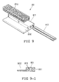
- said drainage strip 80 has a side channel 802 in the strip 811, one pair of high tensile-strength polyester fibre bundles 812 and a drainage belt 813.
- the strip 801 with one pair of high tensile-strength polyester fibre bundles 812 embedded therein and as shown in Figure 9-1 is formed by moulding using a moulding device in which the high tensile-strength polyester fibre bundles 812 are embedded in a polyethylene material.
- One side of said strip 801 is equipped with the channel 802, and a drainage belt 813 is inserted directly into said channel 802 in said strip 801, thereby forming said drainage strip 80.
- the drainage networks described in Examples 1 and 2 provide substantially identical results and are different only in the shape and configuration of the drainage strip.
- the drainage belt employed in the present drainage networks is a porous material that allows water to permeate freely and may be formed from polypropylene or polyethylene in the form of a foam or sponge of open-pore construction.
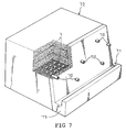
- the drainage network 5 equipped with said drainage belt is set in the ground 72 as shown in Figure 7 as example, rain water collected and underground water can be diverted to pipes 70 and drained away quickly through gully 71 of pre-cast concrete edge 73, thereby alleviating hydraulic pressure exerted on the ground, increasing ground stability and preventing earth movement from occurring in the construction site.
- the network comprises a number of units 5 one above the other.
- the complete network is so constructed that a large sheet thereof may be rolled-up for delivery to the site and thereafter installed by unrolling.
- the drainage network in which the drainage belt is inserted into the drainage strip has other advantages. Specifically, ground equipped with the present drainage network can be relieved of rain water and underground water accumulations. Additionally, the installation of underground drainage pipes (French drainage pipes) can be avoided, thereby reducing construction costs.
- underground drainage pipes Frnch drainage pipes
Landscapes
- Engineering & Computer Science (AREA)
- Life Sciences & Earth Sciences (AREA)
- Structural Engineering (AREA)
- General Engineering & Computer Science (AREA)
- Civil Engineering (AREA)
- Agronomy & Crop Science (AREA)
- Environmental & Geological Engineering (AREA)
- General Life Sciences & Earth Sciences (AREA)
- Mining & Mineral Resources (AREA)
- Paleontology (AREA)
- Mechanical Engineering (AREA)
- Hydrology & Water Resources (AREA)
- Soil Sciences (AREA)
- Investigation Of Foundation Soil And Reinforcement Of Foundation Soil By Compacting Or Drainage (AREA)
- Sewage (AREA)
Priority Applications (3)
| Application Number | Priority Date | Filing Date | Title |
|---|---|---|---|
| US08/198,021 US5567077A (en) | 1994-02-17 | 1994-02-17 | Drainage network |
| DE1994626150 DE69426150T2 (de) | 1994-06-24 | 1994-06-24 | Grundwasserdrainagevorrichtung |
| EP94304620A EP0688906B1 (de) | 1994-02-17 | 1994-06-24 | Grundwasserdrainagevorrichtung |
Applications Claiming Priority (2)
| Application Number | Priority Date | Filing Date | Title |
|---|---|---|---|
| US08/198,021 US5567077A (en) | 1994-02-17 | 1994-02-17 | Drainage network |
| EP94304620A EP0688906B1 (de) | 1994-02-17 | 1994-06-24 | Grundwasserdrainagevorrichtung |
Publications (2)
| Publication Number | Publication Date |
|---|---|
| EP0688906A1 true EP0688906A1 (de) | 1995-12-27 |
| EP0688906B1 EP0688906B1 (de) | 2000-10-18 |
Family
ID=26137164
Family Applications (1)
| Application Number | Title | Priority Date | Filing Date |
|---|---|---|---|
| EP94304620A Expired - Lifetime EP0688906B1 (de) | 1994-02-17 | 1994-06-24 | Grundwasserdrainagevorrichtung |
Country Status (2)
| Country | Link |
|---|---|
| US (1) | US5567077A (de) |
| EP (1) | EP0688906B1 (de) |
Cited By (7)
| Publication number | Priority date | Publication date | Assignee | Title |
|---|---|---|---|---|
| EP1010812A1 (de) | 1998-12-17 | 2000-06-21 | Jesse Yang | Grundwasserdrainagesystem |
| EP1106739A3 (de) * | 1999-12-11 | 2002-10-02 | Linear Composites Limited | Kombiniertes Bodenbewehrungs- und Dränagegitter |
| KR100811479B1 (ko) * | 2006-07-25 | 2008-03-10 | 김순용 | 지반보강재 |
| EP2281950A1 (de) | 2009-06-26 | 2011-02-09 | Pedro Gustavo Figuerola Garcia De La Pastora | System zur Behandlung von unterirdischen Flüssigkeiten |
| CN102322054A (zh) * | 2011-06-30 | 2012-01-18 | 中交四航工程研究院有限公司 | 超软土浅表层间歇性强抽排水结合短期晾晒的处理方法 |
| GB2483649A (en) * | 2010-09-14 | 2012-03-21 | Abg Ltd | Drainage component for use in Composite Material |
| EP2941506A4 (de) * | 2013-01-04 | 2016-11-02 | Sources Unltd L Llc | Feuchtigkeitsregelungsnetz |
Families Citing this family (7)
| Publication number | Priority date | Publication date | Assignee | Title |
|---|---|---|---|---|
| US6663323B1 (en) * | 2002-11-18 | 2003-12-16 | Mark A. Boys | Retaining wall block and drainage system |
| US7413381B1 (en) | 2007-01-05 | 2008-08-19 | Bracone Jr Dominic J | Septic system drain field |
| US20090007509A1 (en) * | 2007-07-05 | 2009-01-08 | Jordan Todd A | Insulated board having an integral drain |
| USD616970S1 (en) | 2009-03-13 | 2010-06-01 | Fiskars Brand, Inc. | Downspout diverter |
| US8033058B2 (en) | 2009-04-28 | 2011-10-11 | Fiskars Brands, Inc. | Apparatus for diverting rainwater |
| CN102888829A (zh) * | 2012-11-05 | 2013-01-23 | 河海大学 | 农田地下排水设计方法 |
| US20170118931A1 (en) * | 2014-05-19 | 2017-05-04 | Irrigation & Water Technologies Ip Pty Ltd | Prevention of root intrusion in sub-surface structures |
Citations (6)
| Publication number | Priority date | Publication date | Assignee | Title |
|---|---|---|---|---|
| NL7805153A (en) * | 1978-05-12 | 1979-11-14 | Adrianus Johannes Van Bragt | Vertical soil drainage component acting through different strata - has central portion formed by transverse partitions and walls bearing against permeable layers |
| NL7811388A (nl) * | 1978-11-17 | 1980-05-20 | Koninkl Aabe Fabrieken B V | Draineerelement voor vertikale drainage. |
| EP0249921A2 (de) * | 1986-06-18 | 1987-12-23 | Akzo N.V. | Dränmatte mit hoher Druckbeständigkeit und Deponieboden mit dieser Matte |
| EP0259165A2 (de) * | 1986-09-05 | 1988-03-09 | Leucadia Inc | Unterbodendrainagematte |
| JPS63130812A (ja) * | 1986-11-21 | 1988-06-03 | Kyoei Doboku Kogaku Kk | 土木・建設工事用透排水材 |
| WO1992010615A1 (en) * | 1990-12-11 | 1992-06-25 | Exxon Chemical Patents Inc. | Soil treatment |
Family Cites Families (12)
| Publication number | Priority date | Publication date | Assignee | Title |
|---|---|---|---|---|
| US901582A (en) * | 1908-01-18 | 1908-10-20 | Nelson E Austin | Drainage and irrigation tile. |
| US1687782A (en) * | 1927-06-20 | 1928-10-16 | Plymouth Clay Products Company | Floor block for disposal tanks |
| US4168335A (en) * | 1971-12-28 | 1979-09-18 | Akzona Incorporated | Underwater terrain reinforcement matting |
| US3965686A (en) * | 1974-03-04 | 1976-06-29 | Ohbayashi-Gumi, Ltd. | Drain sheet material |
| US4061272A (en) * | 1975-06-20 | 1977-12-06 | Winston Emanuel A | Irrigation device |
| CH611118A5 (de) * | 1976-12-22 | 1979-05-31 | Verdyol Int Ag | |
| US4309855A (en) * | 1980-05-02 | 1982-01-12 | Indian Head Inc. | Wall drainage system |
| US4328640A (en) * | 1980-11-03 | 1982-05-11 | Revelle William F | Rope wick |
| US4538387A (en) * | 1983-12-02 | 1985-09-03 | Barnett Loren A | Drainage and insulating material for subterranean walls |
| US4760674A (en) * | 1985-10-07 | 1988-08-02 | Brand Scott R | Apparatus for and method of constructing an improved foundation structure |
| JPH0765308B2 (ja) * | 1988-08-20 | 1995-07-19 | 日本植生株式会社 | 暗キョ排水用疎水材 |
| CA1314681C (en) * | 1989-06-22 | 1993-03-23 | Grant Mccarthy | Basewrap foundation wall insulation and drainage |
-
1994
- 1994-02-17 US US08/198,021 patent/US5567077A/en not_active Expired - Fee Related
- 1994-06-24 EP EP94304620A patent/EP0688906B1/de not_active Expired - Lifetime
Patent Citations (6)
| Publication number | Priority date | Publication date | Assignee | Title |
|---|---|---|---|---|
| NL7805153A (en) * | 1978-05-12 | 1979-11-14 | Adrianus Johannes Van Bragt | Vertical soil drainage component acting through different strata - has central portion formed by transverse partitions and walls bearing against permeable layers |
| NL7811388A (nl) * | 1978-11-17 | 1980-05-20 | Koninkl Aabe Fabrieken B V | Draineerelement voor vertikale drainage. |
| EP0249921A2 (de) * | 1986-06-18 | 1987-12-23 | Akzo N.V. | Dränmatte mit hoher Druckbeständigkeit und Deponieboden mit dieser Matte |
| EP0259165A2 (de) * | 1986-09-05 | 1988-03-09 | Leucadia Inc | Unterbodendrainagematte |
| JPS63130812A (ja) * | 1986-11-21 | 1988-06-03 | Kyoei Doboku Kogaku Kk | 土木・建設工事用透排水材 |
| WO1992010615A1 (en) * | 1990-12-11 | 1992-06-25 | Exxon Chemical Patents Inc. | Soil treatment |
Non-Patent Citations (1)
| Title |
|---|
| PATENT ABSTRACTS OF JAPAN vol. 12, no. 378 (M - 751)<3225> 11 October 1988 (1988-10-11) * |
Cited By (8)
| Publication number | Priority date | Publication date | Assignee | Title |
|---|---|---|---|---|
| EP1010812A1 (de) | 1998-12-17 | 2000-06-21 | Jesse Yang | Grundwasserdrainagesystem |
| EP1106739A3 (de) * | 1999-12-11 | 2002-10-02 | Linear Composites Limited | Kombiniertes Bodenbewehrungs- und Dränagegitter |
| KR100811479B1 (ko) * | 2006-07-25 | 2008-03-10 | 김순용 | 지반보강재 |
| EP2281950A1 (de) | 2009-06-26 | 2011-02-09 | Pedro Gustavo Figuerola Garcia De La Pastora | System zur Behandlung von unterirdischen Flüssigkeiten |
| GB2483649A (en) * | 2010-09-14 | 2012-03-21 | Abg Ltd | Drainage component for use in Composite Material |
| US10054268B2 (en) | 2010-09-14 | 2018-08-21 | Jim Herbert | Composite material, components suitable for use in composite material and related methods and structures |
| CN102322054A (zh) * | 2011-06-30 | 2012-01-18 | 中交四航工程研究院有限公司 | 超软土浅表层间歇性强抽排水结合短期晾晒的处理方法 |
| EP2941506A4 (de) * | 2013-01-04 | 2016-11-02 | Sources Unltd L Llc | Feuchtigkeitsregelungsnetz |
Also Published As
| Publication number | Publication date |
|---|---|
| EP0688906B1 (de) | 2000-10-18 |
| US5567077A (en) | 1996-10-22 |
Similar Documents
| Publication | Publication Date | Title |
|---|---|---|
| EP0688906B1 (de) | Grundwasserdrainagevorrichtung | |
| US3854292A (en) | Irrigation ditch liner and method for making same | |
| CA2303658C (en) | Storm or waste water chamber featuring strain relief notches for improved flexibility and contouring the chamber | |
| EP1226315B1 (de) | Modulare entwässerungsrinnen | |
| US4588325A (en) | Modular rock replacing drain field apparatus | |
| US5263792A (en) | Finned subterranean drainage device and method for fabricating the same | |
| US5597264A (en) | Leaching field and method of making | |
| FI61059B (fi) | Jorddraenering | |
| US6280117B1 (en) | Universal drain fitting | |
| IE53326B1 (en) | Damp-proofing building element | |
| AU5945890A (en) | Laminated sheet for protecting underground vertical walls | |
| NZ208269A (en) | Insulating panel: edge channel open to surface channels | |
| WO2000028152A1 (en) | Improved subterranean drain assembly | |
| US5516229A (en) | Drain field system | |
| FI104439B (fi) | Vesisäiliökonstruktio | |
| GB2056236A (en) | Improvements in or relating to a drain | |
| JP2009209571A (ja) | 導水材および導水材の設置方法 | |
| US4909665A (en) | Fabric-covered structure | |
| JP3451336B2 (ja) | 土木用排水材 | |
| DE60022526T2 (de) | Modularer dränageblock | |
| JP4523711B2 (ja) | 立体網状体及びその製造方法 | |
| JP2006037470A (ja) | 集排水板 | |
| DE9416319U1 (de) | Kanalsystem | |
| AU620283B1 (en) | Drainage grating | |
| EP1010812A1 (de) | Grundwasserdrainagesystem |
Legal Events
| Date | Code | Title | Description |
|---|---|---|---|
| PUAI | Public reference made under article 153(3) epc to a published international application that has entered the european phase |
Free format text: ORIGINAL CODE: 0009012 |
|
| AK | Designated contracting states |
Kind code of ref document: A1 Designated state(s): DE FR GB IT NL |
|
| RBV | Designated contracting states (corrected) |
Designated state(s): DE FR GB IT NL |
|
| 17P | Request for examination filed |
Effective date: 19960626 |
|
| GRAG | Despatch of communication of intention to grant |
Free format text: ORIGINAL CODE: EPIDOS AGRA |
|
| 17Q | First examination report despatched |
Effective date: 19990723 |
|
| GRAG | Despatch of communication of intention to grant |
Free format text: ORIGINAL CODE: EPIDOS AGRA |
|
| GRAH | Despatch of communication of intention to grant a patent |
Free format text: ORIGINAL CODE: EPIDOS IGRA |
|
| GRAH | Despatch of communication of intention to grant a patent |
Free format text: ORIGINAL CODE: EPIDOS IGRA |
|
| GRAA | (expected) grant |
Free format text: ORIGINAL CODE: 0009210 |
|
| AK | Designated contracting states |
Kind code of ref document: B1 Designated state(s): DE FR GB IT NL |
|
| REF | Corresponds to: |
Ref document number: 69426150 Country of ref document: DE Date of ref document: 20001123 |
|
| ITF | It: translation for a ep patent filed | ||
| ET | Fr: translation filed | ||
| PLBE | No opposition filed within time limit |
Free format text: ORIGINAL CODE: 0009261 |
|
| STAA | Information on the status of an ep patent application or granted ep patent |
Free format text: STATUS: NO OPPOSITION FILED WITHIN TIME LIMIT |
|
| 26N | No opposition filed | ||
| REG | Reference to a national code |
Ref country code: GB Ref legal event code: IF02 |
|
| PGFP | Annual fee paid to national office [announced via postgrant information from national office to epo] |
Ref country code: GB Payment date: 20030616 Year of fee payment: 10 |
|
| PGFP | Annual fee paid to national office [announced via postgrant information from national office to epo] |
Ref country code: FR Payment date: 20030626 Year of fee payment: 10 |
|
| PGFP | Annual fee paid to national office [announced via postgrant information from national office to epo] |
Ref country code: NL Payment date: 20030630 Year of fee payment: 10 |
|
| PGFP | Annual fee paid to national office [announced via postgrant information from national office to epo] |
Ref country code: DE Payment date: 20030711 Year of fee payment: 10 |
|
| PG25 | Lapsed in a contracting state [announced via postgrant information from national office to epo] |
Ref country code: GB Free format text: LAPSE BECAUSE OF NON-PAYMENT OF DUE FEES Effective date: 20040624 |
|
| PG25 | Lapsed in a contracting state [announced via postgrant information from national office to epo] |
Ref country code: NL Free format text: LAPSE BECAUSE OF NON-PAYMENT OF DUE FEES Effective date: 20050101 Ref country code: DE Free format text: LAPSE BECAUSE OF NON-PAYMENT OF DUE FEES Effective date: 20050101 |
|
| GBPC | Gb: european patent ceased through non-payment of renewal fee |
Effective date: 20040624 |
|
| PG25 | Lapsed in a contracting state [announced via postgrant information from national office to epo] |
Ref country code: FR Free format text: LAPSE BECAUSE OF NON-PAYMENT OF DUE FEES Effective date: 20050228 |
|
| NLV4 | Nl: lapsed or anulled due to non-payment of the annual fee |
Effective date: 20050101 |
|
| REG | Reference to a national code |
Ref country code: FR Ref legal event code: ST |
|
| PG25 | Lapsed in a contracting state [announced via postgrant information from national office to epo] |
Ref country code: IT Free format text: LAPSE BECAUSE OF NON-PAYMENT OF DUE FEES;WARNING: LAPSES OF ITALIAN PATENTS WITH EFFECTIVE DATE BEFORE 2007 MAY HAVE OCCURRED AT ANY TIME BEFORE 2007. THE CORRECT EFFECTIVE DATE MAY BE DIFFERENT FROM THE ONE RECORDED. Effective date: 20050624 |